
Abstract
The operation pressure of underground salt-cavern gas storage directly affects its stability. Because of seasonal demand and other emergency reasons, the gas storage working pressures always change from high to low or from low to high cyclic variation. In order to analyze the effect of gas storage pressure changing on its long-term stability, considering the salt rock creep, a 3D finite element model was built using the software Abaqus. Moreover, the deformation and analyzed results of the storage under 0 MPa, 4 MPa, 6 MPa, 8 MPa, 10 MPa, and 12 MPa and also circulating changes pressure operation were given in the 10-year creep. It concluded that how working pressures have effect on long-term stability of salt-cavern gas storage. The research results indicated that the long-term creep performance of underground salt cavern gas storage is affected by internal pressure, the smaller the internal pressure creep is, the more obvious the creep and the greater deformation of gas storage are. The greater the internal pressure is, the smaller the deformation of the gas storage is. The low pressure and excessive high pressure must be avoided during the operation of gas storage. These results have an important significance on determining the reasonable pressure of gas storage operation and ensure the long-term stability of gas storage.
1. Introduction
Salt rock has good sealing, creep property, and low permeability and damage self-healing characteristic, which is the world recognized energy and preferred permanent medium for gas storage. The study of the long-term stability of the underground gas storage mainly is divided into two parts: theoretical research and numerical simulation. In theoretical research aspects, the initial salt rock creep and steady creep model were proposed by Cristescu [1]. Hunsche and Albrecht [2] got the mechanical properties of salt rock through true triaxial strength tests. Wang et al. [3] used Gaussian curve to establish a new model to predict the dynamic subsidence of ground surface above salt cavern gas storage during the leach and storage. Yang et al. [4] and Yang et al. [5] defined the major risks associated with hydrocarbon storage caverns in bedded salt rock and used FLAC3D to analyze the long-term stability of gas storage under the condition of different gas pressure and operation modes. In the aspect of interlayer numerical simulation, Liu et al. [6] established three-dimensional finite difference models to identify the rules of wellbore shrinkage and casings equivalent stress in bedded salt rock stratum. Wang et al. [7] discussed the deformation differences that occur due to the presence of thin mudstone layers in underground salt rock cavern storage. In the aspect of gas pressure numerical simulation, Ding et al. [8] simulated a gas storage in the cyclic loading conditions by using Lemaitre constitutive relation. Chen et al. [9] used Abaqus to analyze the possibility of an abandoned salt mine under constant pressure to utilize as gas storage. Wang [10] calculated the creep of a proposed gas storage under different conditions of inner pressure in his doctoral thesis through Abaqus. The study above has less research on the effects of deviatoric stress on the stability of gas storage; however, deviator stress and confining pressure have the most obvious influences on salt rock creep. The operation pressure of the gas storage directly affects the inner gas storage deviator stress and confining pressure.
Therefore, the analysis of gas storage operation pressure is very important for long-term stability of gas storage. Because the change of gas pressure directly affects the surrounding rocks of gas storage, in this paper, deviatoric stress was transformed by changing the operating pressure. On the basis of previous experimental study and theoretical analysis, using Abaqus to establish the three-dimensional gas storage model then imposes different internal pressure and circulation internal pressure on it to analyze how the gas storage operation pressure affects its long-time stability. The research results have an important significance on determining the reasonable pressure of gas storage operation and ensure the long-term stability of gas storage.
2. The Creep Constitutive Model of Salt Rock
The previous research has showed that salt rock has good creep properties; in general, the formation of the typical creep curve is divided into three stages: initial creep and accelerated creep. The Initial creep time is very short, and the accelerated creep stage is not allowed to appear in the actual engineering application, so the initial creep and accelerated creep stages are temporarily not considered in this paper; therefore, in the study of the gas storage stability and long-term deformation, mainly study the influence of steady creep property.
Yang et al. [11] got the salt rock's typical creep curve which is shown in Figure 1 through mining area of salt rock samples to room temperature triaxial creep experiment and put forward the steady creep rate expressions of salt rock which is Norton exponential model. The typical creep constitutive model of salt rock can be expressed in the following formula:

where
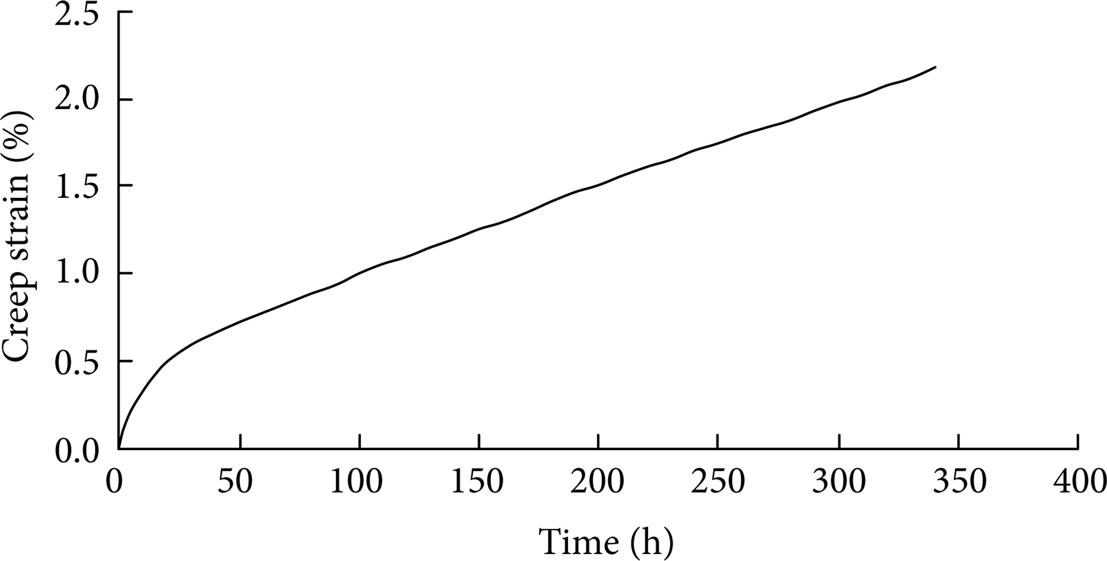
Triaxial creep test curve of salt rock.
3. Numerical Simulation of the Long-Term Stability of Salt Carven Gas Storage
3.1. Numerical Simulation Model
The simulated underground gas storage is shown in Figure 2. The buried depth is 1100 m to 1300 m and the upper rocks are simplified to equivalent stress. Based on the finite element software Abaqus, this three-dimensional model selects the range of underground from 500 m to 1500 m. The mudstone layer is set from under the surface of from 500 m to 1000 m and from 1300 m to 1500 m, and the salt rock layer thick is about 300 m, and also the top and bottom of the cavity are considered to be thick salt rock protection layer, 100 m and 50 m, respectively. Because of the symmetry of the structure, a quarter of the structure was taken as the research object to simplify the calculation. The mesh was divided by hexahedral grid and partial encryption. The height of the gas storage is 150 m and the biggest radius is 50 m, and the overall shape of the gas storage is like an ellipse. The affect region is 6 times as the biggest hole radius. To restrict three-direction deformation at the bottom of the structure by hinges, restrict normal deformation of the surrounding, and set the top free. Ignoring the influence of the interlayer in salt rock, specific of the three-dimensional grid diagram is shown in Figure 3.

Plan figure of gas storage.

Figure of three-dimensional mesh.
3.2. Parameter Selection
The long-term stability of gas storage was analyzed in 3D model based on finite element software Abaqus. The model of salt rock and mudstone adopts Drucker Prager, which can simulate the creep function to describe the material of the long-time elastic deformation. “Norton index models,” edited by Fortran language, were used to express the steady state creep of salt rock and mudstone which were shown as formula (1) and connect the main program of Abaqus with the subroutine. Mechanical parameters of salt rock were obtained by Chen et al. [9] in the indoor salt rock experiment as shown in Table 1, and the time unit is hour. Salt rock and mudstone creep parameters are as follows.
Salt rock: A = 1.018 × 10⁻⁸,n = 3.
Mudstone: A = 1.018 × 10⁻⁸, n = 2.
Rock material parameters.

Initial geostress balance: since there is no actual log data, geostress selected gravity stress.
Gas pressure, respectively, imposing 0 MPa, 4 MPa, 6 MPa, 8 MPa, 10 MPa, 12 MPa constant pressures, and annual circulation pressure on the gas storage, the circulation pressure was implemented by the “Amplitude” in Abaqus CAE. Taking supply and demand (changed by seasons) into account to decide the magnitude of annual circulation pressure, the specific is shown in Figure 4.
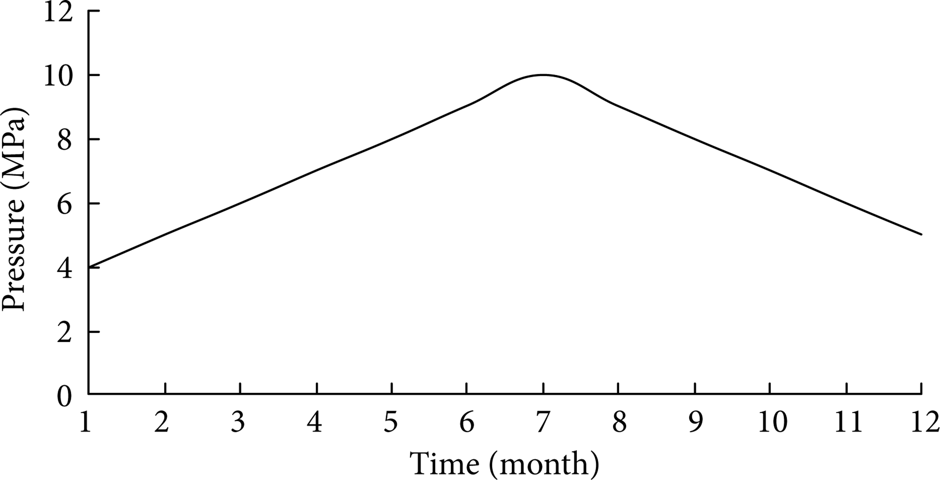
Cyclic internal pressure diagram.
4. Results and Analysis
4.1. Simulation Results under the Condition of Constant Pressure
Based on the software Abaqus, the author can obtain the displacement nephrograms and displacement vector plane under the constant pressures: 0 MPa, 4 MPa, 6 MPa, 8 MPa, 10 MPa, and 12 MPa, respectively, during 10-year creep. These Figures were shown as Figures 5, 6, 7, 8, 9, 10, 11, 12, 13, 14, 15, and 16.

Displacement nephogram when pressure is 0 MPa.
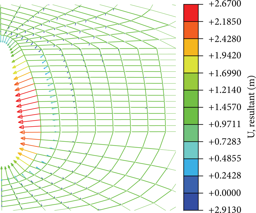
Displacement vector figure when pressure is 0 MPa.

Displacement nephogram when pressure is 4 MPa.

Displacement vector figure when pressure is 4 MPa.

Displacement nephogram when pressure is 6 MPa.

Displacement vector figure when pressure is 6 MPa.

Displacement nephogram when pressure is 8 MPa.

Displacement vector figure when pressure is 8 MPa.
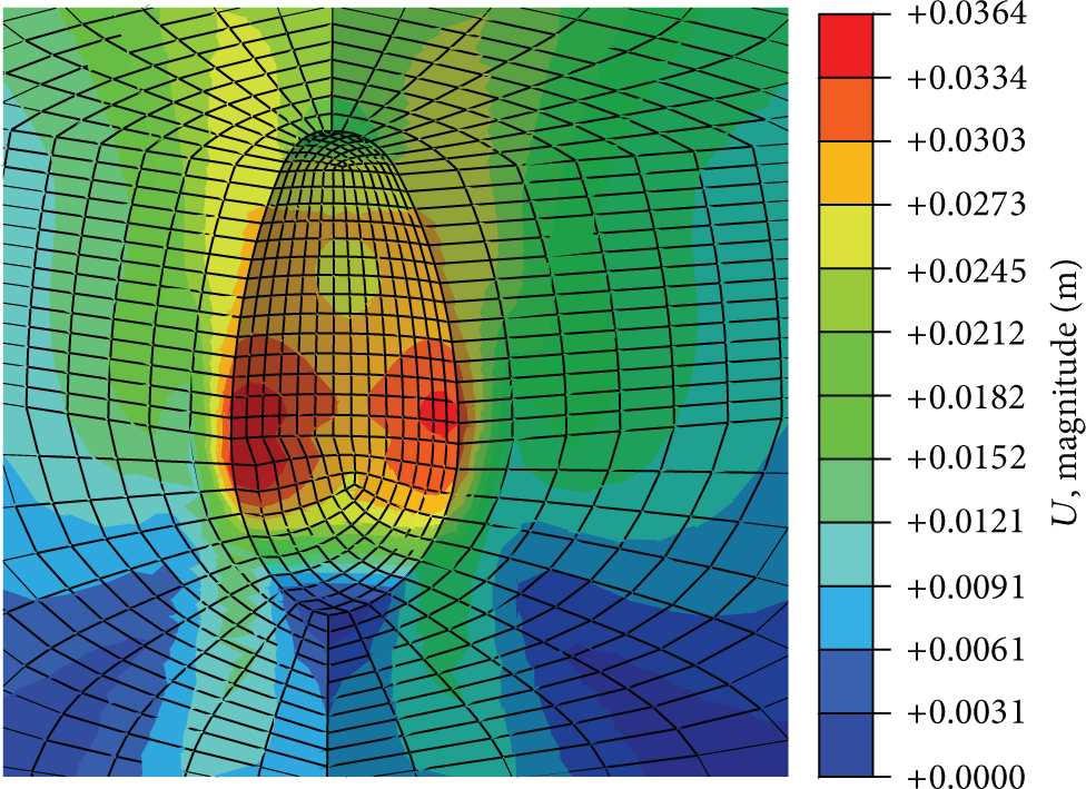
Displacement nephogram when pressure is 10 MPa.

Displacement vector figure when pressure is 10 MPa.
Displacement nephogram when pressure is 12 MPa.

Displacement vector figure when pressure is 12 MPa.
The numerical simulation results show that the inner wall of the gas storages shows a trend of internal contraction (12 MPa except) under the effect of different internal pressure creep for 10 years. The maximal displacement occurs in the central of the gas storage, and the most obvious creep that occurs in the condition of inner press is 0 MPa in which the maximal displacement is 2.913 m; the maximum displacement of 4 MPa, 6 MPa, 8 MPa, and 10 MPa is 0.618 m, 0.249 m, 0.105 m, and 0.035 m, respectively. Compared with the result under 0 MPa, the displacement of 10 MPa is nearly 100 times as that of 0 MPa. This suggests that the increase of pressure has obvious effect on inhibiting the cavity volume decrease. Therefore, during the gas storage operation, the condition of low pressure should be avoided as far as possible.
From the displacement vector Figures it can be found that when the gas pressure is less than 10 MPa, cavity is characterized by inward contraction, and under the condition of 12 MPa pressure, part of cavity mostly did not show the trend of inward contraction. On the contrary, in middle and bottom of the cavity, the deformations got a trend of expansion. From the figure of balanced geostress (shown in Figure 17) it can be seen that the geostress of the cavity is about 15 MPa, and because of the arch effect, the stress in bottom and top of the gas storage is very low, and then the rock showed a kind of outside enlarged trend under the effect of excessive internal pressure. If the value of internal pressure is too big, sealing problem will become more prominent because salt rock cavity has caused external expansion, even resulting in the tensile failure of rock mass. Therefore, during the running of gas storage, too high gas pressure should be a problem that should be avoided.

Stress nephogram after geostress balance.
In order to determine the optimal operation pressure of the gas storage, point A, in central of the cavity, was selected as the research object in Figure 18. The time-displacement curve of point A is shown in Figure 19.
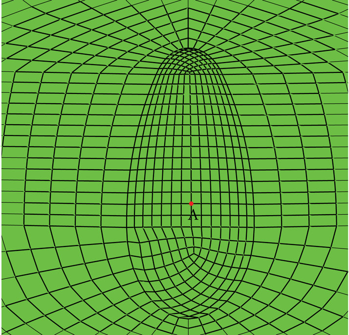
Sketch of reference point A.

Time-displacement curves of point A.
From the time-displacement comparison figure we can find that the displacement of point A decreases with the increase of operation pressure and changes from 2.75 m (0 MPa) to 0.029 m (10 MPa). The amplitude of displacement reduced under 4 MPa is especially striking, when the pressure exceeds 4 MPa, the displacement changes along with the change of pressure are no longer so obvious, and the displacement curves between 8 MPa and 10 MPa are basically closed. Therefore, we can conclude that the gas storage's optimum operation pressure in this operating mode is from 4 MPa to 10 MPa.
4.2. Cyclic Pressure
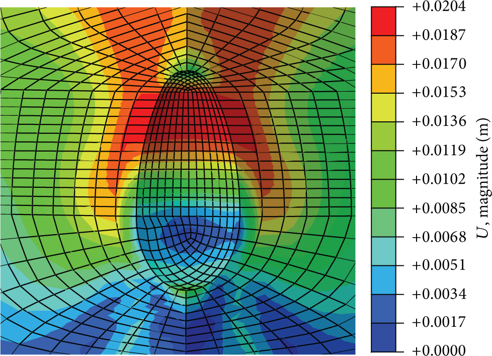
Under the condition of circulation working pressure after 10 years creep, the displacement nephogram and vector Figure of the cavity were shown in Figures 20 and 21. Outputting time-displacement curve of point A, this is shown in Figure 22.

Displacement nephogram and displacement vector plane figure of cyclic pressure.

Displacement nephogram and displacement vector plane figure of cyclic pressure.

Time-displacement curve of point A.
Simulation results show that, under the condition of the circulation working pressure given in Figure 4, after 10-year creep, the maximal displacement of underground gas storage is 0.32 m, less than the minimum pressure (0.618 m of 4 MPa) and higher than the maximum pressure (0.035 m of 10 MPa); this is a further indication of gas storage creep rate and decreasing with the increase of pressure. From time-displacement curve of point A, it was found that the displacement of point A changes with the change of pressure, and the overall trend is grown in fluctuating. In order to confirm the relationship between gas pressure and displacement, taking a whole year's time-displacement curve of point A as a separate argument, this is shown in Figure 23. From the figure, we can see that, compared with the “Convex” type of circulating pressure (Figure 4), the whole years’ time-displacement curve of point A is roughly “concave” type, opposed with the type of circulating pressure; therefore, the creep rate of gas storage is inversely with the gas pressure.
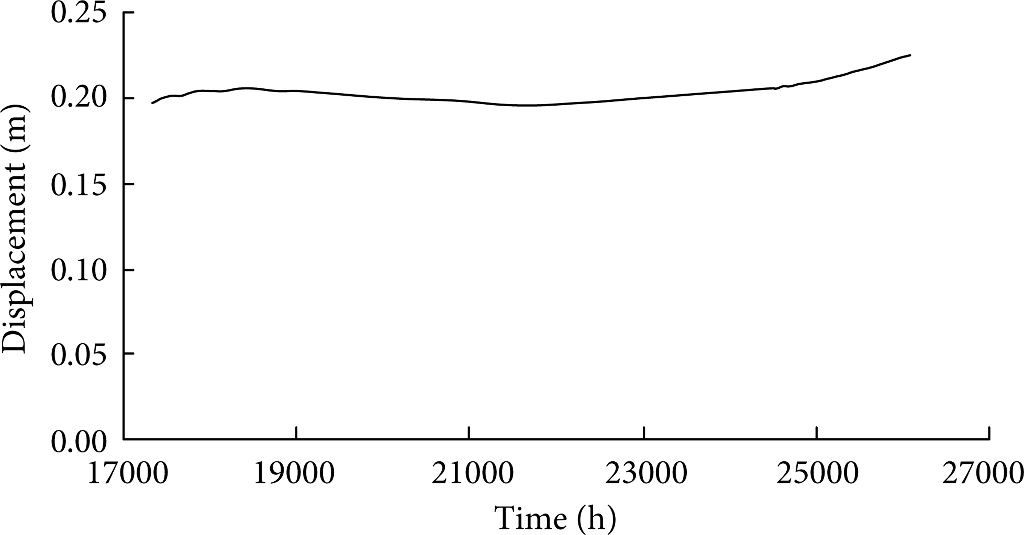
Time-displacement curve of point A during one year.
5. Conclusions
This paper establishes 3D model of underground salt cavern gas storage with the software Abaqus and successfully simulated the deformation of the gas storage by Drucker-Prager model and Nortron creep rules during 10-year running.
The long-term creep performance of underground salt cave gas storage is affected by internal pressure, the smaller the internal pressure creep is, the more obvious the creep and the greater deformation of gas storage are. The greater the internal pressure is, the smaller deformation of the gas storage is. Low pressure will cause the large deformation and lead to instability of gas storage; meanwhile, excessive high pressure of the gas storage may cause sealing problem. So both the low pressure and excessive high pressure must be avoided during the operation of gas storage.
We concluded that the gas storage's best operation pressure is 4 MPa to 10 MPa in this model and analyzed the gas storage's deformation when the inner pressure is cyclic variation after 10-year creep.
Conflict of Interests
The authors declare that there is no conflict of interests regarding the publication of this paper.
Footnotes
Acknowledgments
This work was financially supported by the Open Fund of State Key Laboratory of Oil and Gas Reservoir Geology and Exploitation (PLN1202) and the Natural Science Foundation of China (51174170).