
Abstract
It is important to evaluate the economic efficiency of boiler circulating pumps in manufacturing process from the manufacturers' point of view. The possibility of optimizing the pump casing with respect to structural pressure integrity and hydraulic performance was discussed. CFD analyses of pump models with different pump casing sizes were firstly carried out for the hydraulic performance evaluation. The effects of the working temperature and the sealing ring on the hydraulic efficiency were discussed. A model with casing diameter of 0.875D40 was selected for further analyses. FEM analyses were then carried out on different combinations of casing sizes, casing wall thickness, and materials, to evaluate its safety related to pressure integrity, with respect to both static and fatigue strength analyses. Two models with forging and cast materials were selected as final results.
1. Introduction
Boiler circulating pumps are used to circulate water within the boilers to enhance their operations, for example, in forced circulation boilers of subcritical drum type units [1] and start-up systems of ultrasupercritical and supercritical boilers [2]. They are designed for pumping water at relatively high temperatures (usually >300°C) and high pressures (usually >30 MPa), depending on the size and rating of the boilers.
Considering the extreme working environment, the overriding requirement for the design and manufacture of boiler circulating pumps is to ensure their safe operation, that is, to avoid structural failure of the pumps. On the other hand, it is also important to evaluate the economic efficiency in manufacturing process from the manufacturers’ point of view. At present, most of the parts of the pumps, including pump casing [3], are usually made of forged iron. In order to decrease the costs of production, pump manufacturers are actively seeking the possibility of reducing the costs of materials, for example, replacing the materials of the pump parts from forged to cast materials and reducing their volumes, and so forth.
This paper focuses on an optimization process of a centrifugal boiler circulating pump's casing, in sense of reducing the costs of production, while maintaining the structural pressure integrity and hydraulic performance. Pump casings with different internal sizes were numerically evaluated against the hydraulic performance of the whole pump by using computational fluid dynamics (CFD) analyses. Analyses of finite element method (FEM) were then carried out on different combinations of casing sizes, casing wall thickness, and materials, to evaluate its safety related to pressure integrity. This procedure yielded a satisfactory final design with respect to hydrodynamics and structures.
2. Case Studied
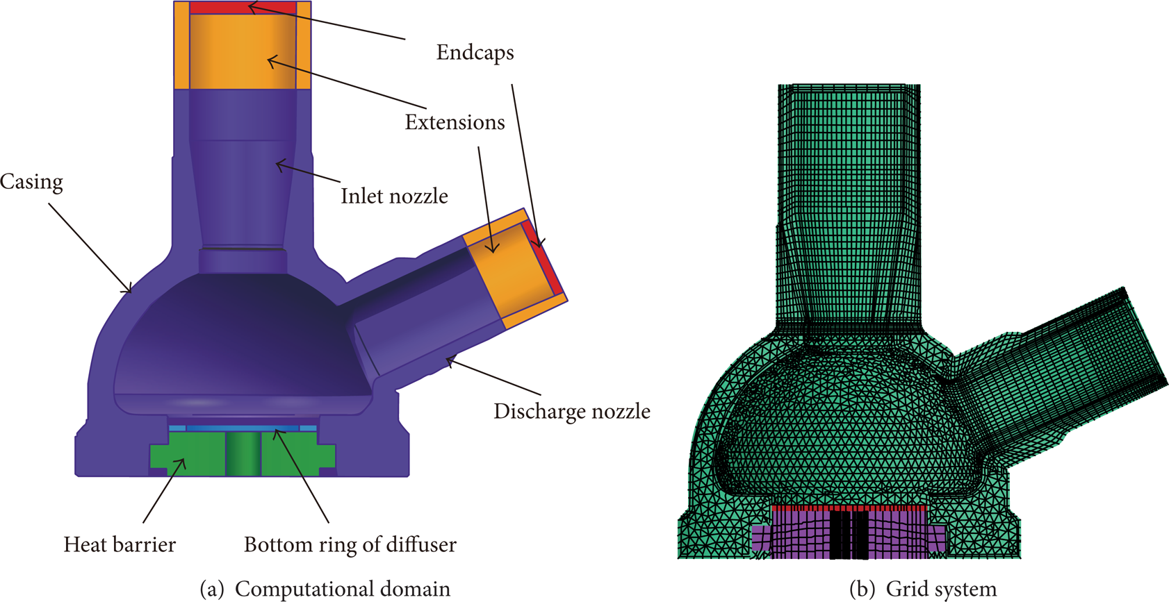
The pump studied is shown in Figure 1. Comparing with usual centrifugal pumps, several differences can be recognized. The pump casing is designed with a semispherical form and is axially insulated against the rotor motor with a heat barrier considering the extreme thermal and mechanical loading. A vaned diffuser is employed to recover the pressure energy and to reduce the radial forces at low flow rates. The discharge nozzle is oriented outward radially, at an angle to the axis of rotation of the pump impeller. The pump has the following specific speed value at design working condition:

where n is the rotational speed, Q is the flow rate, and H is the head. The number of impeller blades Z = 7, and the number of guide vanes Z G = 10.
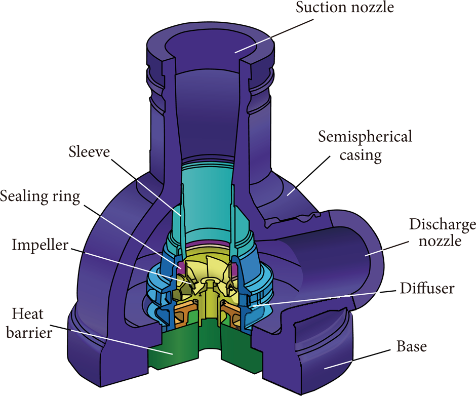
Boiler circulating pump.
3. Hydraulic Analyses
The hydraulic analyses of the pump include the validation of the CFD methods, predictions of pump hydraulic performance, and evaluations of different pump casing sizes.
3.1. Validation of the CFD Methods
The existing base model was firstly tested. Numerically calculated pump hydraulic performances were validated by comparisons with experimental results at normal-temperature normal-pressure (NTNP, 20°C, 0.33 MPa) conditions. Hydraulic performance predictions at high-temperature high-pressure (HTHP, 380°C, 32 MPa) conditions were then carried out. Apart from hydraulic performance predictions through steady flow studies, pressure fluctuations analyses were also performed with unsteady flow calculations. Since the temperature was kept constant in the HTHP cases, energy equation was not included in the calculations. RANS (Reynolds Averaged Navier Stokes) equations were solved with SST k-ω turbulence model at NTNP and RNG k-ε turbulence model at HTHP conditions, respectively, to ensure the compatibility of turbulence models and the grid systems.
The computational domain is shown in Figure 2. In order to simulate the fully developed fluid flows, extensions with length of about 5 times the diameter of the nozzles were added to the suction and discharge nozzles. Mass flow inlet conditions and pressure outlet conditions were applied at the end of these nozzles.
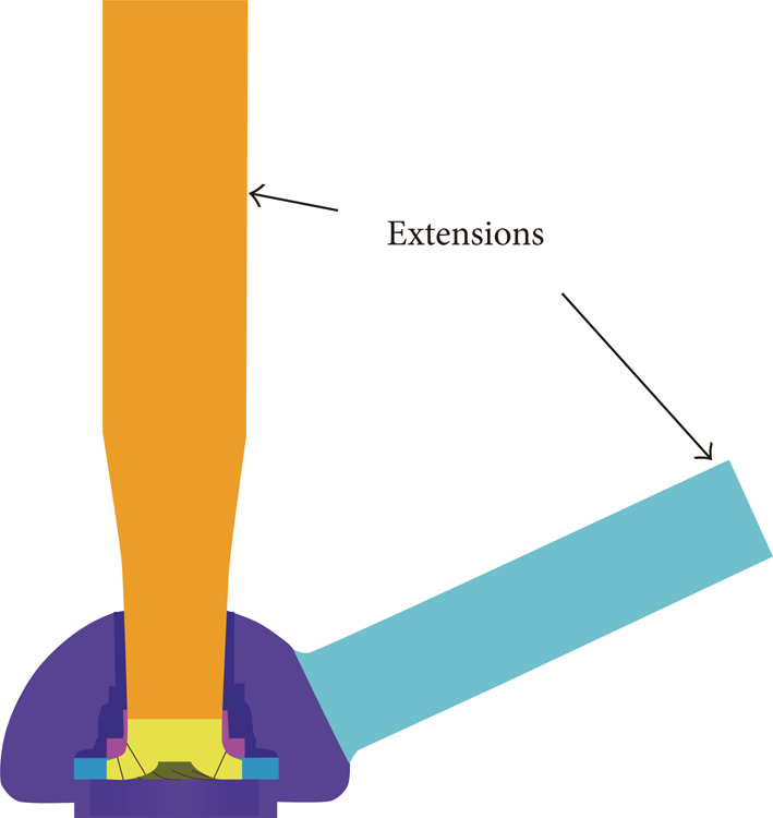
CFD computational domain.
The model's mesh system was developed in commercial software package ICEM. It was comprised of multiblock unstructured hexahedral grids in the whole computational domain. Local refinements to the boundary layer in the impeller and diffuser were applied (grids in impeller are shown in Figure 3). The height of the first-layer grids is 0.05 mm. The values of y+ are compatible with the chosen turbulence models used for NTNP (y+ <30) and HTHP (30<y+ <200) calculating conditions, respectively. Verification of grid independence was performed with respect to the nondimensional pump hydraulic efficiency
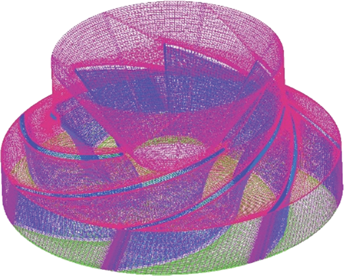
Grids in impeller.
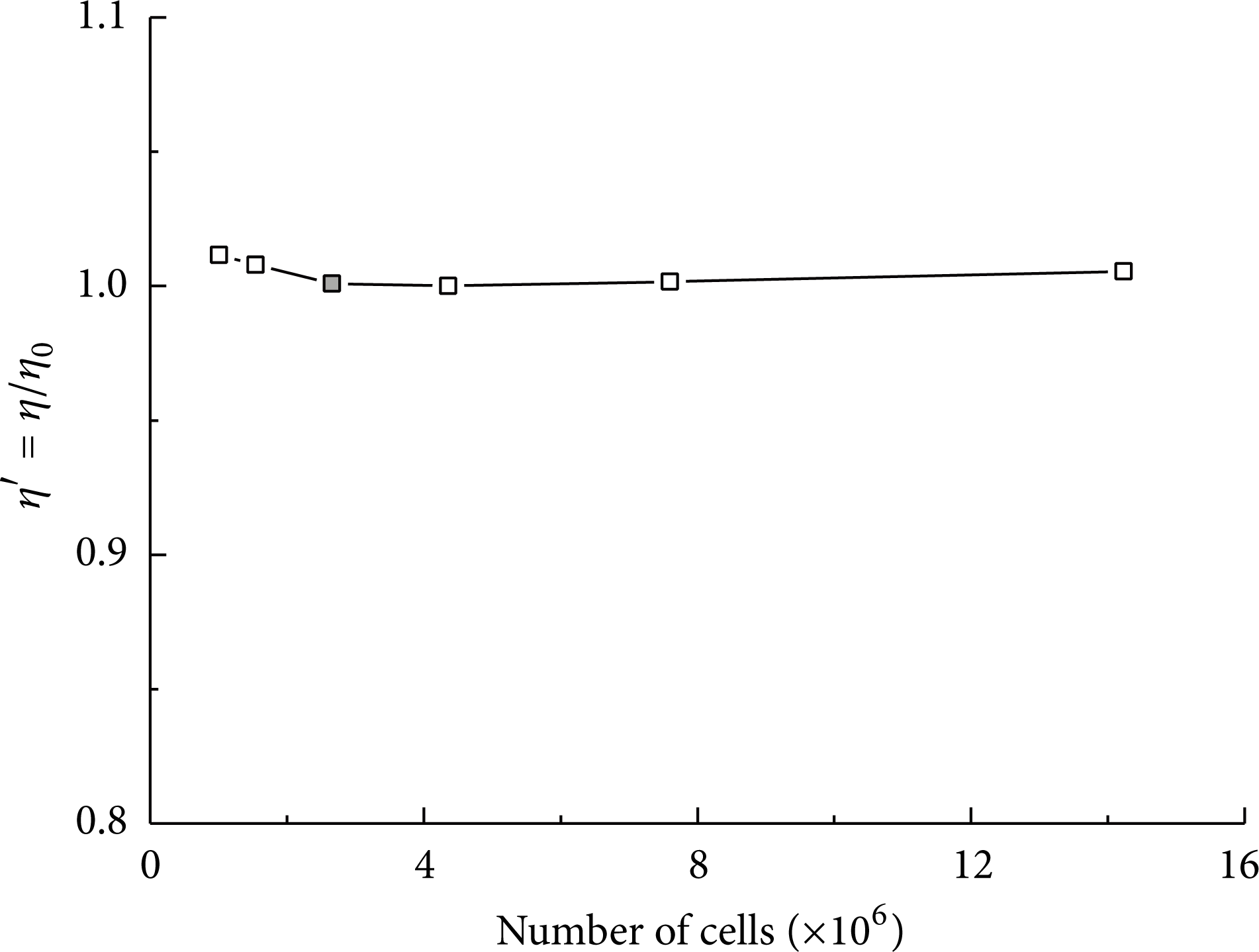
Verification of grid independence at NTNP.
For unsteady calculations, time independence tests were performed to choose the proper time step size. As shown in Figure 5, FFT analyses on the pressure fluctuations at monitoring point A at NTNP were carried out against three different time step sizes (corresponding to 0.5°, 1°, and 2° of pump impeller rotations, resp.) for calculations. The amplitudes p A and frequencies f of the pressure fluctuations were normalized against the rated head H0 and the rotational frequency fn, respectively. Characteristics of pressure fluctuations with BPF (blade passing frequency) and 3BPF were consistent in all the calculations, and only mild differences were observed in the low frequency area (<fn). Considering the computational accuracy and calculation loads, time step when pump impeller rotates 1° was chosen for unsteady flow calculations.
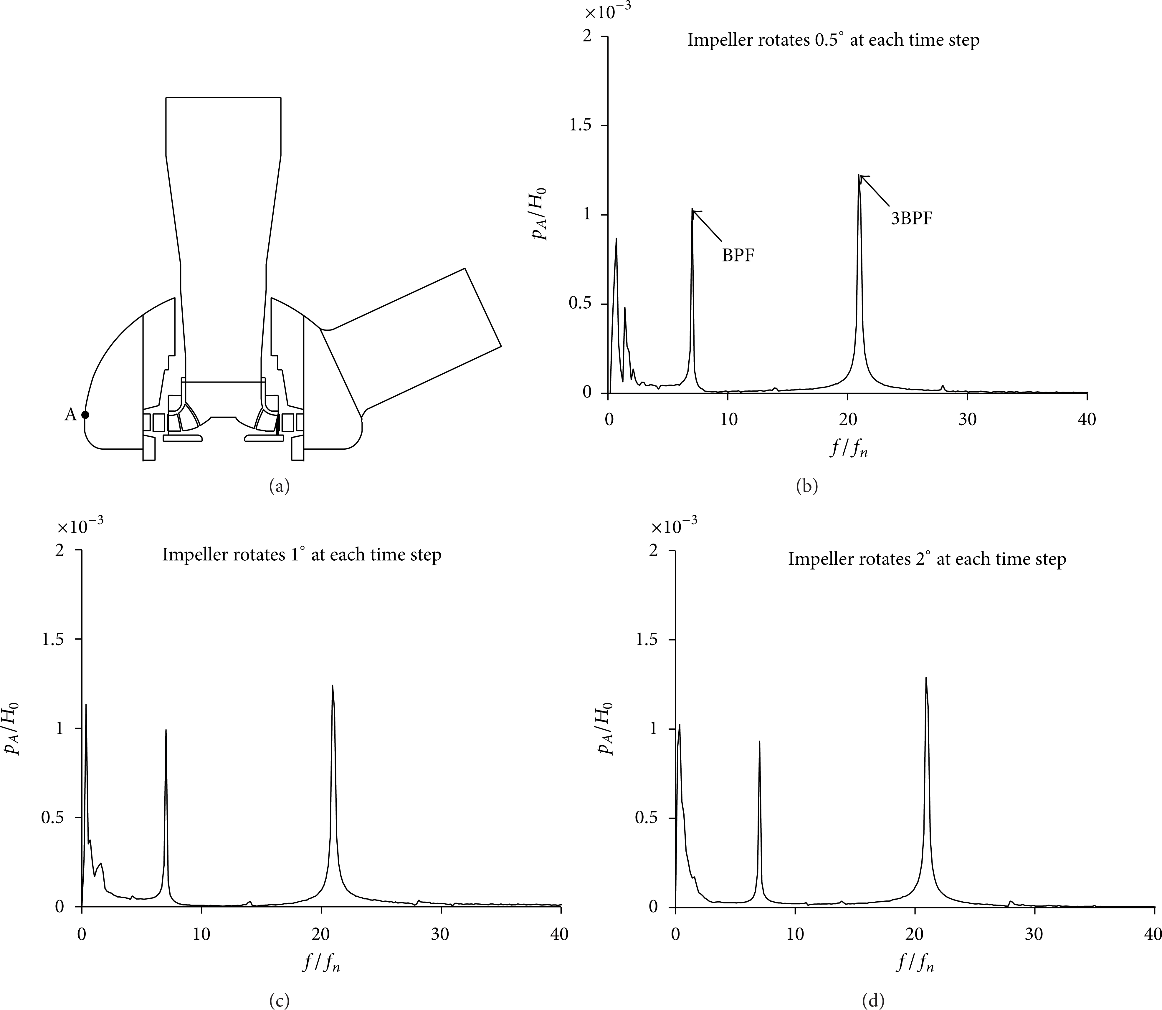
Verification of time independence, (a) monitoring point for analyzing pressure fluctuations; (b), (c), and (d) FFT results of pressure fluctuations at tested time step sizes.
3.2. Hydraulic Performances
Since the testing of the unit at its working temperature and pressure (HTHP) is impractical and too costly to be justified, experiments were performed at NTNP conditions. As shown in Figure 6, the CFD calculations successfully predicted the hydraulic efficiency at design operating point at NTNP. Only minute discrepancies can be observed between CFD and experiments in the flow rate range: Q = 0.6Q0∼1.4Q0, where Q is the flow rate and Q0 is the design flow rate.

Hydraulic efficiencies at NTNP.
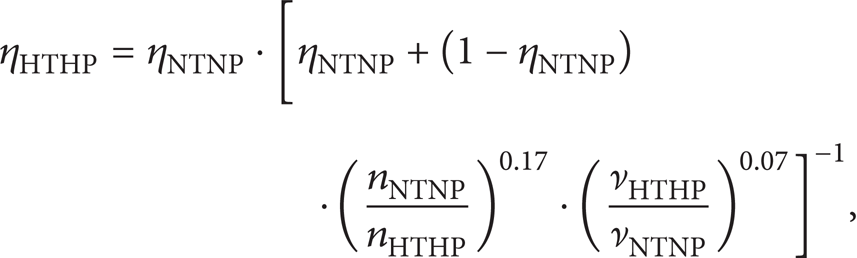
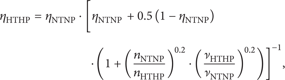
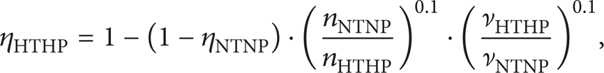
Predictions were then made to the hydraulic efficiencies at HTHP, by substituting the physical properties (density ρ and kinematic viscosity ν) of water at NTNP with values at HTHP in the calculations. In engineering industry, several correction formulae have been employed to estimate the effect of changes in temperature on efficiency. By assuming the forms of losses with respect to the variations of Reynolds number, the following formulae have been proposed:
correction formula by Karassik [4]:
Misarik who proposed the following formula [5]:
correction formula by DIN standards [6]:
correction formula employed by Sulzer Company [6]

Figure 7 shows the comparisons between the CFD predictions at HTHP and the estimates based on the experimental results at NTNP by the listed correction formulae. CFD and correction formulae give close predictions at Q = Q0 at HTHP. Moderate deviations exist at working conditions with partial and overflow rates. Since it is more difficult to ensure the quality of grids at HTHP due to the changes of physical properties of water, it is acceptable to use the previous correction formulae for performance estimates based on CFD studies at NTNP in engineering practice.

Hydraulic efficiencies at HTHP.
3.3. Influence of Sealing Ring
The CFD analyses and experimental tests so far were carried out with the model pump with smooth sealing ring, while the prototype pumps are equipped with honeycomb-like sealing rings (Figure 8). In order to predict the hydraulic performance of the prototype pump, the influence of different sealing rings was evaluated. SST k-ω turbulence model was used for steady flow calculations. Due to the heavy computational load and difficulties in experiments including the sealing rings in the pump ensemble, evaluations were performed with the individual sealing rings.

Honeycomb-like sealing ring.
The whole sealing ring was comprised of 14 × 285 = 3990 basic elements. As a simplification, a subdomain of 14 × 5 = 70 elements (
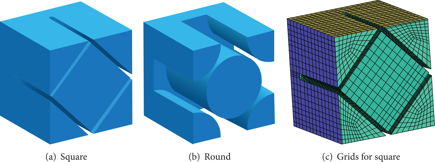
Hydraulic element and grids for honeycomb-like sealing rings.

Hydraulic performance of sealing rings.
3.4. Optimization of Casing Diameter
Now that the CFD methods have been validated and the hydraulic performances of the pump have been successfully predicted, the optimization of the pump casing diameter was numerically carried out, in terms of the pump hydraulic efficiency and the material costs of pump casing. The calculations were performed with SST k-ω turbulence model at NTNP conditions.
As shown in Figure 11, the model pump studied has a semispherical-shaped casing, with original inner diameter D40.

Inner diameter of pump casing.
Firstly, an estimate of the optimum cross-sectional area of the pump casing was performed, by applying the velocity-coefficient method [7]. The method was validated with conventional circular casing (Figure 12), and it was used here to provide a reference value for our semispherical casing.

Hydraulic passage of pump casing.
The average velocity across the cross-sectional area of the pump casing can be evaluated as

where H0 is the design pump head at NTNP and k3 is the velocity-coefficient according to the specific speed of the pump. The cross-sectional area of the casing can then be estimated by

An asymptotic approach was then used to derive a reference diameter of pump casing. The fact that the result by the described velocity-coefficient method was 0.710D40 indicates the possibility of reducing the inner diameter of the pump casing.
Three values for the inner diameter of the pump casing were selected for evaluation, namely, 0.750D40, 0.875D40, and 1.125D40. As shown in Figure 13, hydraulic efficiency and head of the pump with 0.750D40 showed a distinct decrease, compared with D40. The cases with 0.875D40 and 1.125D40 showed no apparent differences with D40.

Comparison of pump hydraulic performances with different casing inner diameters.
An analysis of energy balance was performed, where the energy variance ΔE in the hydraulic parts for all the cases was normalized by the head with D40 at NTNP (Figure 14). It is shown that, for the case of 0.750D40, an increase in energy variance occurred in casing and discharge nozzle, causing a deterioration in the hydraulic performance of the pump. Figure 15 shows the streamlines in the pump casing and discharge nozzle. Comparing with other cases, flow separation existed at the inlet of the discharge nozzle with the case of 0.750D40.
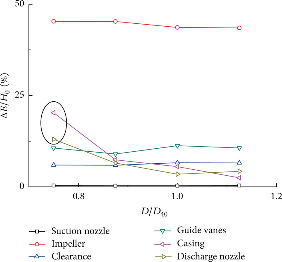
Energy balance in pump at Q = Q0.

Streamlines in casing and discharge nozzle.
As a result, the case with 0.875D40 was selected for further analyses. The hydraulic efficiency was similar, and the volume of the pump casing decreased about 10% comparing with the original pump casing, if the thickness of the casing was unchanged.
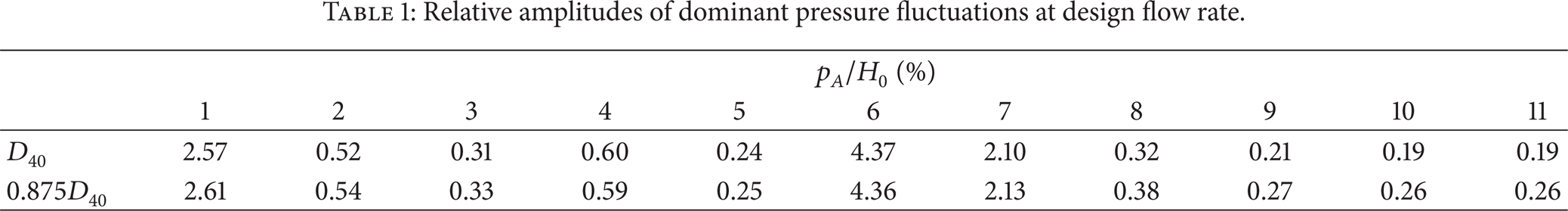
In order to evaluate the influence of the pump casing modification on the pressure fluctuations in the pump, monitoring points were positioned as illustrated in Figure 16. No apparent changes in the amplitudes of dominant pressure fluctuations were observed, as shown in Table 1. It was also observed that the amplitudes were about 0.03% of the working pressure of the pump. Thus it is reasonable to ignore the influence of hydraulic pressure fluctuations in the structural analyses.
Relative amplitudes of dominant pressure fluctuations at design flow rate.

Monitoring points for pressure fluctuations.
4. Structural Analyses
The influence of the material and thickness of pump casing was discussed, in terms of pressure integrity. Both static strength and fatigue strength were tested.
4.1. FEM Model
The computational domain for structural analyses includes the solid structures of the pump casing assembly (Figure 17(a)), instead of flow passage in the previous CFD analyses. Extensions and endcaps were added to the model, in order to apply the correct nozzle loads, considering the actual pipelines connections. The lengths of the extensions L a and the thickness of the endcaps T e were calculated by the following formulae, respectively:

where D o and D i are the outer and inner diameters of the corresponding pipe.
FEM model.
Grid system for FEM analyses was developed in ANSYS Workbench comprising tetrahedral grids in the semispherical casing, pentahedral grids on the boundary of the casing, and hexahedral grids in other parts (Figure 17(b)). Due to its axial symmetry, only half of the model was analyzed, with total about 100,000 grid cells.
4.2. FEM Analyses
The analyses were performed in ANSYS Mechanical APDL software package. In this study, the material of the pump casing was set as a forging material SA182 Grade F1 or a cast material SA216 Grade WCB. The material for the heat barrier was set as SA182 Grade F1.
10 paths were selected for evaluation of the equivalent stress at defined loading conditions, including 3 primary paths (no. 1∼3) located on the continuous geometry and 7 local paths (no. 4∼10) located on the transition regions of the geometry, as shown in Figure 18.

Paths for FEM analyses.
According to ASME code, the equivalent stresses were compared to an allowable value of equivalent stress, where the pump casing was treated as a pressure vessel [8]. The value of the equivalent stresses was calculated using the maximum distortion energy criterion; that is, the equivalent stress is equal to the von Mises equivalent stress. General primary membrane equivalent stress P m , local primary membrane equivalent stress P L , and primary bending equivalent stress P b plus secondary equivalent stress Q were tested against allowable stress S m for design condition and yield strength S y for hydrostatic test condition.
(1) Design Condition. For primary paths, the following requirements must be satisfied:

For local paths, the following requirements must be satisfied:

(2) Hydrostatic Test Condition. Only primary paths shall be tested.
A calculated P m shall not exceed the applicable limit given below:

A calculated P m + P b shall not exceed the applicable limits given below:

A static strength usage factor U s , defined as the ratio between the left hand side and right hand side of these equations, was used to evaluate the safety of the casing under static strengths. Safe operation of the unit requires U s <1, and smaller U s value gives higher safety allowance. The influence of the hydraulic pressure fluctuations was ignored; thus the static pressures of both design and hydrostatic test conditions were applied for calculations. Six models with different inner diameter, wall thickness (T0 is the wall thickness of the original casing model), and material of pump casing were studied, and the results are shown in Table 2. It can be seen that, with the same wall thickness, the model with modified casing inner diameter has superior (0.875D40) behavior. The fact that the models with cast material also satisfy the static strength requirements indicates the possibility of changing the pump casing material.
Static strength analyses.

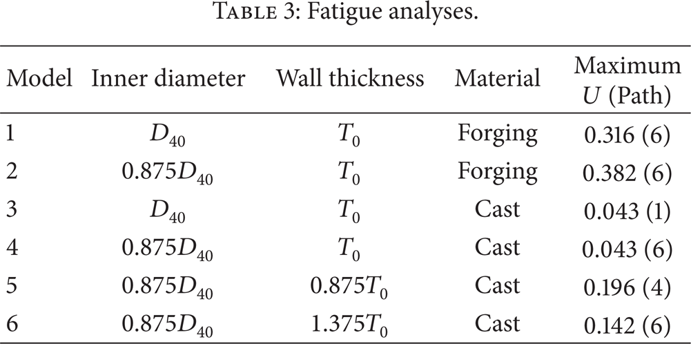
The fatigue strength of the pump casing was evaluated in consideration of three quasistationary stress cycles, that is, hot start-up and shutdown (cycle 1), cold start-up and shutdown (cycle 2), and sudden step load changes (cycle 3). The numbers of occurrences of the three cycles during a life time of 30 years are n1 = 4500 for cycle 1, n2 = 120 for cycle 2, and n3 = 3000 for cycle 3, respectively. Tresca's maximum shear stress criterion was applied to evaluate the strength. The applicable design fatigue curve was used to determine the maximum allowable number of each repetition, N1, N2, and N3. The usage factors of each stress cycle were calculated by
Fatigue analyses.
5. Conclusions
In order to optimize a centrifugal boiler circulating pump's casing to reduce the costs of production without jeopardizing its structural pressure integrity and hydraulic performance, CFD analyses of pump models with different pump casing sizes were firstly carried out for the hydraulic performance evaluation. The effect of the variations of working temperature on the performance was discussed, and the sealing ring was modeled by a drop in efficiency through evaluations of leakage flow rates. It was concluded that the casing with diameter of 0.875D40 has a considerable volume decrease and small drop in hydraulic performance and thus was selected for further analyses. FEM analyses were then carried out on different combinations of casing sizes, casing wall thickness, and materials, to evaluate its safety related to pressure integrity. Both static and fatigue strength analyses were performed on 10 paths. It can be seen that the forging model with inner diameter 0.875D40 and wall thickness T0 is one of the optimization results. If the casing can be cast, the model with inner diameter 0.875D40 and wall thickness 0.875T0 can also be considered.
The methods described in this paper provide an engineering available procedure for hydraulic and structural optimization of centrifugal boiler circulating pump's casing. Further studies can involve changes in terms of casing form and nonuniform wall thickness.
Conflict of Interests
The authors declare that there is no conflict of interests regarding the publication of this paper.