
Abstract
In an antenna for a UHF RFID reader of wireless sensor networks (WSN), receiver sensitivity in sensing multitags from remote distances is an important performance index. This study designed a dual structured Z-slot antenna with optimized receiver sensitivity to enhance the sensitivity to a circularly polarized antenna with an isotropic pattern for a UHF RFID. Through analysis of performance in the designed antenna, the following was verified: return loss
1. Introduction
RFID is an electronic tag and detection system that confirms information on things and detects surrounding conditions as one of the several tasks. A variety of radio frequencies and techniques are used in RFID systems [1, 2].
There have been a variety of studies in using the HF band (13.56 MHz), the UHF band (860 ~ 960 MHz), and the ISM band (2.4 GHz) as the standard RFID frequency bands for WSN [3]. As HF band RFID communication uses magnetic coupling, the receiver area of the antenna is very narrow and as the ISM band RFID is sensitive to the surrounding environment, the performance and sensitivity of the RFID system varies [1, 2]. However, the UHF band is the most outstanding for recognition rates and distance, and many tags can be recognized quickly using the radiation of electric waves. Also, as the signal is very stable in the surrounding environment and the tags and tag chips for this frequency can be produced at low prices, it is known that this is the most appropriate frequency for the realization of RFID technology and sensor networks [4, 5].
However, for a plane polarized antenna in the UHF band, errors may occur due to reflection and the interference of signals when multipath signals from the RFID tag are detected, and to recognize tags, the location of the tag has to be in line with the polarized plane [6, 7]. That is, for the plane polarized antenna, as electronic waves are radiated in a linearly polarized way, it is hard to recognize many tags simultaneously according to the locations of tags and the directionality of tag antennas and multipaths can be causes of disruptions [8]. To minimize errors due to multipath signals and gain high recognition rates regardless of the directions tag antennas face, a circularly polarized antenna is used. For a circularly polarized antenna, when two right-angled signals with different status and the same amplitude are polarized, electromagnetic waves are radiated circularly [9, 10]. This is more effective for recognizing several tags regardless of the locations of the tags and the directions of the antenna. That is, for a directional pattern antenna, gain is high but recognition ranges of tags are low [11]. For an isotropic pattern, antenna gain is low but the recognition range of tags is wide, so studies to enhance receiver sensitivity with isotropic antenna over a wide range have been carried out [12–15].
This study designed an isotropic antenna with high receiver sensitivity and an isotropic pattern for UHF RFID. To design and manufacture circularly polarized isotropic antennas, the signals of readers were divided into two signals of the same magnitude and an incidence difference of 90°. Electricity was supplied to a strip line with a length of
This study is composed of the following: Section 1 describes the design of circularly polarized antennas with an isotropic pattern for UHF RFID readers of WSN, Section 2 describes the design, manufacture, and simulation of the antennas for readers, Section 3 measures the parameters of the antennas manufactured and their performance, and Section 4 concludes the antennas designed.
2. Design and Simulation of an Antenna for Readers
We have designed and manufactured a circularly polarized antenna and Z-slot antenna with isotropic pattern.
The processes are as follows.
2.1. Design and Manufacture of the Proposed Antenna
The block diagram of circularly polarized antennas for UHF RFID readers of WSN with an isotropic pattern is presented in Figure 1. For compatibility with different RFID readers a microstrip line was designed as shown in Figure 2. The inductance value

Composition of antennas for the UHF RFID reader of WSN designed.

Design and manufacture of the PCB.
As seen in Figure 2, a hybrid coupler with insertion loss of 0.16 dB and a status difference of 90° was used to give a status difference of 90° from the original signal. To divide signals into two right-angled linear signals with the same amplitude, two strip lines with a length of
To achieve an isotropic pattern, the diagonal length of the radiation plate was

Design and manufacture of a Z-slot reflection plate.
2.2. Simulated Results for Radiation Pattern Characteristics
We used the ADS (advanced design system) 2004A of Agilent company for simulating the manufactured antenna. The simulation direction of the designed circular polarization antenna is as shown in Figure 4. The simulation result presented that it had high power density at 0360° direction to x-, y-, and z-axis (isotropic pattern) as shown in Figure 5.

Simulation of the direction of the designed antenna.

3D simulation results of the z-axis radiation pattern.
3. Parameter Measurement of the Designed Antenna and Performance Analysis
We measure and analyze the performance of the designed antenna as shown in the following.
3.1. Measurement of Return Loss
If there are unmatched impedance points in the transmission system, power reflection occurs there and part of the input power is reflected. Here, the ratio of the input power to reflected power is the return loss.
Measurement results for the return loss
Return loss (


Return loss
The wideband of the return loss of −10 dB was between 720.25 MHz and 1.12 GHz and the wideband of the axis rate of 3 dB was within 1.2 dB.
3.2. Measurement of the Impedance Matching Parameter
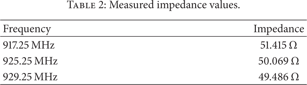
As a result of measuring the matching parameters of the designed antenna, matching was carried out with 50.069 Ω at 925.25 MHz as shown in Figure 7 and VSWR was from 1.001 to 1.028. It was discovered that this is compatible with different RFID readers of WSN. The impedance of the designed antenna is presented in Table 2.
Measured impedance values.

Measurement results of impedance parameters.
3.3. Test Environment and Radiation Pattern Measurements
3.3.1. Test Environment for Antenna Radiation Pattern
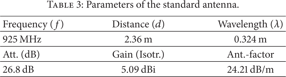
The designed antenna radiation pattern was measured by an absorber system. To measure performance, the circularly polarized Z-slot antenna was placed as a target, as seen in Figure 8, and a horn antenna was used as a standard for comparison. The two antennas had a separation distance of 2.36 m. For the standard, a BBHA-9120-D made by SCHWARZBECK was used and the parameters are as presented in Table 3.
Parameters of the standard antenna.

Test environment for the radiation pattern.
The equation defined by H. T. Friis which describes this wave behavior in “free space,” called the Friis Transmission Equation, is [16–18] as follows:

where
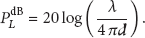
It is convenient to express Friis formula in terms of

where the path loss is defined as
3.3.2. Measurements of Antenna Radiation Pattern and the Gain Parameter
To measure the radiation pattern and antenna gain according to the directions of the designed antenna, the standard antenna and the designed antenna were rotated horizontally and vertically and the pattern and gain were measured in the four different aspects.
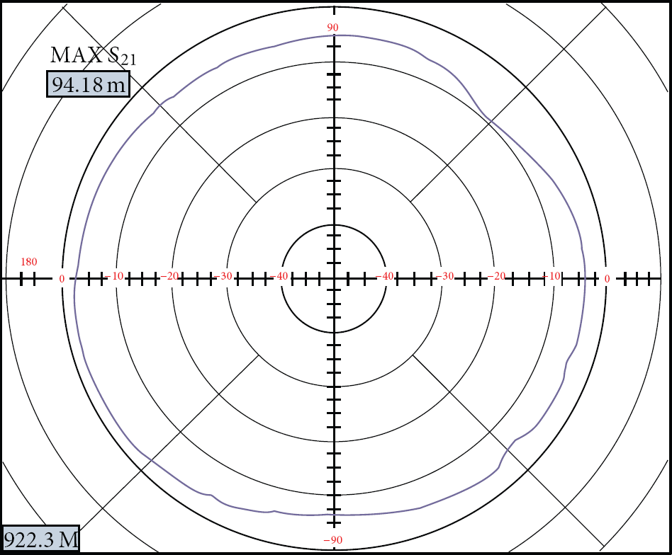
Figure 9 presents the results of the test where the standard antenna was set horizontally and the designed antenna was set in front. The antenna gain was 5.28 dBi and

Radiation pattern for the antenna gain 1 (the standard antenna: horizontal and the designed antenna: frontal).
Figure 10 presents the results of the test where the standard antenna was set vertically and the designed antenna was set in front. The antenna gain was 5.83 dBi and
Radiation pattern for the antenna gain 2 (the standard antenna: vertical and the designed antenna: frontal).
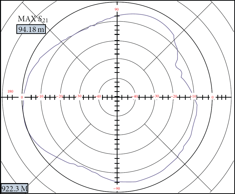
Figure 11 presents the results of the test where the standard antenna was set horizontally and the designed antenna was turned at 90°. The antenna gain was 7.36 dBi and

Radiation pattern for the antenna gain 3 (the standard antenna: horizontal and the designed antenna: turned 90°).
Figure 12 presents the results of the test where the standard antenna was set vertically and the designed antenna was turned to 90°. The antenna gain was 7.46 dBi and
Radiation pattern for the antenna gain 4 (the standard antenna: vertical and the designed antenna: turned 90°).
Table 4 presents the results of comparing the antenna gains measured and the deviations of the isotropic gains under the four different test environments. The gain of the antenna manufactured through a Z-slot formed on the radiation plate was about 7.36 dBi. The largest gain is a little low, but the deviation in isotropic gain was 1.3 dB, which indicates that the radiation pattern is superior.
Measured antenna gains and the deviations of the isotropic gains under the four different test environments.

3.3.3. Radiation Pattern Comparison according to the Z-Slot Plate Parameters
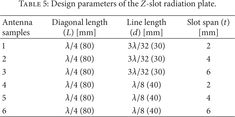
The design parameters of the Z-slot formed on the antenna radiation plate, that is, the diagonal length
Design parameters of the Z-slot radiation plate.

Antenna radiation plates according to the Z-slot parameters.
Figure 14 shows the results of the test where the standard antenna with an unsatisfactory radiation pattern was set vertically and the designed antenna was set in front to measure the radiated power according to the Z-slot parameters. Figure 15 shows the results of the test where the standard antenna was set vertically and the designed antenna was turned to 90°. As a result of measuring the radiated power according to the Z-slot parameters, the larger the slot span was, the bigger the radiation gain was. When the slot span was larger than 6 mm resonance point,

Radiation pattern data according to Z-slot parameters 1 (standard antenna: vertical and the designed antenna: frontal).
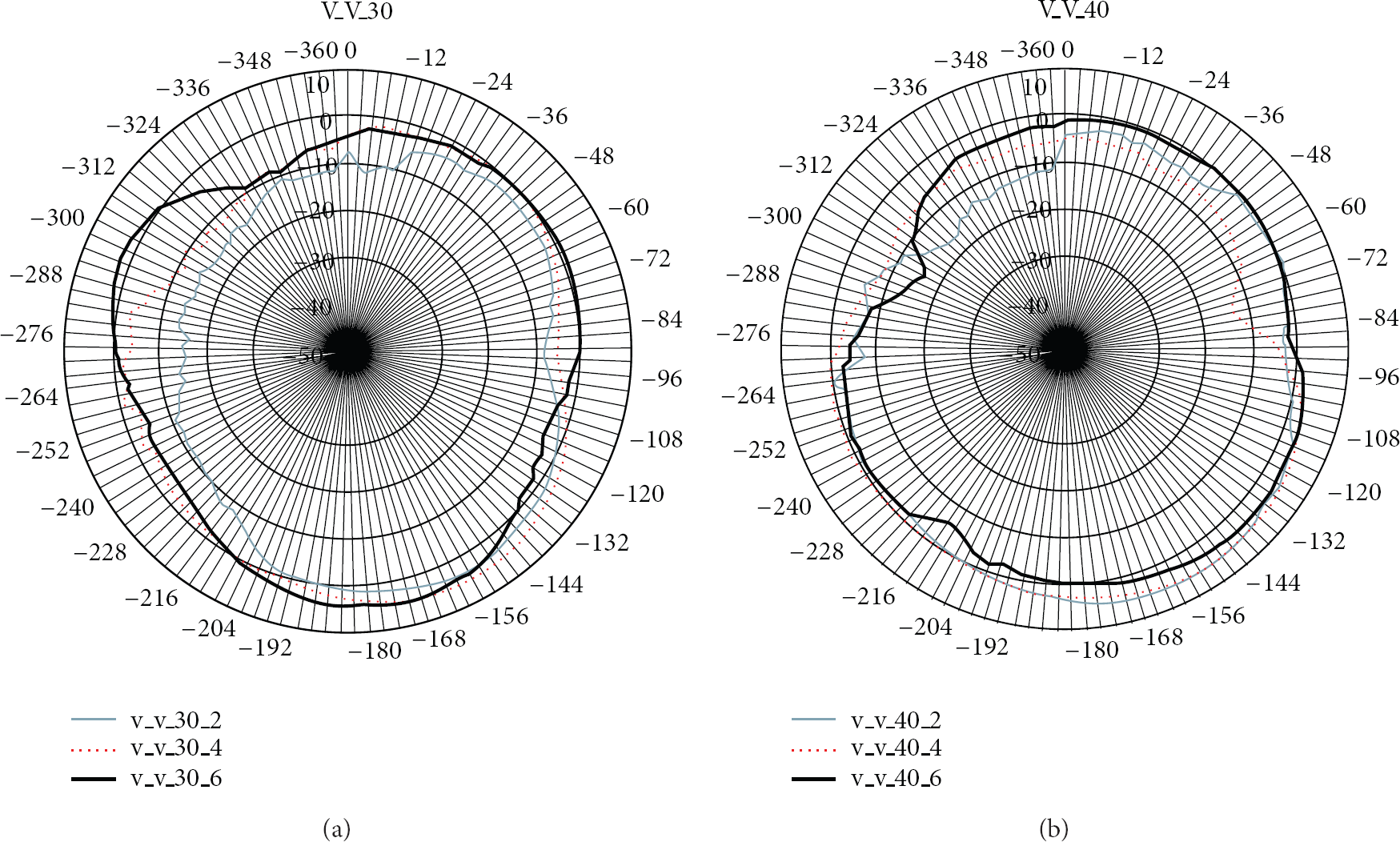
Radiation pattern data according to Z-slot parameters 2 (standard antenna: vertical and the designed antenna: turned 90°).
3.3.4. Analysis of the Radiation Pattern according to the Radiation Plate
To analyze radiation patterns according to the presence of the Z-slot on the radiation plate, the radiation pattern was measured with the standard antenna set vertically and the designed antenna turned 90°.
As a result, it was discovered that the maximum antenna gain without a Z-slot was about 9.09 dBi and

Radiation patterns with and without the Z-slot on the radiation plate (standard antenna: vertical and designed antenna: turned 90°).
3.3.5. Performance Comparison
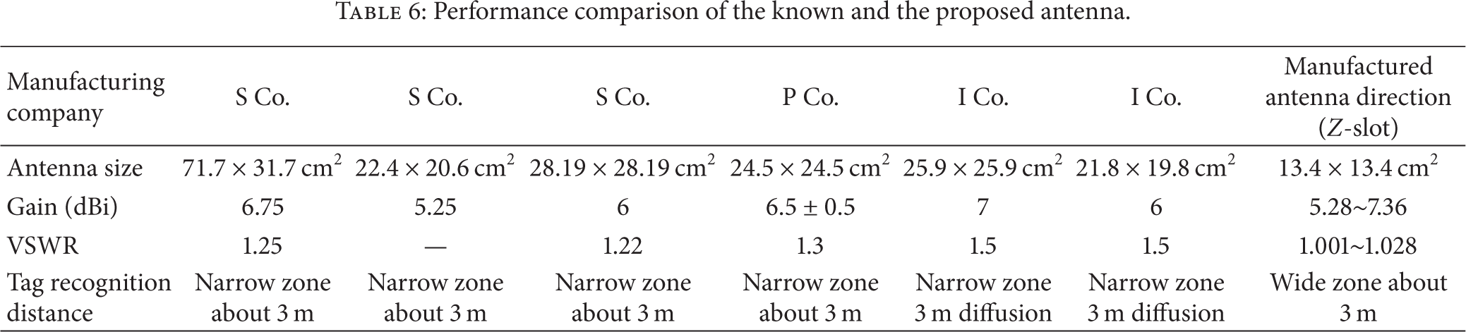
Table 6 shows the electric characteristics of the designed antenna with the RFID antenna. The known antenna was more than 21 cm2 in size while the designed antenna is only about 13.4 cm2. However, the antenna gain was the same as that of the known antenna, 5.28 ~ 7.36 dBi, although its size is smaller. The VSWR of the designed antenna was 1.028, higher than that of the known antenna. The tag recognition distance of the known antenna was about 3 m in a narrow range while that of the designed antenna was about 3 m in a wider range.
Performance comparison of the known and the proposed antenna.
4. Conclusion
This study designed a dual structured and circularly polarized Z-slot antenna for UHF RFID readers of WSN with an isotropic pattern.
To recognize many tags at a remote distance at the same time without errors, the designed antenna had an insertion loss of 0.16 dB and used a hybrid coupler with a status difference of 90° so there was a status difference of 90° from the original signal. Also, to separate signals into two right-angled linear signals of the same amplitude, there were two strip lines with a length of
The designed antenna was half the size of the known antenna, but it had an isotropic radiation pattern as good as and with the same electrical characteristics as the known one and recognized passive tags over a wide range. Such a dual structured and circularly polarized Z-slot antenna with an isotropic pattern can contribute to enhanced receiver sensitivity through maximizing antenna efficiency and to the development of antennas for UHF RFID readers of WSN with respect to compatibility with other systems.
Footnotes
Conflict of Interests
The authors declare that there is no conflict of interests regarding the publication of this paper.
Acknowledgment
This study was supported by research fund from Chosun University, 2012.