
Abstract
Optimization of a vector showerhead in a vertical reactor involves thousands of holes on the showerhead face plate and the spatial distribution of physical fields, so parameterizing the geometry configuration of the holes in high resolution is very difficult, which makes the conventional optimization methods hard to deal with. To solve this problem, a profile error feedback (PEF) optimization solution was proposed to optimize a vector showerhead gas delivery system for the control of mass transport. The gas velocity profile in the reactor and the continuous-feature impedance distribution profile on the showerhead face plate are defined as design objective and variables, respectively. A cyclic iterative approximation idea was implemented in this solution. The algorithm was started from a guessed initial design model and then cyclically adjusted the design variables by the constructed PEF iterative formula to generate a better model and to make the gas velocity profile in the critical domain of the new model continually approximate to the expected profile, until it could be accepted. Finally, the optimized impedance profile was mapped to the holes geometry configuration through the established equivalent impedance model for the showerhead face plate.
1. Introduction
Showerhead gas delivery system is widely used in the process reactor chamber of semiconductor equipment. The functions of different type showerhead systems in different reactor chambers are basically the same as those controlling mass transport in the chamber to obtain good process uniformity. With the increasing size and narrowing critical dimension of a wafer, semiconductor manufacturing has been asking for more stringent requirements on the process uniformity, and meanwhile the showerhead system has also been continually improved during the design of the equipment, such as adding a baffle or perforated plate inside the showerhead chamber, optimizing holes geometry configuration on the showerhead face plate [1, 2], and designing multilayer and multizone showerhead structure. These indicate that the structure of showerhead gas delivery system has very significant influence on the process uniformity.
Analyzing the literatures in recent years, we know that some researchers have employed process experiments or numerical simulation and took the film growth rate and uniformity as objective to optimize the showerhead system in different type reactors [1–3]. Employing computational fluid dynamic (CFD) method is more and more favored by the researchers and engineers because of its efficiency and economy compared with the trial-and-error process experiment. From the view of the research achievements and experiences on the process mechanism in some typical reactors [4–15], the essential problem, which should be considered for the design of showerhead gas delivery system, is how to control the gas mass transport in the reactor, make the spatial distribution profile of reaction precursors meet a certain special requirement, and achieve the expected process uniformity in the final. From the view of chemical pathway and reaction analysis model of plasma enhanced chemical vapor deposition (PECVD) and thermal chemical vapor deposition (CVD) etcaeteras [9, 13, 15], we can deduce that a uniform chemical reaction on the wafer surface needs the factors of temperature distribution, reaction gas concentration distribution, resident time, and chemical reaction rate to achieve a certain coordination in the spatial domain over the wafer. Thus, when developing different equipment and processes, it is not necessary that a reactor structure and its process recipe should make the distribution profiles of all factors uniform, which is always very difficult and the consideration is often extremely expensive. Essentially, it needs coordination among the all factors to realize coordinated uniformity. So, when some factors, difficult to be adjusted or controlled, lead the process indicators to deviate the expected level, it is better to modify the other factors, easy to be adjusted or controlled, to make all factors achieve coordination again rather than modify them directly. Conclusively, we can envisage that it can generate a certain gas transport profile in the critical domain of the reactor by optimizing the showerhead gas delivery system to achieve perfect coordination with all the other factors and then obtain good process uniformity.
A typical showerhead gas delivery system, such as vector showerhead system in vertical reactor, has hundreds to thousands of holes on its face plate, so it is nearly impossible to parameterize geometry feature of every hole in the showerhead optimization. The literature [1] employed a compromise parametric solution that it divided the showerhead face plate into 3 zones, and the distribution density and geometry structure feature of every hole in the same zone were the same; then finally 5 parameters were investigated to parameterize the 1450 holes on showerhead face plate. Additionally, optimizing the showerhead by trial-and-error experiments primarily depends on the experience, and the direction of design adjustment is not very explicit.
In the view of vector showerhead gas delivery system in the vertical reactor, this paper proposed a novel optimization solution that defined the gas velocity profile in the reactor as design objective and continually adjusted the structure of the showerhead system to make the gas velocity profile approximate to the expected profile. In order to parameterize the thousands of holes in high resolution, an equivalent impedance model for the showerhead face plate was established, which transformed the problem of optimizing the holes geometry structure and distribution density into optimizing the impedance feature, thereby avoiding directly parameterizing these geometry configurations.
2. Model
2.1. Reactor Model
Figure 1 illustrates a two-dimensional axisymmetric CFD calculational model schematic diagram for a certain 12-inch film deposition vertical reactor. The working gas flows into the showerhead from the inlet, and then is introduced into the reactor uniformly via the face plate. The gas takes place complex physical and chemical phenomenon to generate the precursors in the reactor. Finally, the precursors arrive on the wafer surface by diffusion and absorption to deposit the thin film. Therefore, it has many factors to impact on the process results, and good process uniformity requires all factors to realize the coordinated uniformity on the wafer surface in essence rather than adjust all the factors to be uniform individually. So, if the process deviation occurs, we can select one of the factors to adjust its distribution profile to offset the nonuniformity caused by the others and then to realize coordinated uniformity again. In the view of showerhead, its potential that can flexibly adjust and control the gas mass transport is very attractive to the design and optimization solution.

Axisymmetric schematic of a vertical process reactor equipped with a vector showerhead system.
The CFD calculational model mainly investigates the gas fluid dynamic feature in the chamber. Therefore, in order to analyze the performance of the showerhead in simplified case, the test fluid is considered as single species compressible gas, and the phenomenon of mass transport and thermal transfer are investigated. Mass conservation, momentum conservation, heat transfer law, and gas state equation are employed to describe the gas behavior inside the reactor and showerhead chamber. However, the showerhead face plate is described as porous media, which is elaborated in Section 2.2.
2.2. Porous Media Model for Showerhead Face Plate
The showerhead face plate is porous characteristic. It consists of 4000 holes of diameter of 1 mm on the showerhead face plate shown in Figure 1. Taking into account that it is nearly impossible to parameterize the whole geometry features directly and the compromise parameterization in divided zones artificially narrows the design space to reduce the system resolution on the showerhead face plate, so a porous media model is proposed for this domain. Some hypotheses of porous media are listed as follows.
Fluid cannot be accelerated through the porous media because volume obstruction is not considered in the porous media model.
Porous media model is approximate for turbulence state.
Excepted 4000 holes on the face, the reasonability of describing the showerhead face plate as porous media should be explained as follows.
The critical domain for this problem is not near the porous media.
The Reynolds number is less than 10 when the gas flows in the showerhead holes under the condition of a typical film deposition process, such as PECVD and Thermal CVD.
Figure 2 illustrates the equivalent porous media model for the showerhead face plate. Since the whole holes are in the z direction, the gas flow is approximate in one dimension in the porous media; that is, the value of the impedance component on the z direction is finite, but infinite on the r-direction. Before starting numerical computation, we set some monitor sites discretely in the porous domain to collect the flow state including pressure and velocity. As shown in Figure 2, N + 1 pairs of monitor sites are uniformly scattered along the r-direction on the input and output layer, respectively. The porous media between each pair of monitor sites is regarded as an impedance unit. Next, we induce the relationship between the impedance and gas velocity vin,i, pressure pin,i on the input layer, and vout,i, pout,i on the output layer, respectively.

Equivalent impedance model for vector showerhead face plate (Rsh is the radius of the showerhead face plate).
When the fluid flows in simple porous media, the relationship between pressure drop and flow velocity can be expressed by Darcy-Forchheimer's law as
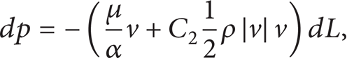
where C2 is the inertial resistance coefficient, and it can be ignored when Re<10; that is, C2 = 0. Thereby, the impedance in Figure 2 can be defined as the viscous resistance 1/α.
The one-dimensional flow state in which the gas flows in the showerhead face plate along z-direction can be described as follows.
Mass conservation equation:

Momentum sinks equation:

State equation for ideal gas:
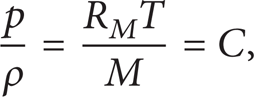
where R M is the gas constant (R M = 8.314 Jmol−1 K−1); M is the molar mass of N2 (M = 0.028 kg/mol). The showerhead face plate is considered as approximate isothermal domain, and the temperature is T, and then the C is a constant.
Analyzing the ith pair of monitor sites and synthesizing (2)∼(4), we can derivate that

where pin,ivin,i = pout,ivout,i = −CQ
m
(Q
m
is the gas mass flux through the ith monitor site on the input layer, unit: kg/m2s). The formula (5) reveals the relationship among the gas velocity, pressures of the monitor sites on input and output layer, respectively, and the impedance coefficient
3. Optimization Solution
3.1. Optimization Problem
Process uniformity reflects the coordinated uniformity among the all factors in the entire space of the wafer surface. When the process deviation occurs, we can adjust the distribution profile of one of the factors to offset the nonuniformity caused by the others and then to realize certain coordinated uniformity again. The vector showerhead has a relatively flexible potential for the control of the factor of gas mass transport profile; thereby a significant requirement is proposed which is how to quickly design a vector showerhead to make the gas flow profile approximate to an expected one.
The calculational model for the above-mentioned design problem is shown in Figure 3. The optimization problem is how to design the showerhead to make the gas radial velocity distribution profile, on the surface of h height above the pedestal in the reactor, approximate to vr,h* = V m f(r) + c; {r∈[0,R];0<h<H}, where f(r) is the profile function and V m and c are the scaling factor and translation factor, respectively.

Calculational model for the problem to be optimized.
3.2. Objective Function and Design Variables
We can adjust the impedance coefficient distribution profile on the showerhead face plate to make the vr,h continually approximate to the expected vr,h*, and thereby the objective function of the optimization problem can be defined as the relative profile approximation error on the entire surface, expressed as

The function of the objective function is different from the conventional one, and the formula (6) just plays the role of evaluation in the optimization solution but does not deduce the optimization direction. This mainly considers that evaluating the profile-characteristic objective function will greatly increase the degree of nonlinearity. The direction of this optimization problem will be elaborated in Section 3.4.
The design variables are defined as the impedance sequence
3.3. Optimization Principle
An iterative approximation method is very appropriate for the problem where design objective and variables are the continuous-characteristic profiles. Figure 4 illustrates a general principle of the solution for this type of optimization problem.

A general principle of the optimization solution.
In order to design a structure that can generate an expected physical field distribution profile, we guess an initial design model to start the iteration and then do simulation and obtain the profile error from comparing the physical field in the current model with the expected profile; if the error is not acceptable, then adjust the design variables to generate a new model; do the same work for the new model; run the iterative loop until an appropriate model is found. In this principle, the objective function is used to evaluate whether the profile error can be accepted.
3.4. Iterative Formula for PEF
The most important to realize in the above-mentioned optimization principle is how to adjust the design variables based on the unacceptable profile error. Next, in the view of the optimization problem shown in Figure 3, we construct the PEF formula using analytical method.
There are many ways to construct the PEF formula, but the key point is how to introduce the profile error efficiently. Generally speaking, the more accurate information of the system is included in the formula, the faster the iterative convergence rate will be. The above-mentioned formula (5) indicates that adjustment of the design variables will directly affect the local mass flux, so that it is appropriate to construct the PEF formula based on the gas mass flux and introduce the profile error in the form of the ratio of the two profiles, expressed as

where Qm,k is the gas mass flux distribution profile on the showerhead face plate of the current model, and Qm,k + 1 is of the new model moving towards optimized point in the design space. In this formula,
From formula (7), we can solve the gas mass flux profile Qm,k + 1 of the next expected new model. For a general model, a finite difference method can be employed to solve the Qm,k + 1; but for a two-dimensional axisymmetric model, an analytical solution exists, expressed as

When the profile Qm,k + 1 of the expected new model is obtained, we can evaluate the impedance sequence
3.5. Constraints
The impedance profile on the showerhead face plate cannot be uniquely determined just according to the physical field distribution in the partial domain of the reactor under certain determined boundary conditions. Therefore, a type of constraints should be found to restrict the impedance profile shifting. It is appropriate to make the average surface impedance of the showerhead face plate keep unchanged before and after the adjustment of the design variables.
From (2)∼(4), the average surface impedance can be deduced and expressed as

In order to make the new average surface impedance

Substituting the reciprocal [α]i,k + 1** of the corrected impedance sequence

Considering the iteration stability, we replace the Q
m
by the mass flux Qm,k in the current model, rather than the Qm,k + 1 in the new model. Thereby, the corrected impedance sequence
3.6. Iteration Control
Since the gas flow problem is highly nonlinear, the iterative calculation needs a certain control during the iterative loop. For this reason, we introduce the relaxation factor fr (0<f
r
<1) for the corrected impedance sequence

where [1/α]i,k is the optimized impedance sequence in the kth iteration step.
The relaxed impedance sequence

4. Results and Discussion
We use the proposed optimization solution to design a showerhead system, which can make the increasing magnitude of the gas radial velocity smaller and smaller so that we can repress the higher deposition rate caused by the other factors at the edge of the wafer. Set the critical surface on the 4 mm height above the pedestal and in the range of the center to 160 mm radius inside the reactor. Make the profile function f(r) = sin(r/R·π/2), r∈[0, 160 mm], h = 4 mm. Configure the value of the boundary conditions for the calculational model as follows.
N2 mass flow rate Qinlet = 5000'sccm, and gas temperature Tin = 25°C at the inlet.
A fixed pressure poutlet = 266 Pa at the outlet.
A fixed temperature T s = 400°C on the surface of the pedestal.
The other walls are considered as stationary wall, and the temperature Twall = 50°C.
In order to test the performance of the PEF optimization solution, we guess three initial cases for the design model to approximate the same expected velocity profile. Case 1 has an uniform impedance on the showerhead face plate and its value is 9.39 × 10+8 m−2. Case 2 has a linear distributed impedance, but the highest value is 1.5 × 10+9 m−2 at the center and decreased to 7 × 10+8 m−2 at the edge. Case 3 has a parabolic distributed impedance, and the values are both 7 × 10+8 m−2 at the center and the edge, and the highest value is 1.5 × 10+9 m−2 at the middle of them.
Before starting the iterative loop, we set the same average surface impedance
Figures 5, 7, and 9 show the evolution of the gas radial velocity profile at a distance of 4 mm above the pedestal over the iteration steps for the three cases, respectively. The trend of the profile evolution indicates that the gas velocity profile in the new model of every iteration step continually approximates to the expected one. Additionally, the gas radial velocity profile of the three guessed initial design models greatly deviate from the expected one, but they have well approximated to the expected profile after 6∼12 times to adjust the impedance sequence, and the relative error of the profile reduces from 25%∼15% to about 1%.

Case 1: Gas radial velocity profile, at a distance of 4 mm above the pedestal, approximating to the expected profile.
The optimization solution ran this case on a PC of CPU: Intel, 2.67 GHz, 32 bit and Memory: 2 G; the CFD simulation called the commercial software FLUENT code; the scale of this case was that about 45000 nodes were meshed for the model and N = 320 pairs of monitor sites were scattered for the impedance profile; for the three cases, the algorithm ran 6, 8, and 12 iterative steps, respectively; finally, the time cost in total was about 10∼20 min. Figure 11 shows the evolution of the relative error over the iteration steps, and it indicates that the algorithm has good stability and convergence rate for solving this problem.
Figures 6, 8, and 10 show the adjustment of the design variables with the iteration steps for the three cases, respectively. Finally, we obtained an appropriate profile for the impedance that made the gas velocity profile in the reactor well approximate to the expected profile, and the relative error was about 1% after 6∼12 iterative steps. Next, we should inversely map the impedance profile to the geometry configuration of the holes on the showerhead face plate. The topology and distribution density of the holes directly impact on the impedance, and the impedance [1/α] of a simple uniform porous media consisting of the cylindrical holes can be approximately expressed as

where d and L are the diameter and length of the hole, respectively, and f is the distribution density of the holes.

Case 1: The impedance [1/α] profile along the radial direction of the showerhead face plate during the iterations.

Case 2: Gas radial velocity profile, at a distance of 4 mm above the pedestal, approximating to the expected profile.

Case 2: The impedance [1/α] profile along the radial direction of the showerhead face plate during the iterations.

Case 3: Gas radial velocity profile, at a distance of 4 mm above the pedestal, approximating to the expected profile.

Case 3: The impedance [1/α] profile along the radial direction of the showerhead face plate during the iterations.

Relative error of the velocity profile approximating to the expected profile during the iterations.
The formula (14) indicates that we can find infinite variety of combinations of the geometry configuration and distribution density of the holes that can make the impedance distribution demand a certain required profile, such as by changing the diameter or distribution or topology or the combine methods of the above three. Considering the reusability of the design knowledge and the economy of the manufacturing, we reuse the typical hexagonal pattern to distribute the holes and control the drilling depth of the stepped holes to adjust the impedance.
The stepped-hole-characteristic porous plate can be approximately regarded as sequence connected two-layer perforated plates consisting of A and B cylindrical holes, respectively; thereby L/α = L1/α1 + (L-L1)/α2, where 1/α1, 1/α2, and 1/α are the impedance of the top layer, bottom layer, and the sequence connected body, respectively. The holes distribution density f as Figure 12 shows can be expressed as


Regular hexagonal pattern of stepped holes geometry configuration on the showerhead face plate.
Here, from the formulas (14) and (15), we can easily obtain the functional relationship between the geometry parameters of the stepped holes and the impedance. When the thickness of the showerhead face plate L = 8 mm; hole spacing l = 5 mm; fixed diameters d1 = 2 mm; and d2 = 0.8 mm, we can adjust the depth L1 of the A segment to make the impedance profile coincide with the optimal result in Figure 6. Figure 13 shows the functional relationship between the drilling depth L1 and the radial position r.

Drilling depth in stepped holes as a function of radial position.
5. Conclusions
A PEF optimization solution was proposed and used to design the vector showerhead in a vertical reactor, and it made the gas velocity profile in the critical surface continually approximate to the expected profile. In the test case, optimization solution tried to adjust the impedance profile 6 times to make the relative profile error, which the gas radial velocity in the critical surface approximated to the sinusoidal profile, reduced from 25%∼15% to about 1%. Finally, according to the optimized impedance profile, a stepped-hole showerhead was designed.
The work of this paper shows a novel optimization solution, which deals with the problem whose design variable and objective are a continuous profile. This solution employs cyclic iterative approximation mode and constructs the PEF to adjust the design variable sequence to make the specific physical field in the critical domain continually approximate the expected profile. Except the above-mentioned characteristics, the solution does not ask special requirement for the guessed initial design model, and the time cost is linear correlation with the length of the design variable sequence so that the design variable profile can be discretized in very high resolution. Additionally, one of the key points of this solution is how to construct an efficient PEF, but the way of constructing PEF has a certain relationship with the design object at present; therefore in order to broaden the practicality of this solution, the generalized method for PEF construction needs to be studied sequentially.
The PEF solution is proposed to aim at the accurate continuous design optimization and control problem, especially such as how to adjust and control the physical fields distribution by structure design or device control. As for different physical regimes, it just needs to reconstruct the iterative formula, and the solution architecture can be inherited. It is worth mentioning that a rough approximate one can also successfully drive the PEF in general, though the iterative formula dramatically impacts on its performance.
Footnotes
Appendix
Under the boundary condition of 5000'sccm of N2 mass flow at the inlet, the average Reynolds number in the hole on the showerhead face plate is calculated as
List of Symbols
Conflict of Interests
The authors declare that there is no conflict of interests regarding the publication of this paper.
Acknowledgments
The authors would like to thank the National Science & Technology Major Project (no. 02) of the MOST (no. 2011ZX02403) and Shenyang Piotech Co., LTD, China.