
Abstract
To solve the problem of collaborative engineering changes of models distributed in heterogeneous design platforms, a “model to model” perception methodology is proposed in this paper. A self-management collaborative architecture is presented by peer to peer architecture and multiagent system. The network addresses correlation between heterogeneous platforms is built up by the perception router ontology. In the same way, the correlation between design models is described by the feature relation ontology. The design changes are encapsulated by the model modification ontology. Along with the ontology above, the design change search method is devised to catch the geometric changes; the influence search method is proposed to discover the influenced design feature and the design change adapting method is used to preserve the correlation coherence after perception. Through the work, the conventional design perception mode among designers has transformed into direct perception among models instead.
1. Introduction
The design of complicated mechanical products is an iterative process during which modification is inescapable. Geometric model is carrier of design ideas while its changes always bring an effect among downstream design model. For instance, the finite element partition of the analytic model depends on design model's geometry. Machining surface is a required input for numerical control programming while its changes would lead tool path to alter. The structure of manufacturing equipment, like fixture design, is similar to the product shape in some respects. Locators and clamps need to be matched with the shape belonging to the design model [1, 2]. Such collaborative requirements cannot live without the change perception. As humans perceive the activities from others, the collaborative perception is defined as the ability of designing model including sending, obtaining, and disposing design changes in heterogeneous platforms spontaneously.
As a matter of fact, modern commercial computer-aided products already have collaborative perception abilities as shown in Figure 1. The main methods include the following.
Master model method makes the geometric model as master model and builds relationship with other disciplinary model [3]. When the master model is changed, the referenced models are changed synchronously. In this way, geometric consistency can be maintained between multidisciplinary downstream models belonging to the same master model. For example, a geometric modification can drive related finite element models to change partition basis. However, it will not drive other master models to change unless they have design relationship. We classify it into self-perception (SP) type.
Updated method can update the geometric models at scheduled time. It only updates geometric models which are modified but cannot impact others. So it is also of SP type [4].
Assembly reference method supports referring geometric element from other components. When the referenced geometric element is modified, the geometry of relevant component will change at the same time. This method realizes design change broadcast between different components, so we classify it into interaction perception (IP) type. But it is confined to the same CAD platform [5].
Constraint method creates the constraint relationship between models via parameter expressions or geometry constraints [6]. When model's geometry is changed, the other relevant model will be changed automatically according to constrain rule. This method is also of IP type.
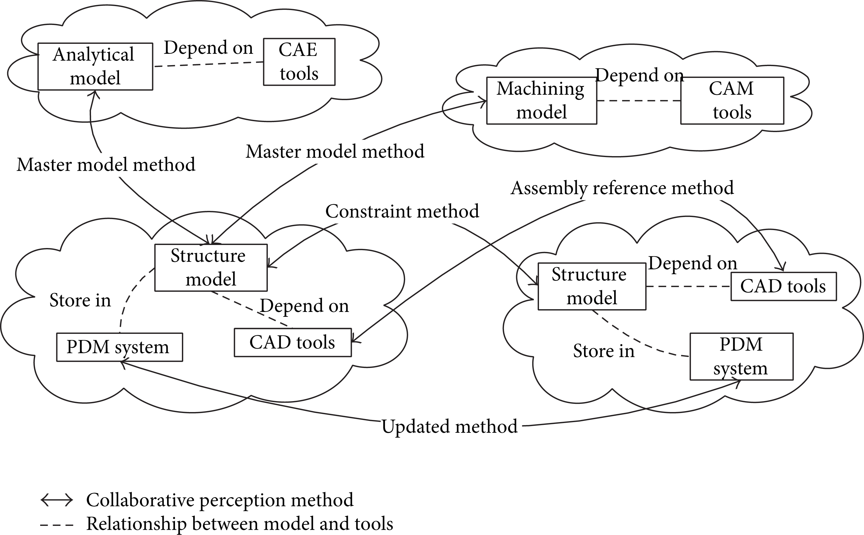
The collaborative perception method status.
In this paper, a new model perception methodology is proposed to promote the design models to intelligent model which has active perception abilities. The proposed perception abilities here are not real organism sensed but means heterogeneous design model can broadcast its changes actively and get influences from other model automatically. With this research, the solved scientific problem is to promote design model only as the change carrier to a smart model with change handling ability. The solved engineering problem is making design model to capture change automatically and broadcast change to affected model belonging to heterogeneous platforms. Traditional “designer to designer” perception mode will be changed to “model to model” mode, and therewith designers can be avoided getting involved into maintaining design coherence. But it is important to note that design conflict is not mentioned in this paper. It would be researched later referring to other achievements about engineering change.
The rest of this paper is organized as follows. Section 2 presents a brief review of the literature that is related to perception of engineering change and design change. In Section 3, the framework of collaborative communication is put forward; the work flow of perception information is given meanwhile. In the same section, three kinds of ontology are proposed to solve heterogeneous platform interoperation. The key method for model perception is proposed in Section 4. An example is given in Section 5, which is followed by concluding remarks in Section 6.
2. Related Research
2.1. The Propagation of Collaborative Engineering Change
Collaborative design of complex product is implemented by groups distributed in different areas. Iterative design process is improvement process of relative components in essence, that is collaborative engineering change [7]. The research hotspot includes engineering change propagation predictability and engineering change implement method. Engineering change predictability based on matrix or network is studied mostly. Steward [8] proposed design structure matrix (DSM) in 1981. Clarkson et al. [9] predict the change possibility, from a subsystem to another one, by the matrix of the impact possibility. But these approaches are too fuzz to express constrains between elements in DSM, which leads to imprecise predictability. Another intuitive predictability approach is based on complex network. Ma and Gujarathi [10] expresses the product feature relationship as constrain network and the corresponding change broadcast analysis approach is proposed. Zhang et al. [11] prompt the algorithm of Ma's and propose the design change broadcast approach based on assembly constrain network. It is suitable for broadcast trend analysis but difficult to analyze broadcast detail because of weakness of complex network. The above-mentioned research can be referenced to build relationship between distributed design models. The relationship can be defined before design or mined from law of change influence between components. For the implement approach of engineering change, a parameter-based approach is presented which focused on building up the network of the parameters relationship between different models [12, 13]. By the parameter network, design knowledge could be possibly accumulated for implement design change propagation. Ma et al. [14] introduced a new method of maintaining modeling-associative relations by a unified feature modeling scheme and elaborated a change propagation method for the information consistency control among several product lifecycle stages. Liang and Guodong [15] analyzed characteristics of multidiscipline collaborative design of products. A multilevel relationship including semantic level, structure level, and management level is presented and the concept of the discipline view model is given. Fan and Gui [16] develop a method to search for change propagation paths based on parameter linkage perspective, through which the propagation mechanism of changes is analyzed. It is found that the parameter linkages in designs can be organized in a structured manner.
In conclusion, engineering change propagation based on parameter relationship is an important way for maintaining data consistency, but it is not considering that heterogeneous digital platform distributed in different area will bring difficulty. This paper just prompts the jam of collaborative design under the distributed heterogeneous environment.
2.2. The Research of Design Change Perception
Multiagent technology has been widely used for supporting cooperation or enhancing interoperability between traditional computational tools. It provides the self-organized ability, communication ability, and dynamic combination ability for collaborative participant. Peer-to-peer technology focuses on sharing resources among collaborative participants while it discards the shortcomings of B/S (browse/server) or C/S (client/server) technologies. Fan et al. [17] presented a distributed collaborative design framework with a hybrid of grid and peer-to-peer technology by which resource discovery can be easily implemented. Yin et al. [18] attempted to use a peer-to-peer based multiagent framework for decentralized grid workflow management in collaborative design. Ren et al. [19] built a collaborative MDO framework based on multiagent systems which is in charge of the collaborative communication between different design systems. Reza [20] gave dynamic of interactions for the state-problems emergence. The theory is verified by using multiagents technology. These studies show that both peer-to-peer and multiagent technologies, popular for design data exchange, are suitable for design change perception communication.
At present, the major design perception type includes data perception and behavior perception. For data perception, in some commercial product data management system, check-out and check-in functions are provided to keep design data from illegal operation; anybody can get last valid version from management system to know other's work. Google website also provides a document management service on the network which allows users to edit the same document simultaneously. Similarly, Lin et al. [21] provided a collaborative editing system which allows coauthors to edit a shared view of a single design document simultaneously at different locations. It supports distributed editing of replicated compound documents and integrates notification mechanisms by which coauthors can inform each other about document change. Tam and Greenberg [22] developed a system, which could articulate the document modification, accounted for providing users with different perspectives including an artifact-based view, a person-based view, and a workspace-based view for who-what-where-when-how-why problems. By this way, design change awareness was built up for document collaboration.
Except the research about documentary change perception, geometry change perception is a most concerned problem in structure design. Chu et al. [23] researched a 3D streaming method based on multi-LOD geometric models for network application. It helps to transfer collaborative design model according to current requirements. In order to reduce the amount of data transmission, Wu and Sarma [24] developed a method to incrementally update the B-Rep of a design model based on a cellular representation in a distributed environment. The method could identify and extract those regions that had been modified by a designer which can enhance collaborative perception response speed. Furthermore, Li et al. [25] proposed a distributed feature manipulation mechanism to filter the useless information on a working part. During a codesign activity, it was used to avoid retransferring the unnecessary complete large-size CAD files each time. In addition, geometric lightweight is also a pregnant research for geometry perception. Lee et al. [26] proposed a shape abstracting mechanism to provide a lightweight abstracted attributed B-rep (AAB) on clients to represent feature-based models which were stored on a server. By this lightweight representation, collaborative actors would get a better experience on geometric perception. As all mentioned above, the perception research emphasis focuses on providing intuitive design state for designers. Some achievements are available to human perception but not involving perception between heterogeneous models.
As another important perception type, text chat is a well-known method for behavior perception. Beside text chat, other intensive behavior perception tools, bringing out multiform behavior awareness ability, are researched widely. Shen et al. [27, 28] presented a collaborative system in which users could browse the product history, such as previous modification processes and feature information being discusses, which is highlighted to attract the users. Subsequently, the collaborative behavior perception using augmented reality technology is researched. Via this way, designer can observe the design behavior in real time. Zadeh et al. [29] presents a new CAD manipulation mode depending on haptic device. It can capture designer's behavior and present force feedback to user's hand. Schrefl et al. [30] define the collaborative behavior according to cooperation contract and define the collaborative method between collaborative objects. It can be found that the above research focuses on capturing collaborative working behavior to present to human. But if you take design model as a smart model with perception ability, it is absent of related research between them.
In summary, existing collaborative perception methodologies are presented based on just taking design model as a carrier of design result but not having interactive ability. This paper wants to change this situation by building a new perception mode between distributed design models.
3. The Architecture of “Model to Model” Design Change Perception
3.1. “Model to Model” Perception Ontology Construction
According to the content of design change, perception type can be divided into nongeometric perception and geometric perception. Nongeometric perception is suitable for attribute information change like material property, physical property, and so forth. Geometric perception, which broadcasts the geometric changes between design models, is suitable for maintaining geometric coherence [17]. In this paper, some declarations are given firstly. The design models are supposed to be distributed in heterogeneous digital platforms, such as product data management (PDM) platforms and computer aided design (CAD) platforms. Likewise, the changed design model is called active model, and the influenced design model is called passive model in the rest of the paper. To implement perception abilities independent of a certain digital platform, there is some neutral ontology constructed as follows [31].
3.1.1. Model Modification Ontology (MMO)
The description of modification with neutral format occurred on active model. It is divided into nongeometric modification ontology and geometric modification ontology. Once model is changed, the MMO is created by the execution agent with using design change searching method given later.
Nongeometric modification ontology is defined as a triple group:

Geometric modification ontology is defined as a quadruple group:
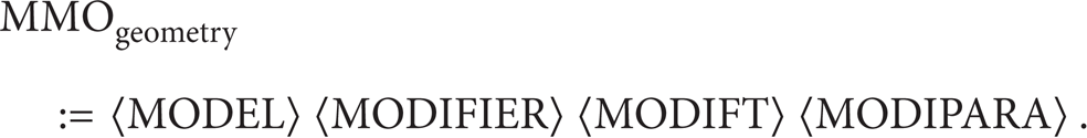
MODEL is the modified design model. MODIFT is the changed feature in active model. MODIPARA is the modified parameter. MODIFIER is the unique identification of the designer. MODICONTENT is the content of changed attribute information.
3.1.2. Perception Router Ontology (PRO)
The description of influenced models address with neutral format: the passive models can be found out via looking up it. The PRO is created according to the protocol confirmed by the designers in advance. It is defined as a triple group:

IP is the net address of the PDM platform which stores the influenced model. ADDRESS is the unique identification of models in the PDM platform. TYPE is the unique identification of special PDM platform type.
3.1.3. Feature Relation Ontology (FRO)
The description of influenced features on passive model: the relationship of model features can be gotten through looking up in FRO. Similarly, the FRO is created by designer according to protocol confirmed in advance. It depends on a quintuple group:
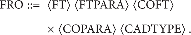
FT is the feature which is changed. FTPARA is the parameter of the changed feature. COFT is the feature influenced by modified models. COPARA is the feature parameter of the influenced feature. CADTYPE is the type of CAD platform which the influenced model belongs to.
3.1.4. Model Amendment Relation Ontology (MARO)
The description of changed relationship between related models with neutral format: after design change is confirmed, the MARO is created by the execution agent. It is defined as an eight-element group:

MODEL is the passive model that is modified. ADDRESS is the location of distributed PDM platform. PDMTYPE is the type of PDM platform. CADTYPE is the type of CAD platform. PDMIP is the net address of PDM platform. MODITYPE is the type of design change including add, delete, and modify. FEATURE is the information of modified feature. PARA is the information of modified parameter.
Above collaborative perception ontology can be described by OWL or XML and other technologies. Similarly, the ontology can be abstracted by the object-oriented approach. Some classes are constructed to express ontology shown in Figure 2 [32].
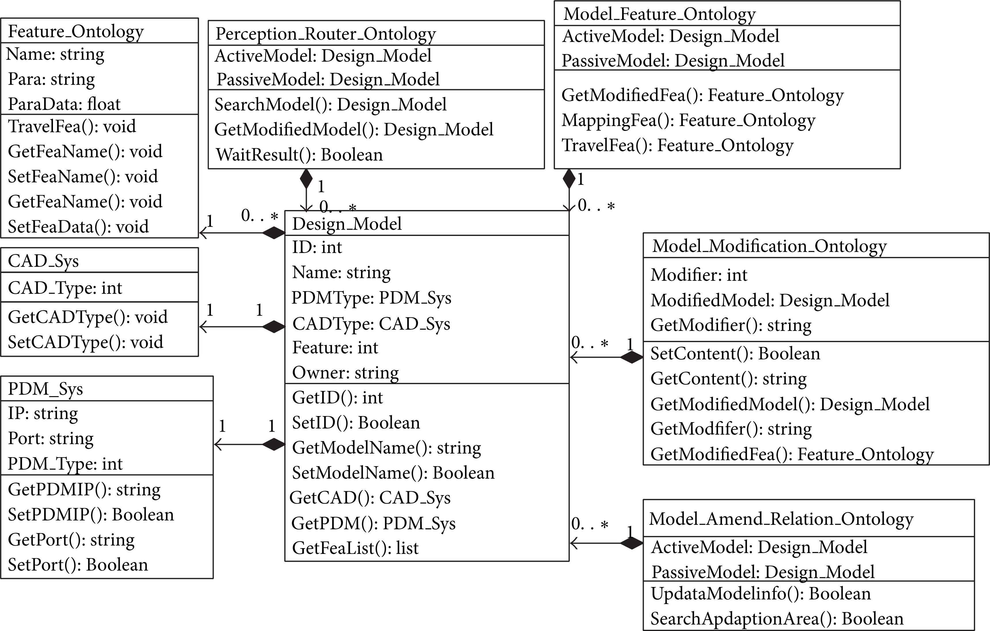
The collaborative perception ontology.
The class named PDM_Sys is used to record the model storage system. The class named CAD_Sys is applied to describe the model format which determines feature parsing method. The class named Feature_Ontology is applied to record the design feature information. All of these are composited in the class named Design_Model which represents the distributed design models. The class named Perception_Router_Ontology is built up for the passive model searching. The class named Model_Feature_Ontology is used to establish the design relationship among features which are based on class Feature_Ontology. The class named Model_Modification_Ontology is used to describe the content about design modification. The class named Model_Amend_Relation_Ontology is to keep the coherence of design relationship. In practice, ontology classes are always encapsulated into XML file in network environment.
The PRO and FRO that can be acquired from the design skeleton embody the design correlation between design models when we employ popular top-down design method. In other words, the PRO and the FRO retain the correlation on the distributed network but not only on CAD model any longer.
3.2. “Model to Model” Perception Architecture Based on Multiagents Mode
To make design models be aware of each other, a framework based on P2P architecture is established with deploying the listener agent, router agent, and execution agent on the collaborative node.
Every router agent maintains a PRO file for maintaining relationship between related design models. Any model which has geometric relationship with others maintains a FRO file for itself. It is managed by execution agent. After comparing the modified design models with original ones, the MMO file is created by execution agent. The MARO file is maintained by every listener agent when relationship is changed after modification. The framework of model perception is shown in Figure 3.

The framework of model perception based on multiagents.
In Figure 3, node A, node B, and node C mean the collaborative node which is the virtual participant of collaborative design. It is equal situation for every collaborative node in the P2P architecture which is sender and receiver of design change message. In every node, a router agent, a listener agent, and an execution agent are built up to contact digital platform such as PDM or CAD software.
3.2.1. The Execution Agent
It resides in the collaborative node with in charge of interact with design model. Through the interfaces provided by digital platform, execution agent can catch the change from modified model. Meanwhile, it creates the MMO according to FRO and feedback to router agent.
3.2.2. The Router Agent
It resides in the collaborative node in charge of broadcast design change and maintains PRO file. When it received a broadcast instruction, the MMO is transferred to relate collaborative node according to PRO.
3.2.3. The Listener Agent
It resides in the collaborative node in charge of receiving MMO from other collaborative nodes. When it receives the modification message, the execution agent is invoked to promote the designer or dispose automatically. On the other hand, listener agent maintains an MARO file. When the design relationship is changed, the listener agent will modify the MRAO file to keep it in coherence.
3.2.4. Product Management Platform
It is the warehouse of the design model which provides the interface for add-value development. Any design model can be stored and found out by its address.
3.2.5. Computer Aided Design Tool
It is the professional tool for product design which provides the interface for add-value development also. In general, geometric modeling tools, engineering analysis tools, and even machining planning tools can be classified into this type of tools.
3.3. The Workflow of “Model to Model” Perception
Before the explanation of model perception workflow, there are some definitions that are declared.
Definition 1. The collaborative node stored active model is named active node. The collaborative node stored passive model is named passive node.
Definition 2. The changed geometric structure features are recorded as a set named fea i , i∈N; the changed nongeometric design attributes are recorded as attri j , j∈N.
Definition 3. The geometric change ontology of active model is named FD and the nongeometric change ontology is named MD.
3.3.1. Design Changes Find
When a design model is modified and saved in CAD software, the execution agent on the active node is invoked. It achieves the geometric change by the geometric change searching method in Section 4. The nongeometric change can be achieved by comparing attributes value.
The execution agent catches the changed geometric feature set fea i . It is encapsulated into MD subsequently. For different design platforms, the execution agent uses different development interfaces to manipulate design model. But MD is in the unified form without regard to difference of design platforms.
The execution agent catches the nongeometric attribute changes that are attri j . It is encapsulated into FD subsequently. For different design platforms, the same attribute value maybe has different representations. So FD should be translated into standard ontology form.
The MD and FD are combined as MMO that is sent to local router agent.
3.3.2. Design Change Broadcast
When the MMO is received from local execution agent, router agent parses the MMO to get active model identification.
According to active model identification, the router agent looks up the PRO file to get the passive models identification related to active model.
The network addresses of all passive models are achieved from PRO file by router agent.
According to network address of passive model, the MMO is transferred to listener agent on the other passive node.
3.3.3. Geometric Change Perception Disposes
On the passive node, the listener agent takes charge of receiving the MMO. If any MMO is received, it would be extracted to search the passive model according to its identification.
The passive model is loaded to execution agent according to its identification. Traverse the fea i in the FD, and execution agent finds out the influenced geometric feature by looking up the FRO.
The influenced geometric parameters are found out by looking up the FRO.
A suggestion is created by execution agent. It makes the influenced geometric features with highlight; influenced design parameters and possible modification schemes are proposed in text.
Whether the influenced model is modified or not and which modification scheme to adopt are decided by designer.
3.3.4. Nongeometric Change Perception Disposes
The listener agent received the MMO. The MD is extracted to search the passive model according to its identification.
The passive model is loaded to execution agent according to its identification.
The MD is transferred to execution agent. Traverse the attri j in the MD, and execution agent finds out the influenced attribute in passive model.
A nongeometric design change report is created by execution agent. If the change item is authorized by designer, the passive model is changed subsequently. If the change item is refused, the passive model is not changed.
3.3.5. Perception Self-Adaption
The execution agent on the influenced node collects the actual status of passive models.
The execution agent creates the MARO file according to actual modification.
The execution agent sends the MARO to local router agent.
The router agent on the passive node modifies the local PRO.
The execution agent on the passive node modifies the corresponding FRO description belonging to the passive model.
The router agent on the passive design node takes charge of sending the MARO back to the active node by looking up PRO.
The listener agent on the active node receives the MARO which is sent to the local execution agent and the router agent in addition.
The router agent on the active node modifies the local PRO.
The execution agent on the active node modifies the corresponding FRO description belonging to the active model.
In Figure 4, the workflow of the perception broadcast is visually described. The number is in correspondence with the above steps. In Figure 5, the workflow of the perception self-adaption is described.

The workflow of the perception broadcast.

The workflow of the perception self-adaption.
4. The Key Methods for “Model to Model” Perception
How to get the design changes from the active model automatically is solved by design change search method. The sequence diagram of the search method is shown in Figure 6. The entities in diagram are listed in Table 1.
The entities in the sequence diagram.
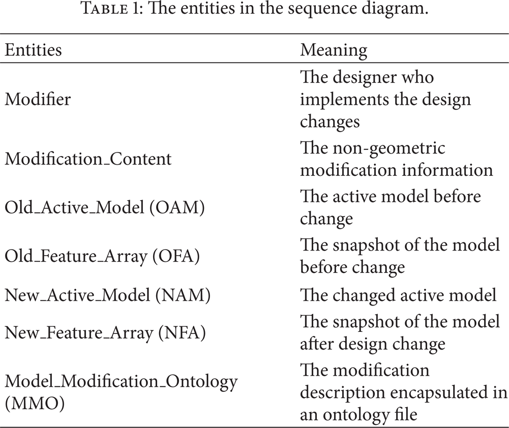
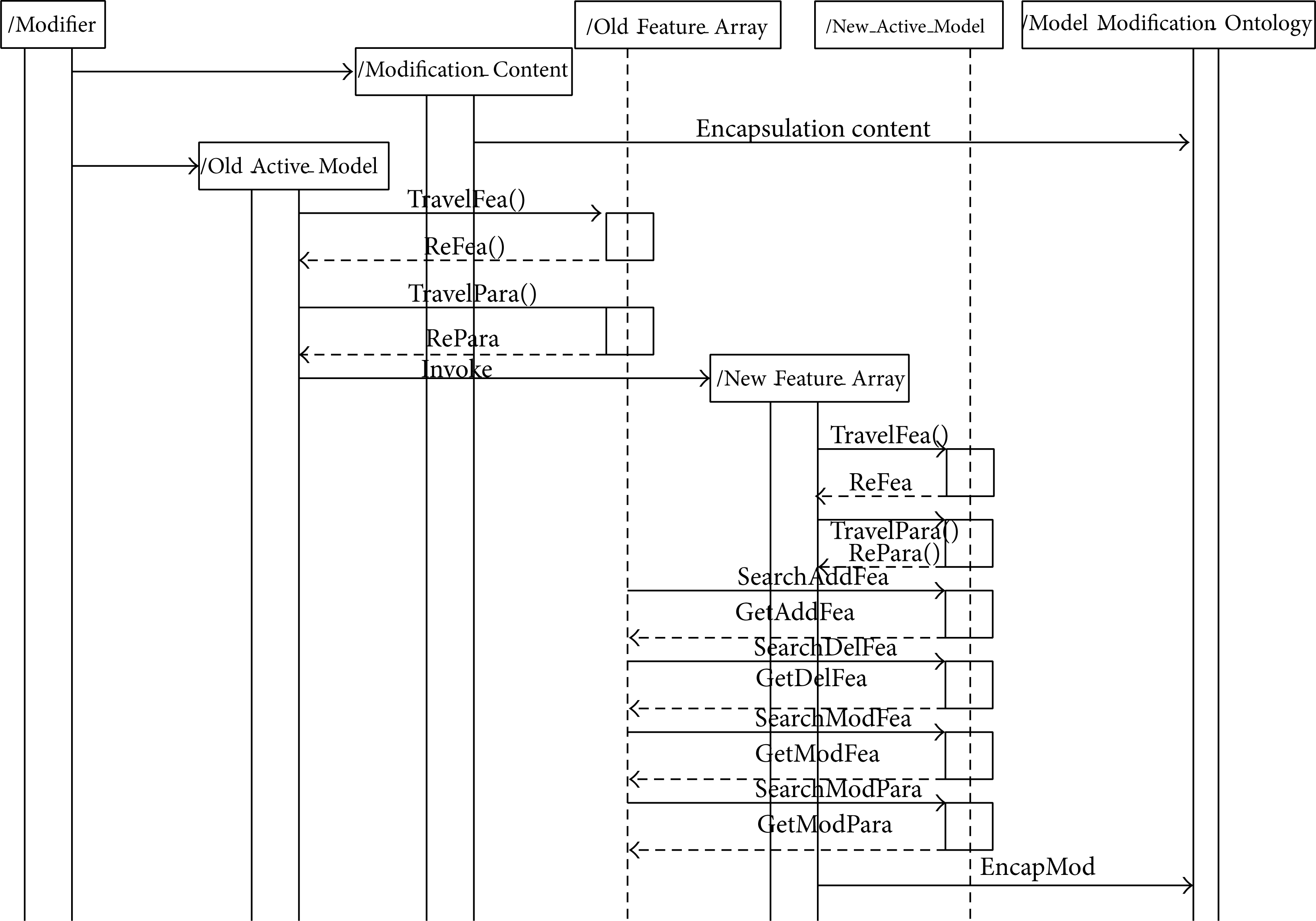
The sequence diagram of design change search method.
Design change search method can be divided into nongeometric type and geometric type. Nongeometric type depends on comparing standard textual value of model attribute before and after modification. The existing textual comparison achievement can be referred to realize this type search fully [33]. Geometric type depends on comparing the difference of active model's geometry before and after modification automatically [34]. For this purpose, a geometric change search method is proposed as follows especially.
Open the active model which is corresponding to OAM.
The geometric snapshot is created for active model. It is corresponding to OFA which includes feature array named m_arrayOldFea and parameter array named m_arrayOldPara. The m_arrayOldFea records all features belonging to active model. The m_arrayOldPara records all parameters in every feature.
After modification, the active model is changed to a new model corresponding to NAM.
A new snapshot is created for NAM. It is corresponding to NFA which includes feature array named m_arrayNewFea and parameter array named m_arrayNewPara. The structure of NFA is equal to OFA.
After comparing the m_arrayOldFea and the m_arrayNewFea, the added features and deleted features are found out to put into m_arrayAddFea and m_arrayDelFea, respectively.
The geometric parameters corresponding to the features in m_arrayAddFea are found out in m_arrayNewPara. And these parameters are put into array named m_arrayAddPara.
The feature parameters corresponding to the features in m_arrayDelFea are found out in m_arrayOldPara. And these parameters are put into array named m_arrayDelPara.
The features both existing in m_arrayOldFea and m_arrayNewFea are found out to put into array named m_arraySavedFea.
Traverse the elements in m_arraySavedFea, and the parameter value belongs to the retrieved features, both existing in m_arrayOldFea and m_arrayNewFea, which are compared. If the parameter value is changed, and the features to which it belongs will be put into array named m_arrayModiFea.
The feature parameters, belonging to the features in m_arrayModiFea, are found out from m_arrayNewPara and put into array named m_arrayModiPara.
When the searching is completed, the changed geometric features are put into m_arrayAddFea, m_arrayDelFea, and m_arrayModiFea. Their corresponding parameters are put into m_arrayAddPara, m_arrayDelPara, and m_arrayModiPara. As a result, they are corresponding to MMO.
The design change broadcast relies on the passive model searching and influences feature locating. The change broadcasting method is in charge of searching passive models and locating the design change. The nongeometric change broadcast is used to prompt designer to decide whether the design attributes modifies or not. The geometric change broadcast is applied to change the passive model's geometry automatically under the permission. The sequence diagram of the change broadcast method is shown in Figure 7. The entities of influence search method are listed in Table 2.
The entities in the sequence diagram.

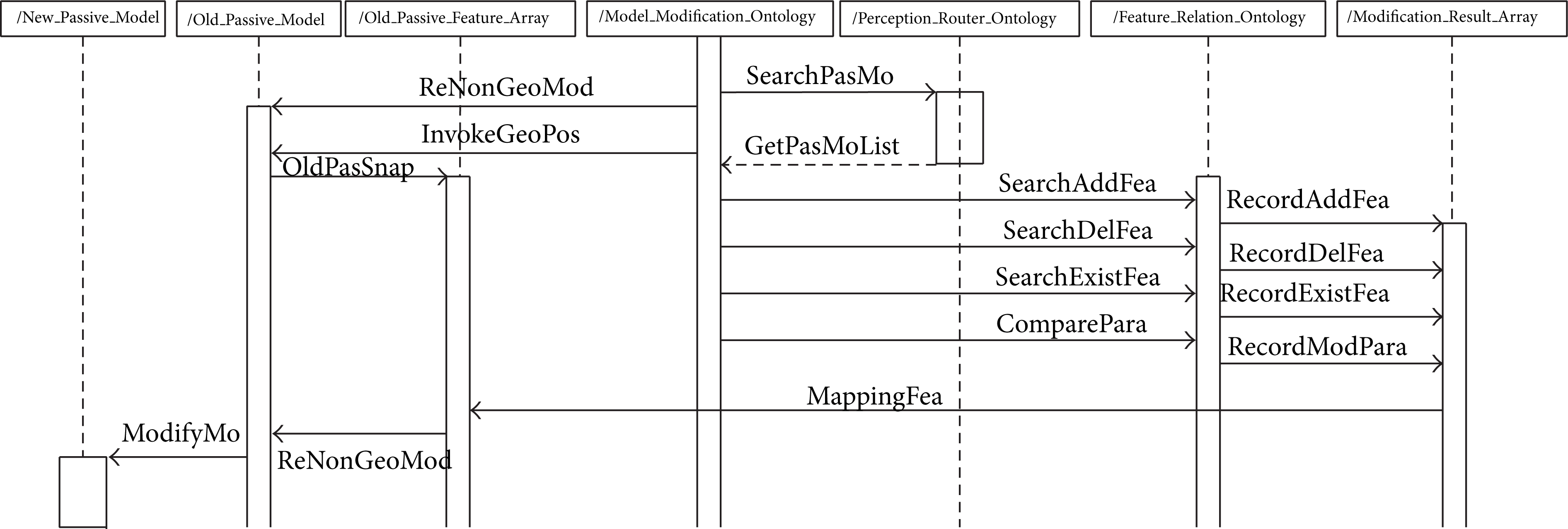
The change broadcast method sequence diagram.
The relationship between distributed models, which is recorded in PRO, is the regulation of passive model searching. As the searching result, the passive models’ addresses are found out and the modification contents are sent to them as well. If nongeometric change occurred, the textual change content is reasoned out for passive model and this can cue the designers. If geometric change occurred, the passive model's change schemes are gotten by the geometric locating search method. If the scheme is allowed, the geometry of the passive model is updated according to confirmed MMO. This paper focuses on the geometric locating search method as follows.
The passive model is opened which is named OPM.
The snapshot of passive model is created. It includes the feature array named m_arrayFea corresponding to OPFA and feature parameter array named m_arrayPara. m_arrayFea records all features belonging to passive model. m_arrayPara records all parameters in every feature.
When the MMO is parsed, the added features are put into array named m_arrayAddFea; the deleted features are put into array named m_arrayDelFea; the changed features are put into array named m_arrayModiFea. The added parameters are put into m_arrayAddPara; the deleted parameters are put into m_arrayDelPara; the modified parameters are put into m_arrayModiPara.
Traverse the FRO maintained by the passive model, and the features from m_arrayFea, related to the features in m_arrayModiFea, are put into array m_arrayRelModFea.
The parameters from m_arrayPara, related to the parameters belonging to m_arrayRelModiFea, are put into array m_arrayRelModiPara.
Traverse the FRO maintained by the passive model, and the features from m_arrayFea, related to the features in m_arrayDelFea, are put into array m_arrayRelDelFea.
The parameters from m_arrayPara, related to the parameters belonging to m_arrayRelDelFea, are put into array m_arrayRelDelPara.
After changing feature searching, the influenced features description, including m_arrayRelModFea, m_arrayRelDelFea, and m_arrayAddFea, is corresponding to MRA.
How to keep the coherence of design relationship is a critical technology for “model to model” perception which determines the validity of PRO and FRO [13]. If the modification is confirmed, the PRO and FRO of influenced models need to be updated. The change self-adapting method is proposed in Figure 8. The entities of change self-adapting method are listed in Table 3.
The entities in the sequence diagram.


The sequence diagram of change self-adapting method.
The modification of the passive model is encapsulated into MARO after model snapshot comparison. According to MARO, the PFRO of the passive model is modified at first. Following, the active models and network address are queried out from the PPRO. The relevant features needing to be modified are gotten from the PFRO. Then, the FRO of active model is changed. At last, the PRO of the active model and passive model is changed. The self-adaption method is shown as follows.
The scheme of modification is allowed by designer.
According to the scheme, the added features are put into array named m_arrayAddFea; the deleted features are put into array named m_arrayDelFea; the modified features are put into array named m_arrayModiFea.
The relative models related to passive model are found out by looking up PPRO. The searched models are put into array named m_arrayRelModel.
The relative features of modification on the passive models are found out by looking up PFRO. The searched features are put into array named m_arrayRelFea. The m_arrayRelModel and m_arrayRelFea are combined as MARO.
Traverse the elements of the m_arrayRelModel, and the MARO is transferred back to active model.
According to MARO, the m_arrayRelModel is used to update the corresponding node in the PPRO. The m_arrayRelFea is used to update the corresponding node in the PFRO.
According to MARO whose active model was received, the m_arrayRelModel is used to update the corresponding node in the APRO. The m_arrayRelFea is used to update the corresponding node in the AFRO.
5. Examples
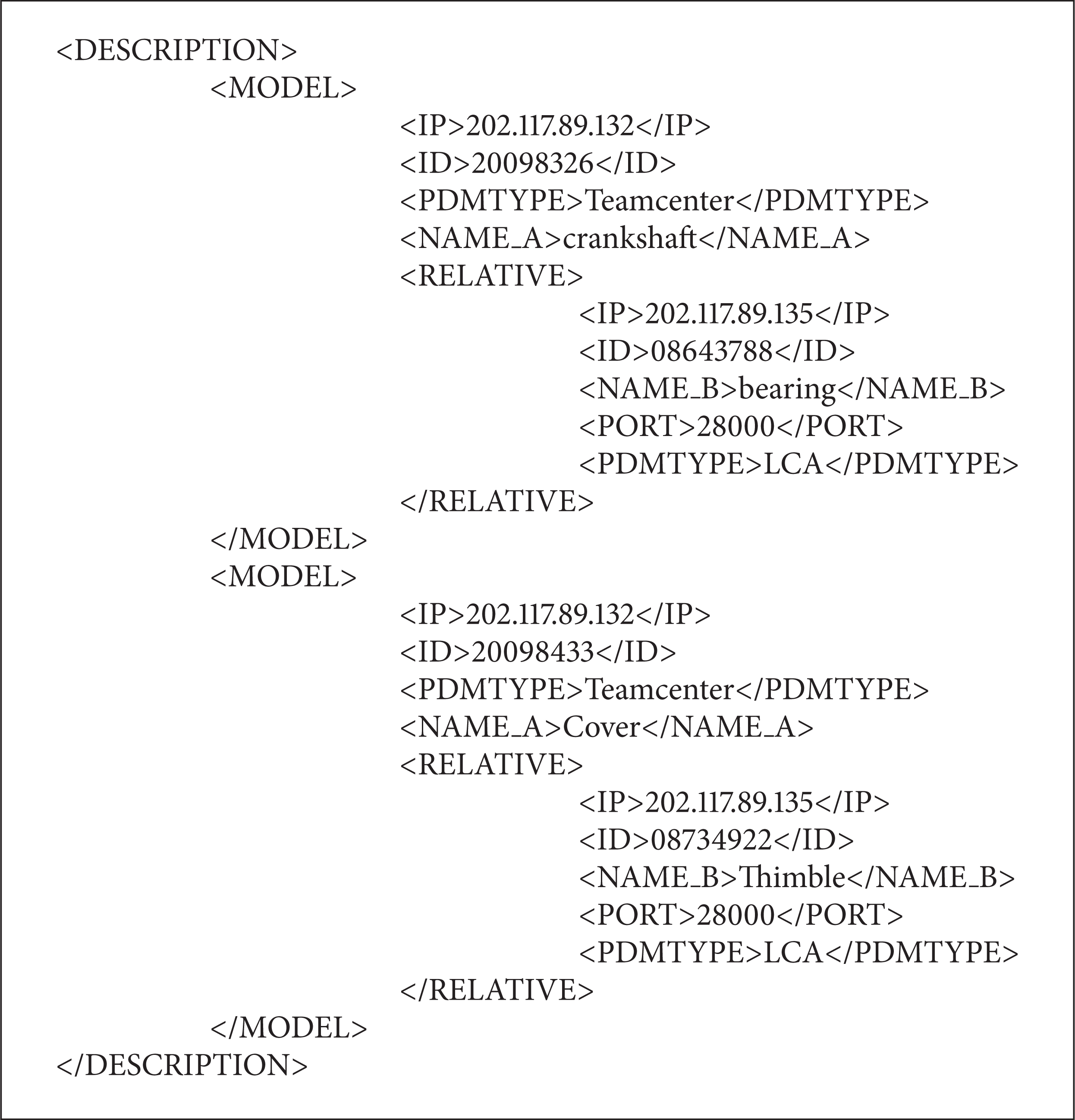
The aircraft is a typical complicated product maybe designed by several teams distributed in different commercial digital platforms. For example, the part named COVER and THIMBLE has various design relationships. The COVER is modeled by Dassault CATIA stored in Teamcenter platform with assigned ID 20098433 and the THIMBLE is modeled by Siemens NX stored in VPM platform with assigned ID 08734922. The relationship between both parts is listed in Table 4. In this example, design feature only means the geometric modeling feature in commercial CAD tools. It is not suitable for analytical model in engineering analysis. The attribute only means the defined attribute instead of the whole attribute set of analysis object. The parameter only means the geometric parameter to determine design model geometric structure.
The relationship of both parts.
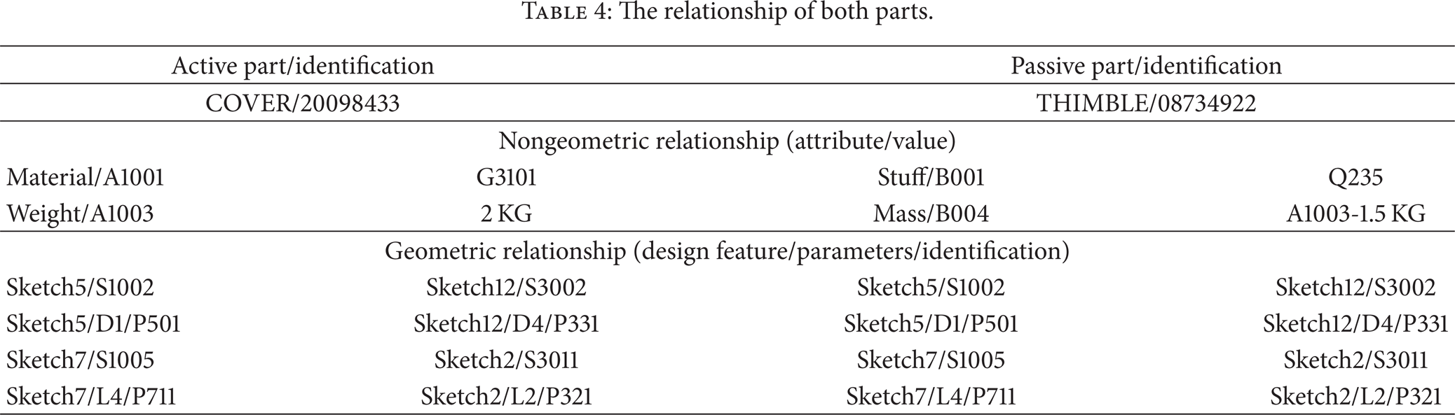
Two groups of attributes belong to the COVER and the THIMBLE, “Material” with “Stuff” and attribute “Weight” with “Mass”, which have the relationship as shown in Table 4. Similarly, two parts have geometric relationship that the parameter “D1” in geometric feature “Sketch5” keeps pace with the parameter “D4” in geometric feature “Sketch12.” Likewise, the “L4” in “Sketch7” keeps pace with “L2” in “Sketch2.”
It is worth noting that the model relationship of distributed design models can be set up by PRO which is shown as in Algorithm 1. The geometric relationship between design models can be set up by FRO which is shown as in Algorithm 2.
The description file of the PRO.

The description file of the FRO.
For nongeometric change, when the attribute “Weight” changed with design model modification, in the active model with ID 20098433, the changed attribute value is captured by execution agent. It is transferred to the listener agent on the passive node by looking up PRO. When passive model with ID 08734922 is found out, a hint about active model's change will be proposed to the owner of passive model for deciding whether to change the attribute “Mass” or not.
For geometric change, the designer modifies the COVER. When the parameter named D1 in the sketch 5 is changed from 548 to 540, we can describe the modification as in Algorithm 3. The active model's modification description is captured by the listener agent on the influenced collaborative node and it is sent to the performance agent subsequently. The performance agent looks up in the FRO description and finds out that the parameter D4, which is in the sketch 12 of model 08734922, should be modified from 548 to 540. This will be a notice sent to the owner of the model with ID 08734922, that is, THIMBLE. When the modification is completed, perception message is rewritten back to the node with modification occurring. The MARO can be described as in Algorithm 4. When the perception is completed, it will be found that COVER and THIMBLE remain the coherence about parameters in geometric features.

The description file of the MMO.

The description file of the MARO.
If design feature or model is modified, the PRO and the FRO will be changed correspondingly. However, only the relevant parameter's value is changed here, so the relationship ontology between design models still exists. The instance of perception process is shown as Figures 9 and 10. In the figure, network relationship configuration and relationship configuration, assigned by designer in advance, are used to build up the PRO and FRO.
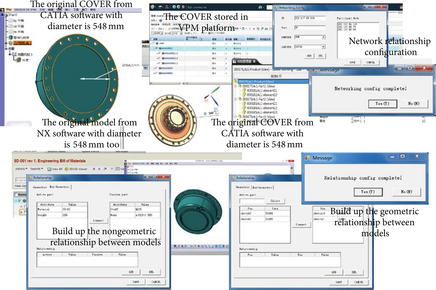
The relationship configuration process between COVER and THIMBLE.

The process of perception between COVER and THIMBLE.
Another design change instance occurred between the SHAFT and GEAR. The SHAFT is the active part and the GEAR is the passive part that they have assembly relationship. A diameter in SHAFT is increased from 58 mm to 59 mm which is encapsulated into FRO file. The FRO file is broadcasted to the VPM platform. With looking up the MARO file, the relative GEAR part is found out and a modification scheme is sent to the owner of GEAR part. If the designer accepts the modification scheme, the parameter value of GEAR hole is changed to 59 mm immediately. The relationship configuration process between SHAFT and GEAR is shown in Figure 11. The process of perception between them is shown in Figure 12.

The relationship configuration process between SHAFT and GEAR.
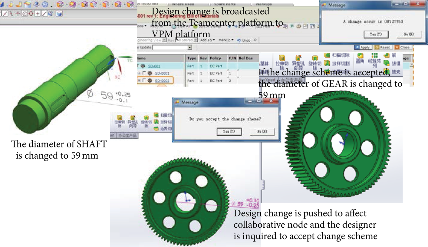
The process of perception between SHAFT and GEAR.
We can find that the change on design model is captured automatically and then transferred to affected collaborative node while irrelevant node will not receive any of it. In the meantime, the affected design model will be found out from data management platform automatically. Moreover, the possible change will be reasoned out according to received change contents and express on selected model. When designer opens the workspace, he can find a change affecting his own design model and then open the affected design model to get possible change scheme directly. As a matter of fact the design change message can take effect, by judging workspace status of designer, asynchronously or synchronously according to collaborative design requirement.
6. Conclusions
This paper aims to build collaborative perception ability directly between the models distributed on the network. A new “model to model” perception mode is proposed which maintains the design coherence between different design platforms. To broadcast the design change in distributed environment, a set of perception ontology descriptions are built up. The PRO is built to describe the relationship between distributed design models; The FRO is built to describe the relationship between features of design models; MARO is built to keep the coherence of the correlation after design change.
A “model to model” perception process is divided into four phases. In change capturing phase, the changed geometric features or nongeometric attribute can be recognized by design change searching method. In design change broadcasting phase, the influenced design models are discovered automatically by change broadcasting method. The coherence of design models is maintained by change self-adapting method in collaborative self-adaption phase.
Through the application of “model to model” perception methodology, complex product collaborative design capability is enhanced. The advantages are concluded as follows. Firstly, the design model is not only the carrier of design result but also the smart model that can broadcast or receive the design change automatically. Secondly, the obstacles of different model format, because of the difference among the digital platforms, are eliminated that make the design change broadcast freely in distributed networking. Thirdly, the design change scheme corresponding to change on relative model is pushed to designer instead of finding out hardly by designer.
Footnotes
Appendix
See Table 5.
Conflict of Interests
The authors declare that there is no conflict of interests regarding the publication of this paper.
Acknowledgments
The project was supported by the Natural Science Basic Research Plan in Shaanxi Province of China (2012JQ7002) and the National Natural Science Foundation of China (51205320).