
Abstract
In order to design antirotation wire rope, while considering the control of the axial strain and flexibility, the requirements that make the wire rope antirotation while making the axial strain little and flexibility excellent were presented. The relationship between axial force and twisting moment of wire rope with axial and rotational strain was given according to the linear stiffness coefficient. It was concluded that the twisting moment and axial strain under tensile load only depend on wire rope's geometry parameters which consist of helical angle and wire diameter. And the expression of bending stiffness was given. Through the analysis of an example, we find that the outer strand has a stronger effect on the tensile, torsional, and bending stiffness. And the closer the strand's helical angle is to 90°, the bigger the tensile stiffness and the bending stiffness are. The helical angles that give consideration to all the three stiffness coefficients can be found. These can be used for reference when designing antirotation wire rope.
1. Introduction
Wire rope was widely used in the field of mine hoist system, crane, transport machinery, and so on due to its advantages of excellent flexibility and high tensile strength. Wire rope will generate a rotary motion or twisting moment when subjected to tensile load because of its special helical structure, and the tensile and bending stiffness vary with the change of twisting parameters. But we require the wire rope antirotation and axial elongation being not too big and the flexibility being excellent on occasion of mine hoist, crane lifting, and so forth. Some researches have been done into helical-structure rope [1–4]. The physical model and force conditions of antirotation wire rope were studied by some scholars [5–8]. The axial and torsion strain of wire ropes and a single strand under axial tensile load were studied by some researchers [9–13]. The flexibility and bending stiffness of strand were also studied by some scholars [14–16]. The linear stiffness coefficients of wire rope were deduced by Cao [4]. But only one parameter was considered when antirotation wire ropes were designed. There is little research on calculation for design of antirotation wire rope, and no researches were done to colligate these three parameters. The bending, torsion, and Poisson's effect of wire rope were ignored in traditional design of antirotation wire rope; therefore, the result was not precise. And the effect of design parameters on tensile and bending stiffness was not considered.
Therefore, coupling parameters were put forward, which consist of antirotation, tensile characteristics, and flexibility. After studying the relationship between twisting moment and axial strain with stiffness coefficient, the difficulty of solving the nonlinear equations was solved based on the linear stiffness coefficient that ignored the extrusion deformation of fiber-core. The bending stiffness of wire rope was also given. Wire rope could be designed conveniently using tensile, torsional, and bending stiffness coefficient. At last, the effect of helical angles for different layer on three stiffness coefficients was obtained. Wire ropes can be designed according to the conclusions.
2. Requirement of Antirotation and Little Axial Strain and Excellent Flexibility
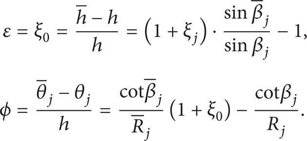
Tensile and torsional movements will affect each other when external axial load is applied because of the helical structure of wire rope (as in Figure 1(a)); therefore, the relationship between force and strain can be formulated according to [2, 17]

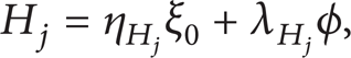
where T and Mdenote tensile force and twisting moment, ε and ϕ denote the axial strain and angle of twist per unit length, Q1 denotes tensile stiffness coefficient, Q2 and Q3 denote the interaction coefficient of tensile and torsional motion, and Q4 denotes torsional stiffness coefficient.

The structure of wire rope 36 × 7 + FC.
In order to make wire rope antirotation under axial load, as long as make sure that twisting moment M do not vary with the change of axial strain ε. Only let
Wire rope has excellent flexibility which means that the radius of curvature can be very small subject to a small bending moment. The relationship between them can be formulated as
3. Stiffness of Wire Rope
3.1. Linear Tensile and Torsional Stiffness
Figure 1(b) is the sectional view of wire rope; Figure 1(c) is the stretch-out view of strand centerline before and after deformation. In Figure 1(c), lj, R
j
, β
j
, and θ
j
denote the length, helical radius, helical angle, and angle swept out by helical strand, respectively, of the strand in jth layer, and h denotes the length of wire rope. ξ0 is axial strain of wire rope and of the fiber-core; ξ
j
, Δβ
j
, ΔR
j
, and ϕ
j
are axial strain, increment of helical angle, reduction of helical radius, and angle of twist per unit length, respectively, of the strand in jth layer. “
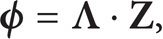
According to [2, 4], the axial strain ε and angle of twist per unit length ϕ of wire rope can be written as
By using Taylor Formula


The reduction of helical radius of strand in jth layer can be formulated as

where the coefficients QΔRa_jk and QΔRb_jk are given in Appendix (A.1).
By virtue of (3), Δβ j can be expressed as

Angle of twist per unit length of strand inside wire rope under external load should be expressed by the change of torsion τ
j
as

where τ aj and τ bj are given in Appendix (A.5).
After substituting (5) and (6) into (7), we have

where coefficients of Qϕa_jk and Qϕb_jk are given in Appendix (A.6).
Equation (8) can then be written in terms of matrix equation:
where
Using (5) and (9), ΔR j can be expressed as follows:
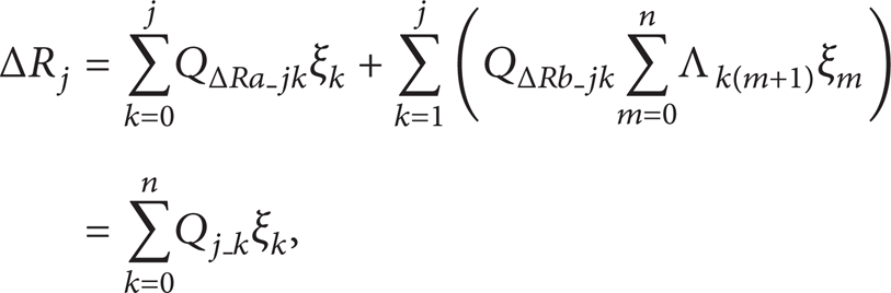
where Qj_k is given in Appendix (A.8).
Combine (3), (4), and (10); the axial strain, variation of helical angle, and variation of helical radius for the strand in jth layer can be linearly expressed by axial strain and twist angle per unit length of wire rope as


where the coefficients of η j , λ j , ηΔβ j , λΔβ j , ηΔR j , and λΔR j are given in Appendix (A.11)–(A.14).
The axial force and twisting moment of strand in jth layer could be formulated as T
j
= E
j
A
j
ξ
j
,

where coefficients of η T j , λ T j , η H j , and λ H j are given in Appendix (A.15).
The bending moment of strand can be expressed by the variance of curvature κ
j
as

where η G j and λ G j are given in Appendix (A.16).
According to [2, 18], the shearing force of helical strand could be written as

where η N j and λ N j are given in Appendix (A.17).
According to [2, 4, 17], the total axial force and axial twisting moment can then be written as

where E f is Young's modulus for fiber-core, A0 is sectional area of fiber-core, and mj is the quantity of strands in jth layer.
Substitute ((14))–((17)) into (18), and by virtue of (1), Q1 and Q3 could be formulated as

It should be stressed that tensile and torsional stiffness coefficients are constants for a given wire rope and are dependent on the rope geometry parameters and wire material properties only. The diameters of rope and wire are usually determined by the axial load that they have to bear. Therefore, we can do a little on diameter of wire to improve the performance of wire rope. The helical angle of strands and wires inside strands can be optimized to adapt to the special conditions.
3.2. Bending Stiffness
A strand inside wire rope can be regarded as a multiple helical spring; its bending stiffness can be defined by the following equation according to [2, 19, 20]:

The bending stiffness of fiber-core can be written as

For a rope, the bending stiffness could be approximated by the bending stiffness of fiber-core and each strand in the rope because the friction has a small influence on it according to [2, 20]. So the bending stiffness of wire rope can be written as

where the term ν
j
cos2β
j
has much smaller effect and with negligible error ν
j
may be set equal to Poisson's ratio of wire material ν. The Young modulus for strand in jth layer can be written as

4. Verification of Linear Stiffness Coefficient
4.1. Parameters
The 36 × 7 + FC wire rope is chosen, in which there is a fiber-core surrounded by thirty-six seven-wire strands. The innermost layer will be called strand 1; the middle and the outmost layer will be called strand 2 and strand 3, respectively. It is assuming that every strand is absolutely the same. The parameters are as follows: the diameter of fiber-core is 4.6 mm, the diameter of center wire inside strands is 1.316 mm, the diameter of outside wire inside strands is 1.25 mm, and the helical angle of wire inside strands is 75°. Young's modulus and Poisson's ratio of steel wire are 2 × 10¹¹ Pa and 0.3, respectively, while those of fiber-core are 3 × 10¹⁰ Pa and 0.4.
4.2. Result Analysis
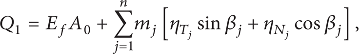
The twisting moment could be solved by using both linear stiffness coefficient and simultaneous nonlinear equations, in case of rotational movements of two ends which are restricted and the value of axial strain is known. The twisting moment of wire rope under axial strain ε = 1.5 × 10⁻³ is depicted in Figures 2, 3, and 4; Figure 5 is the twisting moment of wire rope with axial strain ε varying from 1.0 × 10⁻³ to 2.0 × 10⁻³ when β1 = 75°, β2 = 75°, and β3 = 105°.

Twisting moment with β1 varying.

Twisting moment with β2 varying.

Twisting moment with β3 varying.
Twisting moment with ε varying.
According to Figures 2–5, the result of twist moment under external load that is obtained by linear and nonlinear method is basically the same, which proves the correctness of linear stiffness coefficient. Therefore, we can design antitwist wire rope using the linear stiffness coefficient in (19) and (20).
By virtue of Figures 2–4, twisting moment has both positive and negative value; the reason is as follows. The twisting moment generated by strand 1 and strand 2 whose helical angles is below 90° is positive, while that generated by strand 3 is negative. Twisting moment is zero when moment of strand 1 and strand 2 is neutralized by that of strand 3. So there will be positive and negative twisting moment when the helical angles change.
5. Example Analysis
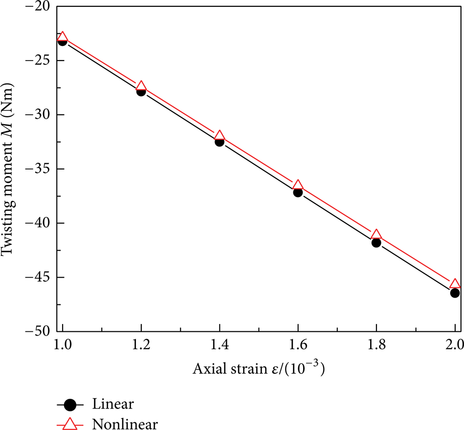
The parameters in Section 4.1 were used. In order to make twisting moment of all strands could cancel out each other, innermost layer and middle layer are Lang lay, and outermost layer is regular lay. Since the expression of Q3 is very complex, solving another helical angle through Q3 = 0 with two helical angles being known is very difficult. But it is convenient to solve the value of Q3 when all helical angles are known. So we can draw the curve of Q3 while two helical are fixed and another varies within a certain range. The curve will contain the point that makes Q3 = 0. So the value of β1, β2, and β3 that make wire rope antirotation could be found. The curves are depicted in Figures 6, 7, and 8.

The curves of Q3 and Q1 with β1 varying when β2 = 73° and β3 = 101°.
The curves of Q3 and Q1 with β2 varying when β1 = 72° and β3 = 101.5°.

The curves of Q3 and Q1 with β3 varying when β1 = 72° and β2 = 70°.
We can get three groups of helical angles that make wire rope antirotation according to Figures 6–8: β1 = 74.5°, β2 = 73°, β3 = 101°; β1 = 72°, β2 = 71.92°, β3 = 101.5°; β1 = 72°, β2 = 70°, and β3 = 102.008°. And a lot of combinations will be obtained by changing the fixed angles. In addition, the closer the strands’ helical angle is to 90°, the larger the tensile stiffness Q1 is; outer strands have stronger influence on Q3 and Q1 by observing the slope of curves.
The curves of bending stiffness with the helical angles varying are depicted in Figure 9, according to (24).

Bending stiffness with helical angle varying.
According to Figure 9, the closer the strands’ helical angle is to 90°, the larger the bending stiffness is, that is, the worse the wire rope's flexibility is. In addition, the curves are symmetrical about β = 90°. The outer strands have a stronger influence on bending stiffness according to the slope of curves.
Above all, when wire rope is designed, the tensile stiffness and torsional stiffness cannot reach the best at the same time while meeting the requirement of antirotation, so we should consider the actual working conditions to know how to choose the structure parameters reasonably.
6. Conclusion
The requirements that make the wire rope antirotation while with good performance in resisting axial elongation and excellent flexibility were given according to the force conditions of helical structure. The stiffness coefficients play the major role; the value of stiffness coefficients only depends on helical angle of every layer when the structure of wire rope and the radius of wire are known.
The difficulty of solving the nonlinear equations is solved by using the expressions of linear stiffness coefficient. We can get the helical angle of layers that make wire rope antirotation conveniently by making the curves of Q3 and β. And its correctness was verified by comparing with the result of nonlinear calculation. So the linear stiffness coefficient can be used as theoretical basis of designing antirotation wire rope.
For the tensile and bending stiffness, when the helical angles approach 90 degrees, the response of stiffness to helical angles gets slower.
The outer layer has a stronger influence on stiffness than inner layers. The torsional, tensile, and bending stiffness can be regulated by slightly adjusting the helical angle of outer layer. These can be regarded as the theoretical basis of adjusting the structure parameters.
The tensile properties and flexibility of wire rope cannot reach the best at the same time. Therefore, appropriate value of helical angle should be chosen according to the needs of working conditions.
Footnotes
Appendix
The coefficient that is in expression of twisting radius variation ΔR j is as follows:
where ηΔr k and λΔr k are coefficients which depend on the geometric parameter of strand and Poisson's ratio for wire material only.
According to [2], the curvature of strand can be formulated as
By using Taylor Formula
According to [2], the torsion of strand can be formulated as
By using Taylor Formula
The twist angle per unit length of strand in jth layer can be given as
The matrix of
The reduction of helical radius ΔR
j
is written as
When j varies from 1 to n,
Convert the n equations into matrix form,
where,
Substitute (11) into (3); the increment of helical angle for strand in jth layer is linearly written as Δβ j = ηΔβ j ξ0 + λΔβ j ϕ, where
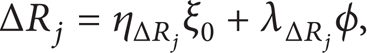
Substitute (11) into (10); the reduction of helical radius for strand in jth layer is linearly written as ΔR j = ηΔR j ξ0 + λΔR j ϕ, where
The axial force and twisting moment of strand in jth layer could be formulated as T j = Qj1ξ j + Qj2ϕ j and H j = Qj3ε j + Qj4ϕ j . According to [4, 17], substitute the expression of ε j and ϕ j in (11) and (7) into it, having T j = η T j ξ0 + λ T j ϕ and H j = η H j ξ0 + λ H j ϕ, where
Conflict of Interests
The authors declare that there is no conflict of interests regarding the publication of this paper.
Acknowledgments
This research is supported by “National Science Foundation for Young Scientists of China” (Grant no. 51005233), “National Key Basic Research Program of China (973 Program)” (Grant no. 2014CB049401), “Program for New Century Excellent Talents in University” (NCET-13-1017), “Program for Innovative Research Team in University” (IRT1292), and “a Project Funded by the Priority Academic Program Development of Jiangsu Higher Education Institutions ‘PAPD'.”