
Abstract
An adaptive terminal sliding mode control for six-degree-of-freedom electromagnetic spacecraft formation flying (EMFF) in near-Earth orbits is presented. By using terminal sliding mode (TSM) technique, the output tracking error can converge to zero in finite time, and strong robustness with respect to disturbance forces can be guaranteed. Based on a rotated frame F r and the adaptive TSM controller, the special magnetic moment of the steerable magnetic dipole is computed. The angular momentum management strategy (AMM) is implemented in a periodically switching fashion, by which the angular momentum buildup was limited. Illustrative simulations of EMFF are conducted to verify the effectiveness of the proposed controller.
1. Introduction
Spacecraft formation flying (SFF) represents the concept of distributing the functionality of large spacecraft among smaller, less-expensive, cooperative spacecraft [1, 2]. Specifically, NASA and the U.S. Air Force have identified spacecraft formation flying as an enabling technology for future missions. The practical implementation of the SFF concept relies on the accurate control of the relative positions and orientations between the participating spacecraft for formation configuration. The conventional thruster-based schemes may require continuous expenditure of fuel to maintain formation geometry that can contaminate the sensitive sensors on board and mission lifetime also becomes dependent on the fuel available [3, 4].
To alleviate these concerns, several propellant-free formation flying methods have been proposed in the literature. The propulsive conducting tethers and spin-stabilized tether systems have been proposed in place of on-board propulsion systems to form and maintain satellite formations [5, 6]. King et al. [7] have presented Coulomb force approaches to maintain a formation. The flux pinning technology has been applied to achieve passively stable configurations by HTS electromagnetics [8]. LaPointe [9] has presented the microwave scattering formation flight method. Radiation forces on the order of 10-9 N/W may be generated using electromagnetic gradient forces or scattering forces; microwave beam powers of 10 kW can thus produce restoring forces of approximately 10 μN, which are sufficient to correct a number of orbital perturbations. Miller et al. [10, 11] address the novel concept of electromagnetic formation flying (EMFF) in which high temperature superconducting (HTS) wire technology is used to create magnetic dipoles on each spacecraft that can be used to maintain and reconfigure the spacecraft formation. However, Since magnetic force on each spacecraft in the formation can be applied in any arbitrary direction which can be easily created by steerable magnetic dipoles, EMFF has advantages in terms of controllability [4].
A critical component of EMFF is an effective formation flying control. The dynamics and control problem associated with EMFF become highly challenging, due to the nonlinear nature of the magnetic forces. Ahsun and Miller [3] have presented a hybrid adaptive control scheme in which translation control is implemented in a centralized fashion with a decentralized attitude control. Elias et al. [12] designed a linear optimal controller based on the linearized dynamics. Kong et al. [13] addressed the use of electromagnetic dipoles for relative position and orientation maintenance as needed for the terrestrial planet finder (TPF). Reference [14] derived the dynamics of an N-spacecraft EMFF (in 2D) for deep space missions and discussed a nonlinear control law using potential functions.
The orientation of a dipole obviously depends on the orientation of the body axes in the inertial space, and changing the dipole on one spacecraft affects actuation on all other spacecraft in EMFF. Therefore, general asymptotical stability may not deliver fast enough convergence to meet EMFF control for high-precision situation. The recently developed terminal sliding mode (TSM) control enables convergence to the desired state in finite time [15–18]. This technique has been used successfully in some control designs, such as robotic manipulators [17] and mobile target tracking [18]. The physical interpretation of finite time convergence lies in the fact that the convergence rate of TSM grows exponentially when the state is near equilibrium.
In this Paper, we confine our attention to adaptive TSMC design for EMFF in near-Earth orbits. The remainder of this paper is organized as follows. Section 2 presents a detailed 6-DOF dynamic modeling for EMFF in near-Earth orbits. In Section 3, a position/attitude tracking controller based on TSM is developed for EMFF, which ensures error convergence in finite time and strong robustness of the bounded disturbances. Based on a rotated frame F r and the adaptive TSM controller, the special magnetic moments of the Steerable Magnetic Dipole (SMD) are computed. The AMM strategy is implemented in a periodically switching fashion. Simulation results are presented in Section 4. Finally, Section 5 concludes this paper.
2. System Model
Spacecraft formation constitutes an N-body mechanics problem. Figure 1 shows a typical formation system including N spacecrafts orbiting a central body (Earth). The spacecraft 0's designated as the “leader” spacecraft. We make the following considerations. (1) The ECI frame F
I
is defined with its origin at the center of Earth, its X-axis points toward vernal equinox, Z-axis points toward celestial north pole, and Y-axis completes a right-handed axis system. (2) The Hill frame F
H
is used to visualize the relative motion of each follower spacecraft with respect to the leader spacecraft. The x-axis aligned in the radial (zenith) direction, the z-axis is perpendicular to the orbital plane and points in the direction of the angular momentum vector, and the y-axis completes the right-hand system. (3) The orbital frame F
Oi
is used in the attitude control. The reference frame is rotating about the y-axis with respect to ECI frame at orbital rate. The roll axis x is in the fight direction, the pitch axis y is perpendicular to the orbital plane, and the yaw axis z points toward the Earth. (4) A body frame F
Bi
attached to the body of ith spacecraft with the center of mass of the spacecraft is also defined to describe the orientation of each spacecraft in the inertial space. (5)
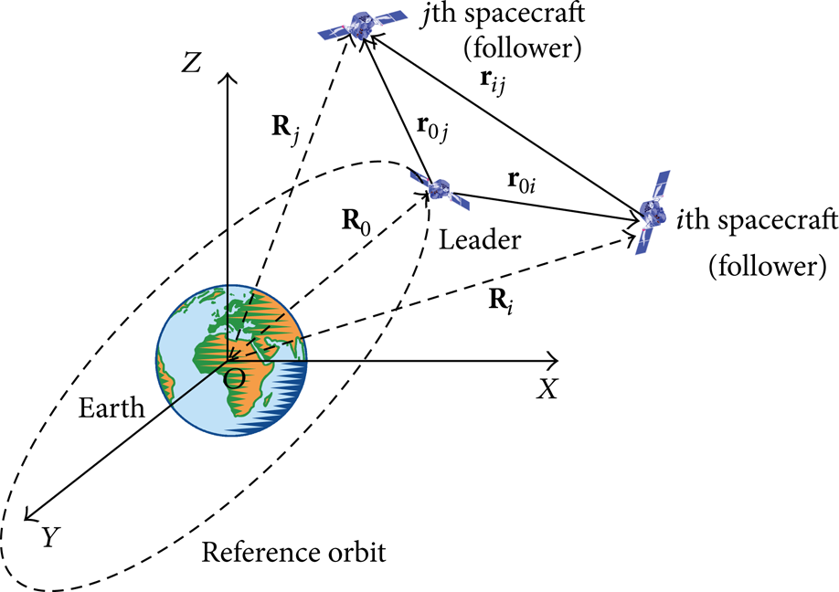
Schematic representation of the EMFF system.
2.1. Translational Dynamics
Designating spacecraft 0 as the leader of the formation, the relative dynamics of ith spacecraft in the Hill reference frame F H can be represented as

where ω
O
is the orbital angular velocity of the leader.

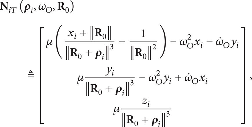
where μ is gravitational constant of earth.
Note that

where

By approximating the coils on each spacecraft to SMD, the magnetic field due to the jth spacecraft can be written as [3, 10]

and the force between spacecrafts can be written as

where μ0 = 4π × 10−7 T·m/A is the permeability constant.
2.2. Attitude Dynamics
To avoid singular points, the Euler parameter is chosen to describe the attitude of the spacecraft. Let
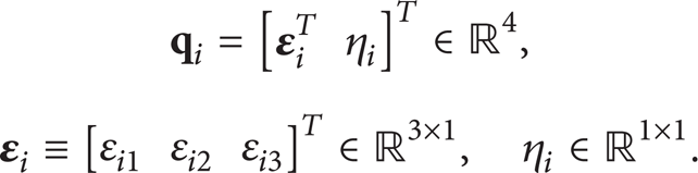
The Euler parameters, which are equivalent to the coefficients of unit quaternion, have unit norm by definition; hence

Attitude kinematics and dynamics of the spacecraft are governed by [19]


where
where


A very important factor presented in the disturbance torque term is the torque that acts on the spacecraft due to the Earth's magnetic field. This torque can be written as [4]

where
Substituting (10) into (11), the attitude dynamics can be written compactly as

where

2.3. Combined Attitude and Translational Dynamics
Combining the attitude dynamics in (1) and the translational dynamics in (16), the following 6-DOF dynamics equation for formation flying is obtained:

where

3. Adaptive Terminal Sliding Mode Control Design
In this section, an adaptive terminal sliding mode controller is designed for the follower spacecraft based on the dynamic model in (18) and the TSM technique. With this controller, the follower spacecraft can track the desired attitude and relative position trajectories simultaneously.
3.1. Error Dynamics Equation
The trajectory tracking errors of the follower spacecraft are defined as
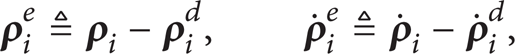
where

where
The error Euler parameter is chosen to describe the attitude error of the spacecraft with respect to the reference attitude. The error Euler parameter is determined as follow [19]:

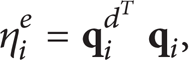
where
Differentiating (22) with respect to time and utilizing (10), the attitude kinematics equations with error Euler parameter are given by

where
Differentiating (24), one can obtain that

where

Substituting (24) and (25) into (11), the error attitude dynamics are derived as follows [19]:

where
Let

where

3.2. Controller Design
The terminal switching planes can be describe as [16–18]
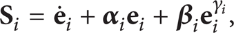
where

where ϑ ni is the adaptive gain.
Utilizing (28), (30), and (31), an adaptive terminal sliding mode control law is designed as follows:

where

Substituting (32) into (18) produces the closed-loop dynamics

Consider a Lyapunov function as follows:

where
The first derivative of (30) can be expressed as
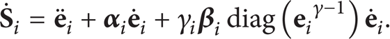
Differentiating (35) and utilizing (36), one can obtain that

where
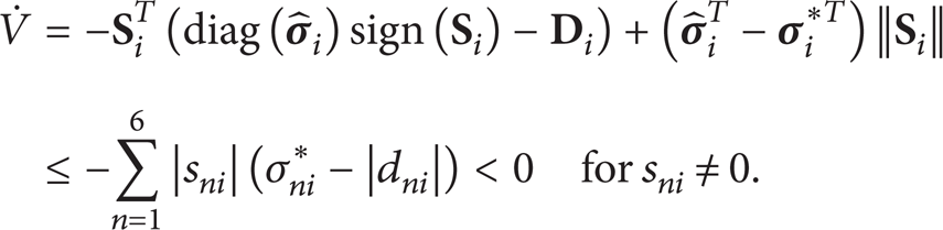
It means that the switching planes s ni (n = 1, 2, …, 6) converge to zero [20]. On the other hand, in the TSM s ni = 0 (n = 1, 2, …, 6), the system state will reach zero in finite time [17].
Remark 1. For the purpose of eliminating chattering, a common practice is to replace the signum function of (32) with a continuous saturation function

where ξ ni >0 is the width of the boundary layer. Equation (32) can be written as
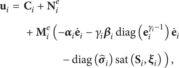
where

Remark 2. There exists a possible singularity in sliding mode controller as

while sliding and that the component in (32)

Consequently there will be a singularity in (32) unless γ i is chosen so that 2γ i >1. To satisfy this requirement we set γ i = 3/5 for the examples to follow.
3.3. Compute the Special Magnetic Moments of SMD
The adaptive sliding mode controller

Substituting (5) and (7) into (44) produces

Note that (7) gives the force on the ith SMD due to the jth SMD and it depends on the distance between the two SMDs and the orientation of both SMDs in the inertial space. It rises to the complexity of the expression for the magnetic. Here, we consider a two-spacecraft electromagnetic formation flying (EMFF) array. By defining a rotated frame F r (see Section 2), a simplified algebraic form of (7) is obtained

Utilizing (45) and (46) produces that
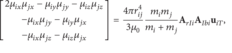
where
Let

The special magnetic moments of SMD can be computed using (48), by which the follower spacecraft can track the desired relative position trajectories.
3.4. Angular Momentum Management
For EMFF in near-Earth orbits, a constant disturbance torque may act on each spacecraft due to the Earth's magnetic field that causes the reaction wheels on each spacecraft to quickly become saturated. In order to avoid this situation, the angular momentum management strategy herein can be utilized, which is based on a unique nonlinearity of the magnetic torques [3, 4]. The force acting between a pair of dipoles depends on the product of the individual dipole values. By switching the polarity of all dipoles in the EMFF, the torque acting on the spacecraft due to Earth's magnetic field changes sign, but the torques and forces due to the other spacecraft in the system do not. As can be seen from (15), it results in a net cancellation of the effect of the Earth's magnetic field on the average sense.
4. Numerical Simulation
The adaptive terminal sliding mode controller equation (40) was simulated for a two-spacecraft formation flying control. Considering the nonlinear dynamics with disturbance
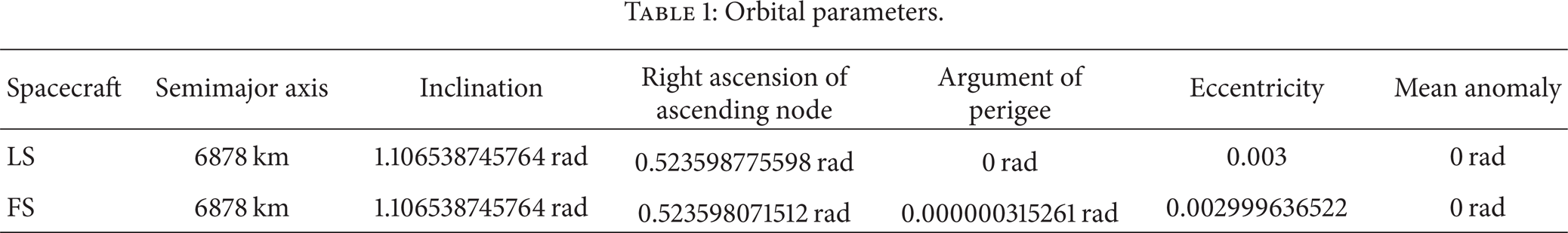
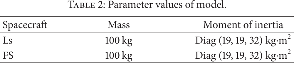
Orbital parameters.
Parameter values of model.
The follower was commanded to move around the leader in an elliptic orbit. The desired trajectory was generated by solving nonlinear equation (1) numerically (set

The relative position/velocity of the follower was initialized to

The parameters of the adaptive sliding mode controller are then

In this simulation, a switching time of 100 second was used for AMM. Figures 2–6 show the simulation results, which are obtained by simulating the adaptive terminal sliding mode controller. The phase portrait of the trajectory

Actual trajectory
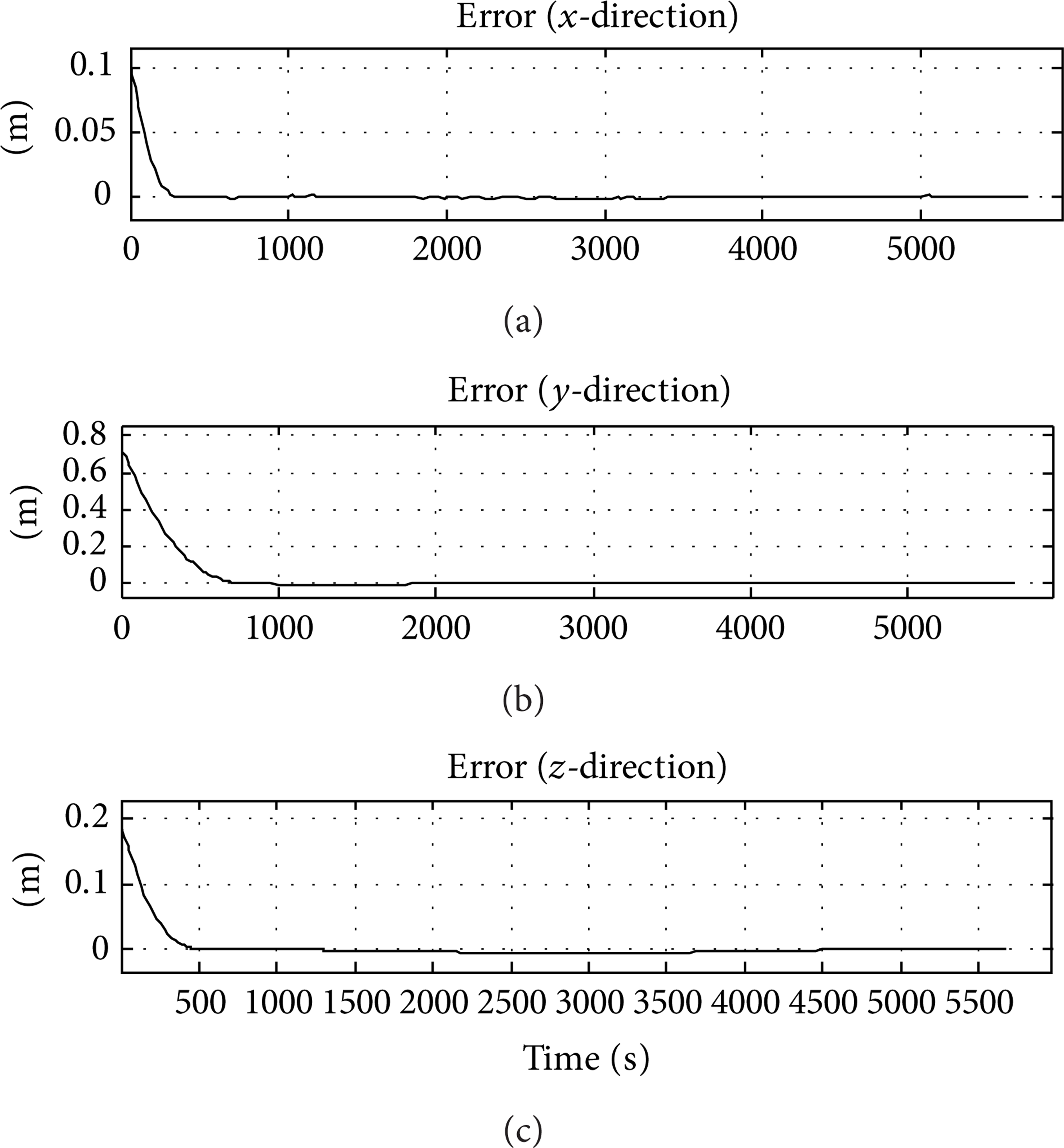
Position tracking error.

Attitude tracking error.
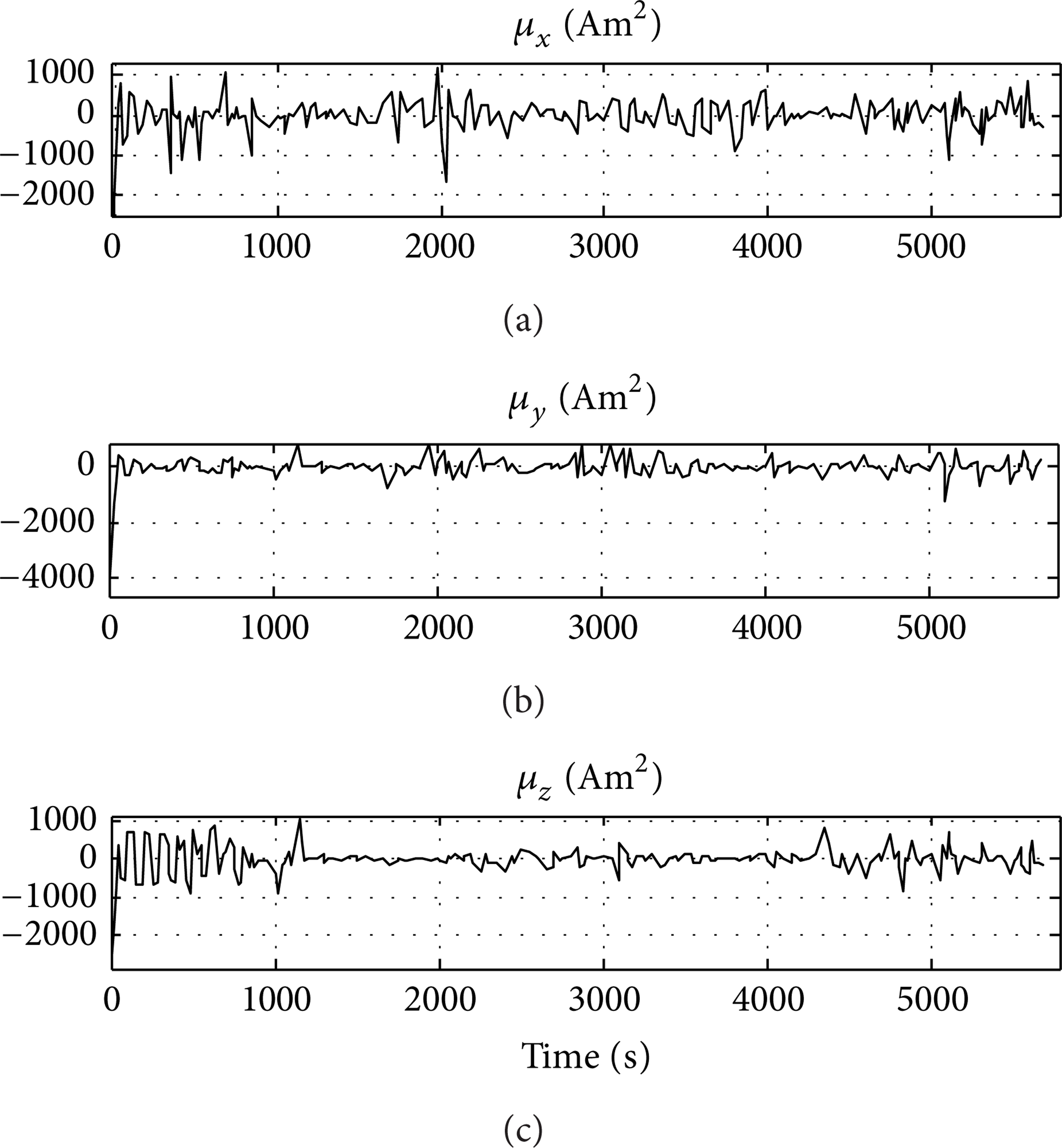
Magnetic dipole strength in FB1 frame.
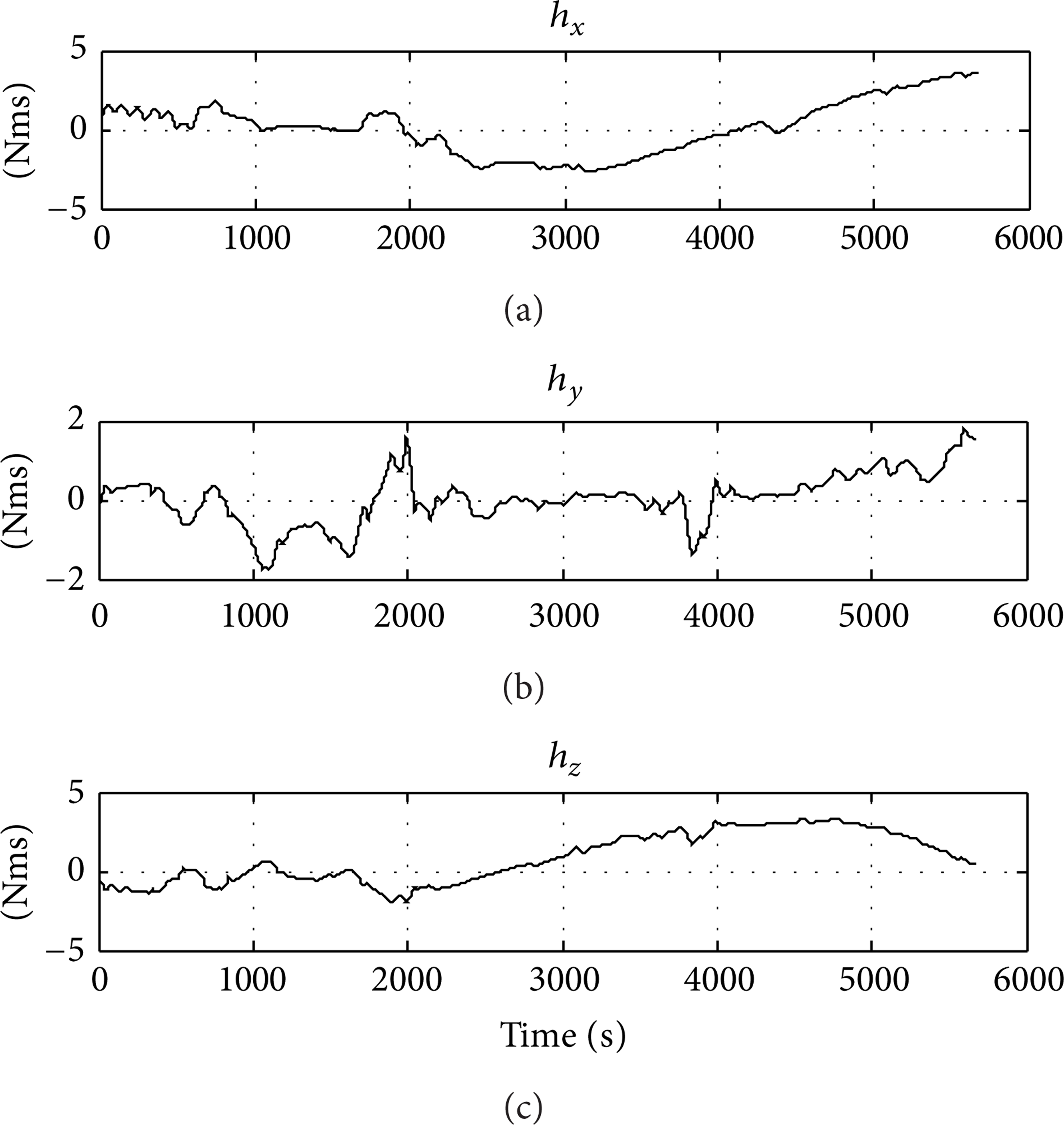
Reaction wheel angular momentum.
5. Conclusions
In this paper, we consider the control problem for six-degree-of-freedom electromagnetic spacecraft formation flying (EMFF) in near-Earth orbits. Firstly, the combined attitude and translational dynamics are presented. Secondly, we confine our attention mainly to the position/attitude tracking control using the terminal sliding mode and adaptive control technique. Based on a rotated frame F
r
and the adaptive TSM controller, the special magnetic moments of SMD are computed. The AMM strategy is implemented in a periodically switching fashion. Through numerical simulation, it is clear that the output tracking error can converge to zero in finite time by using the proposed controller and that the angular momentum buildup was limited by AMM. At the same time, strong robustness with respect to bounded disturbances can be guaranteed (in the simulation, the J2 disturbance, the gravity gradient torques
Footnotes
Nomenclature
Conflict of Interests
The authors declare that there is no conflict of interests regarding the publication of this paper.
Acknowledgment
This work was supported by the Natural Science Foundation of China under Grant Nos. 11372353 and 10902125.