
Abstract
For the design of double-row blades hydraulic retarder involves too many parameters, the solution process of the optimal parameter combination is characterized by the large calculation load, the long calculation time, and the high cost. In this paper, we proposed a multiobjective optimization method to obtain the optimal balanced solution between the braking torque and volume of double-row blades hydraulic retarder. Moreover, we established the surrogate model for objective function with radial basis function (RBF), thus avoiding the time-consuming three-dimensional modeling and fluid simulation. Then, nondominated sorting genetic algorithm-II (NSGA-II) was adopted to obtain the optimal combination solution of design variables. Moreover, the comparison results of computational fluid dynamics (CFD) values of the optimal combination parameters and original design parameters indicated that the multiobjective optimization method based on surrogate model was applicable for the design of double-row blades hydraulic retarder.
1. Introduction
Speed limitation and braking of vehicles are extremely important to driving safety. As an auxiliary braking device, hydraulic retarder is characterized by the large high-speed braking torque, the smooth and comfortable braking process, the good heat dissipation performance, and the constant braking speed and has been widely used. The application of hydraulic retarder allows the engine speed of heavy trucks and buses to be distributed in the economical range, thus reducing energy consumption. Foreign auxiliary braking device of vehicles mainly includes electric eddy current retarder and hydraulic retarder, which, respectively, account for 2% and 98% market shares. With the development of heavy trucks and buses, the market requires the superior hydraulic retarder with the high energy capacity, small size, and fast response. Double-row blades hydraulic retarder can take advantage of the radial space of hydraulic retarder and meet the requirements of large energy capacity and small size. However, fluid filling volume is increased in hydraulic retarder and the dynamic response capability is decreased to some extent. The performance parameters of hydraulic retarder include the number of blades, blade angle, and circulatory circle size, which have corresponding ranges. Different parameter combinations allow different hydraulic retarders with different performances. In general, in addition to the requirements of customers, the optimal performance of the products should be realized in the design of new products [1].
With the development of computer technology, computational fluid dynamics (CFD) is also developed rapidly. CFD techniques were adopted to predict product performance [2], chemical or physical processes [3, 4], and fluid flow process [5, 6]. With CFD techniques, Choi et al. [7] predicted the internal flow of turbine in order to choose the best design and verified the reasonableness of the design through the field test. The application of CFD also indicated that CFD was applicable to predict fluid dynamics of hydraulic components.
In recent years, the multiobjective optimization method [1] has been widely used in engineering design [8–10]. Optimization algorithms have been used in the design of hydraulic components. Kesy and Kadziela [11] had applied genetic algorithms in the optimization of the structure of hydraulic component and analyzed the impacts of the optimization constraints of design variables on optimization results and found that the impacts were significant. Their work provided the theoretical basis for the structural design of hydraulic components. Surrogate model used in multiobjective optimization would simplify the solution [12, 13], accelerate optimization, and reduce the calculation cost. Graciano and Le Roux believed that different surrogate models allowed the high accuracy and applied surrogate models in the design of wastewater network system to calculate the optimization results [14]. Forrester and Keane applied surrogate models in the optimization of spacecraft fuel efficiency and illustrated that the surrogate model method allowed the more precise solution for the global optimization [15]. In multiobjective optimization, sample point selection method, surrogate model construction method, and genetic algorithm selection affect optimal results. J. L. Deutsch and C. V. Deutsch carried out multivariate uniformity extensions for Latin hypercube sampling (LHS) of multivariates and provided the comparison analysis, which indicated that an increase in multidimensional uniformity could significantly improve efficiency and that LHS was effective for large-scale multivariate problems [16]. Roshanian and Ebrahimi applied LHS to select sample values of uncertain variables which follow the normal distribution and optimized the reliability multidisciplinary design for disposable launch vehicle with two-stage solid propellant. The optimization results indicated that the reliability met the expectations [17]. Xing et al. proposed a radial basis function and adopted the method in the design of the depth of the automatic control system of certain mine clearance weapon. Moreover, genetic algorithm was adopted in the calculation and the calculation results were compared with the experimental data. The comparison results indicated that this method allowed satisfactory results [18]. Shi and Reitz studied NSGAII applications under different strategies and indicated that the NSGAII was superior to other commonly used algorithms for engine performance optimization [19, 20].
In summary, the application of multiobjective optimization method in double-row blades hydraulic retarder can save manpower and time. On the basis of the studies of single-row hydraulic retarder, combined with the applications of multiobjective optimization methods in mechanical design and engineering, we proposed the multiobjective optimization method for double-row blades hydraulic retarder based on surrogate model. Under the working conditions of the rotor speed of 2000 r/min and fluid filling rate q = 100%, the design variables included blade angle, the number of stator blades of the internal and external working chambers, and the number of rotor blades of the internal and external working chambers. The objective functions include braking torque and volume of hydraulic retarder. In the paper, we acquired sample points with LHS method [21, 22] to perform modeling and CFD numerical calculation for sample points and obtained corresponding volume and braking torque. At the same time, other sets of sample points were selected with LHS to verify the original sets of sample points. Radial basis function was adopted to establish the surrogate model of objective function. Nondominated sorting genetic algorithm (NSGA-II) [23] was used to solve the multiobjective optimization problem and obtain Pareto optimal solution [24], resulting in the optimal combination of design variables of double-row blades hydraulic retarder. Based on the optimal parameter combination, we simulated hydraulic retarder and performed CFD calculation. Then, we compared the new design with original design of hydraulic retarder. The comparison results indicated that the new design of double-row blades hydraulic retarder showed the improved performance.
2. Structure and Working Principle of Hydraulic Retarder
Hydraulic retarder can be divided into open hydraulic retarder and closed hydraulic retarder. Closed hydraulic retarder can be divided into the closed single-chamber hydraulic retarder and closed dual-chamber hydraulic retarder. Derived from hydraulic coupler, hydraulic retarder has the similar structure and is mainly composed of rotor, stator, the working chamber, the input shaft, housing, and the rapid charge-discharge oil mechanism. As shown in Figure 1, it is mainly composed of rotor, stator, the input shaft, heat exchanger, storage tank, and housing.

Schematic diagram of hydraulic retarder structure.
During the operation of hydraulic retarder, the rotor is driven by the transmission system through input shaft. When rotor blades agitate internal working fluid of hydraulic retarder, mechanical energy is transformed into kinetic energy and pressure energy. When the working fluid impacts the stator in the high speed, the absolute speed of the working fluid at the rotor blade outlet is related to blade angle and speed, whereas the relative speed of the working fluid is related to stator blade angle. The working fluid flows into the circulation channel formed between the rotor blade and the housing. The working fluid from the stator impacts the rotor blades in the high speed. During the interaction between the working fluid and the rotor, the working fluid acted on the stator to generate braking torque. It is well known that most of natural or artificial fluids are unsteady [25]. Internal fluid in hydraulic retarder is also unsteady. Energy losses of direction change, impact, friction, and so forth are transformed into the thermal energy of the working fluid. Therefore, the temperature of the working fluid in the hydraulic retarder rises during the internal circulation process and the generated heat is released through the heat exchanger. The volume of hydraulic retarder is related to the blade numbers and blade angles of rotor and stator. During the design and performance prediction of hydraulic retarder, CFD methods are commonly used.
3. CFD Calculation of Hydraulic Retarder
(1) Mass Conservation Equation. Consider

where
(2) Momentum Equation. Consider

where n is the number of phases,
(3) Solving the Braking Torque. See Figure 2.

The solving method of torque at a specified torque center.
The total torque vector at a specified center (A) is computed by summing the cross products of the pressure and viscous force vectors for each surface with the moment vector.
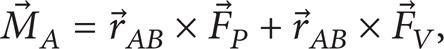
where A is the specified torque center, B is the force origin,
(4) Standard k-∊ Model. Consider

where G k represents the generation of turbulence kinetic energy due to the mean velocity gradients, G b is the generation of turbulence kinetic energy due to buoyancy, Y M represents the contribution of the fluctuating dilatation in compressible turbulence to the overall dissipation rate, turbulence velocity coefficient is μ t = ρGμ(k2/∊), Gμ, C1∊, C2∊, σ k , and σ∊ are the model constants and are, respectively, set to be 0.09, 1.44, 1.92, 1.0, and 1.3.
(5) CFD Calculation of Hydraulic Retarder. As shown in Figure 3, CFD calculation process of hydraulic retarder is generally divided into five steps: three-dimensional modeling, flow extraction, grid division, CFD solution, and postprocessing. Standard k-∊ Model was selected as turbulence model for CFD calculation in the paper. The pressure-based solver was used in the calculation. SIMPLE algorithm was selected as velocity-pressure coupling algorithm. The first-order upwind format was selected as the discrete method. The density of working oil is set to be 860 kg/m3. Dynamic viscosity is set to be 0.0258 N·s/m2. It is assumed that the density and viscosity of working medium do not vary with temperature and that the entire hydraulic retarder is the rigid structure. Therefore, the deformation was not considered in the calculation. The contact surface between rotor and stator was simulated according to the sliding grid method. Inlet boundary condition is set to be the pressure inlet and the outlet boundary is set to be outflow.
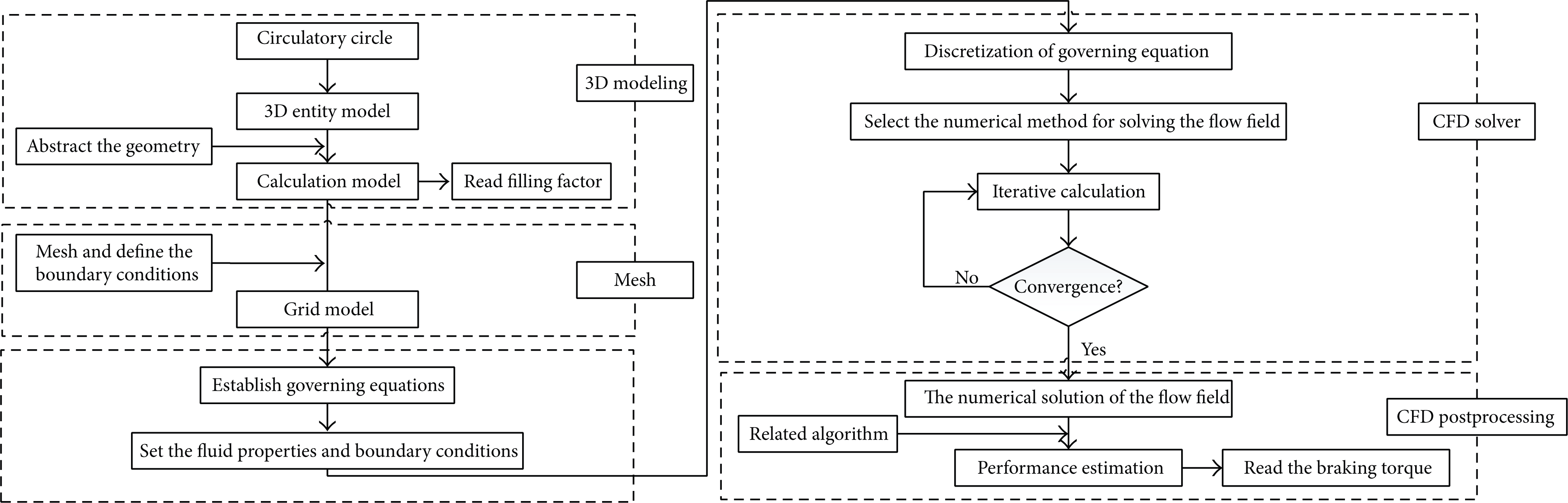
CFD calculation process.
4. Establishment of Surrogate Model
4.1. Design Variables
In the structure parameters of single-row blades hydraulic retarder, blade number, blade angle, and shaft section size have different influences on the braking performance and volume of hydraulic retarder. In the double-row blades hydraulic retarder studied in the paper, blades are the forward blades, circulatory circle is circular, the diameter is 320 mm, the axial width of the flow channel is limited to 56 mm, due to the limitation of the diameter of the input drive shaft, and the sum of the axial sizes of internal and external circular working chambers is 100 mm. The design variable vector is shown as

where x1, x2, x3, x4, x5, and x6 represent the design variables, Znd represents the number of blades of the first working chamber inside stator, Znz represents the number of blades of the small working chamber inside rotor, Zwd represents the number of blades of the large working chamber outside stator, Zwz represents the number of blades of the large working chamber outside rotor, a represents blade angle (°), and dw represents the axial diameter of external working chamber (mm).
According to the ranges of performance parameters of hydraulic retarder [1–3], constraint conditions of design variables were selected as
4.2. The Objective Functions
4.2.1. Braking Torque (T)
Braking torque is the most important performance indicator of hydraulic retarder. Therefore, the braking torque was set as the first objective function in the paper. Through the modeling of sample points, numerical calculation was performed with CFD method to acquire the braking torque values corresponding to sample points.
4.2.2. Volume (V)
Volume (V) directly affects response time of hydraulic retarder. The actual fluid filling process of hydraulic retarder is very complex. In the early fluid filling stage, fluid filling speed is very fast. However, in the later fluid filling stage, fluid filling speed is very slow. The larger volume of hydraulic retarder indicates the longer filling time required for the set filling ratio and the longer response time. Therefore, the volume of hydraulic retarder was set as the second objective function, which was simulated through three-dimensional solid modeling with UG software.
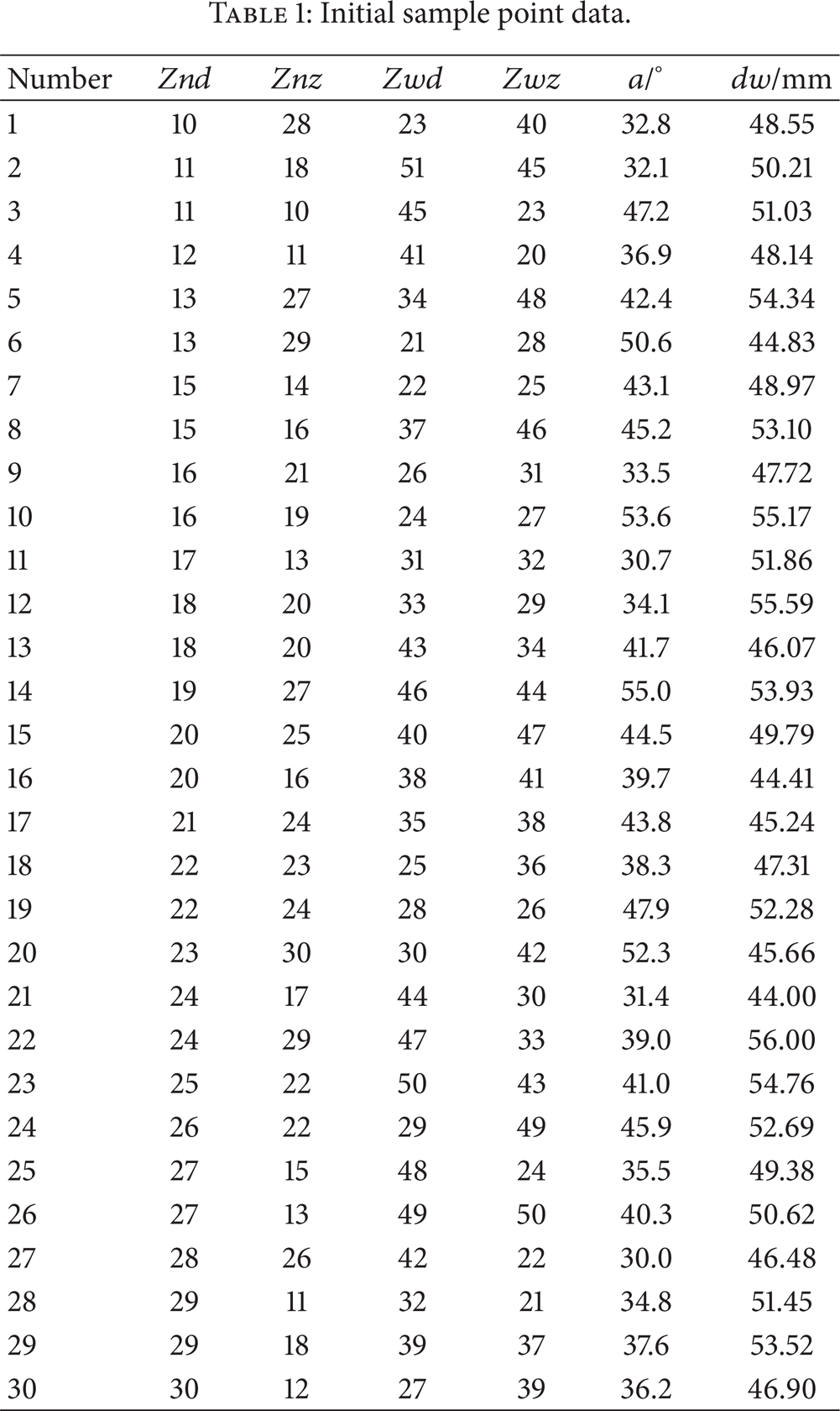
LHS method was used to acquire 30 sets of sample points. LHS method is characterized by an effective space-filling capability and the nonlinear fitting response capability. The initial sample points are shown in Table 1.
Initial sample point data.
Through modeling and CFD calculation, volume values and braking torque values were acquired. According to the relationships between design variables and the objective functions (Figure 4), the design variables show the highly nonlinear relationship with objective functions. The nonlinear relationship was simulated with surrogate model.
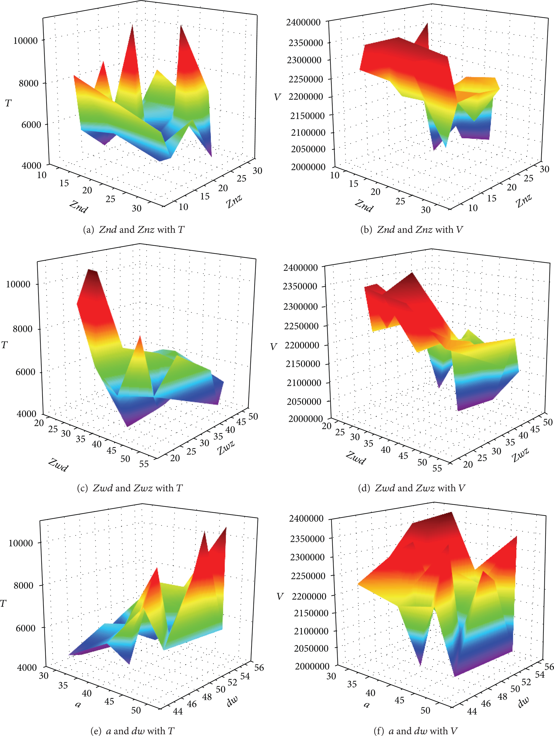
Schematic diagram of the relationship between design variables and objective functions.
4.3. Surrogate Model
Common establishment methods of surrogate models include polynomial response surface methodology [26], radial basis function method [27, 28], and Kriging interpolation method (Kriging Models) [29, 30]. Surrogate models include the interpolation-based surrogate models and regression-based surrogate models, which can express the approximate relationship between design variables and response functions. For the simulation requiring small errors, the interpolation-based surrogate models are more suitable. For the simulation requiring model accuracy and robustness, the interpolation-based surrogate models established with radial basis function are more suitable [31]. Radial basis function allows the satisfactory accuracy within a small amount of tests.
Mathematical model of radial basis function is described as follows: for any basis function, such as

where |

Surrogate model indicates the approximate relationship between the design variables and their response values. Before the application of surrogate models, model precision should be calibrated. In engineering applications, multiple correlation coefficient (R2) is often used to indicate the precision of surrogate model; for the sample data of n sampling points, the sum of squared deviation is denoted as S T ; the regression sum of square is denoted as S R ; the residual sum of squares is denoted as S E ; the multiple correlation coefficient is calculated as

where
R2 is between 0 and 1. The larger value of R2 indicated the higher precision of surrogate model. In engineering applications, if R2 is larger than 0.9, it is believed that the precision of surrogate model is acceptable.
Then, 10 sets of sample points obtained with LHS method were used to detect the precision of 30 sets of sample points. The sample precision detection data are provided in Table 2.
Sample precision detection data.

Error analysis results of surrogate model established with radial basis function are shown in Figures 5 and 6. For the surrogate model of the braking torque, the multiple correlation coefficient, R2, is 0.9612. For the surrogate model of the volume, the multiple correlation coefficient, R2, is 0.9495. The two multiple correlation coefficients indicated that the model met the precision requirements of engineering applications.

Brake torque error (R2 = 0.9612).

Volume error (R2 = 0.9495).
5. Optimization
5.1. Algorithm Selection
During the optimization of performance, shape, and structure of parts or bodies, traditional optimization methods are easy to appear the problem such as local optimal solution. Modern optimization methods can obtain the solution efficiently, avoid the problem of local optimal solution, and be convenient for data transfer with other software. Therefore, modern optimization methods have been rapidly developed in recent years. Multiobjective genetic algorithm, nondominated sorting genetic algorithm-II (NSGA-II), and multiobjective particle swarm optimization are widely used. NSGA-II is modified from nondominated sorting genetic algorithm (NSGA) [32]. Based on the NSGA, the elitist strategy, density estimation strategy, and fast nondominated sorting strategy are introduced into NSGA-II to largely improve the shortcomings of NSGA. NSGA-II shows the good exploration performance and the enhanced Pareto advancing volume.
NSGA-II was used to optimize braking torque and volume according to the parameter settings of NSGA-II shown in Table 3.
The parameter settings of NSGA-II.

5.2. Optimization Results
In the beginning of the optimization, the values of design variables are randomly searched and then substituted into the surrogate models of braking torque and volume for calculation. The calculated results were compared with the set minimum value of braking torque and the set maximum value of volume. The set of calculated results would be discarded if the calculated braking torque or volume was not in the set ranges. The above calculation and comparison were repeated until the global optimal Pareto solution was obtained. At this time, the optimization process was completed. Genetic algorithm was completed after it met the required evolution generations. Then, the optimal values were selected from the calculated results and outputted. Iterative calculation process is shown in Figure 7.

The change of objective functions during the optimization.
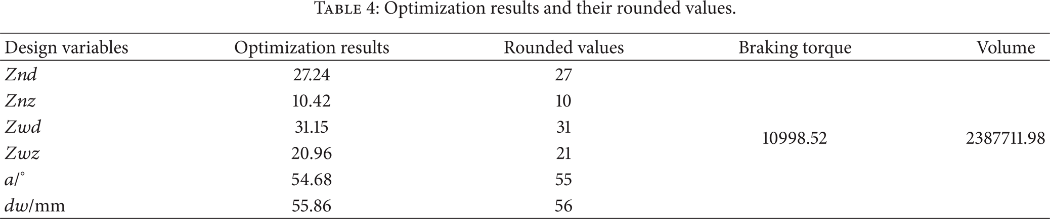
Optimization results and rounded values are provided in Table 4.
Optimization results and their rounded values.
5.3. Comparative Analysis
Three-dimensional model of double-row blades hydraulic retarder was established based on optimization results. Flow channel model was extracted, as shown in Figure 8. Grid model was established, as shown in Figure 9. The grid number was 340,299.

Flow channel model.

Grid model.
By CFD numerical calculation, braking torque (T) and volume (V) were obtained and then compared with response values of surrogate model (Table 5). The errors of braking torque (T) and volume (V) were 4.7% and 4.4%.
Comparison of CFD simulation data and response values of surrogate model.

Table 6 lists the original parameters, braking torque and volume obtained with original parameters, optimized parameters, and braking torque and volume obtained with optimized parameters. After the optimization, the braking torque was improved by 49.7% and the volume was decreased by 2.4%, indicating that braking performance was largely improved and that fast response capability was also increased. Figure 10 shows the comparison results of braking torques of hydraulic retarder under different speeds and full fluid filling state before and after optimization. As shown in Figure 10, the breaking performance under different speeds after optimization was increased dramatically.
Parameter comparison.

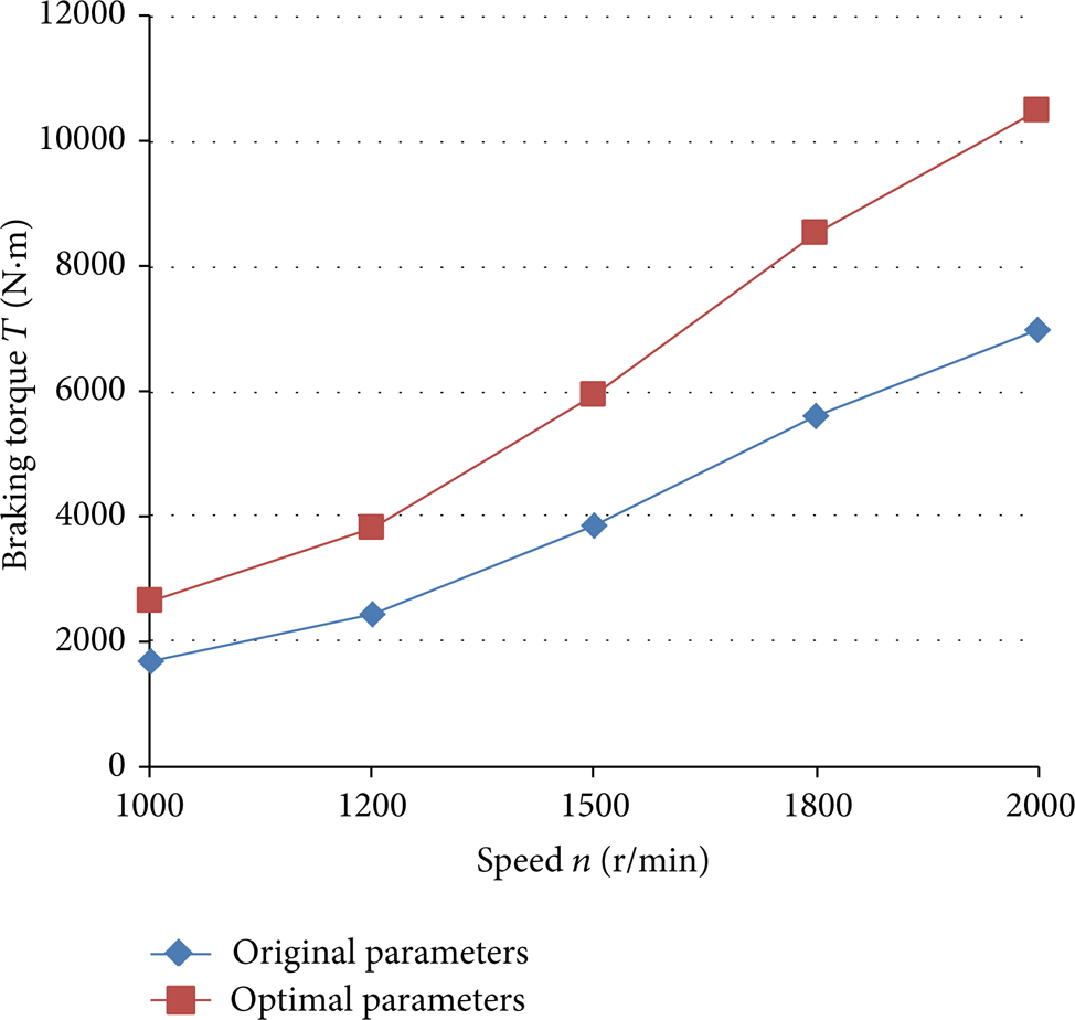
Braking torque comparison under full fluid filling state.
6. Conclusions
Hydraulic retarder has been increasingly widely applied in heavy trucks and buses and has become an important auxiliary braking device. The structure and working principle of hydraulic retarder were introduced in the paper. The calculation principles, methods, and processes of braking torque with CFD were also described. Double-row blade structure can well meet the size requirements of hydraulic retarder. Brake torque and volume are the physical parameters for characterizing the braking performance and fast response performance of hydraulic retarder. In the paper, LHS was used to select 30 sets of sample points firstly and then surrogate models of the objective functions were established with radial basis function. Moreover, the precision of sample points was verified. NSGA-II was used to calculate the optimal solutions of double-row blades hydraulic retarder. We compared the response values of the surrogate model of optimal solution with the values obtained through CFD numerical calculation and found that the deviations between the above two kinds of calculated values were relatively small, indicating that the optimal solution was reasonable. The comparative analysis indicated that multiobjective optimization method based on surrogate model was effective for the design of double-row blades hydraulic retarder.
Conflict of Interests
The authors declare that there is no conflict of interests regarding the publication of this paper.
Footnotes
Acknowledgment
This work was supported by the National Natural Science Foundation of China (Grant no. 51305156).