
Abstract
Study on the influence of rotating stall on the aerodynamic noise of axial fan has important value to warn of the occurrence of stall through monitoring the noise variations. The present work is to analyze the aerodynamic noise before and after the phenomenon of rotating stall by solving Navier-Stokes equations, coupled with the throttle condition and the broadband noise sources model. The impeller exit rotational Mach number and rotational Reynolds number are separately 0.407 and 8.332 × 10⁶. The results show that the aerodynamic noise source of the fan is mainly the rotation noise under the design condition. The vortex noise accounts for the major part of fan noise after the occurrence of stall, and the maximum acoustic power level of the fan appears in the rotor domains. In the evolution process from the stall inception to the stall cell, the high noise regions of the rotor develop along the radial, circumferential, and axial directions, and the area occupied by high noise regions increases from 33% to 46% impeller channels area. On rotating stall condition, the high noise regions occupying about 46% impeller channels area propagate with the stall cell along the circumferential direction at a half of rotor speed.
1. Introduction
Rotating stall, as an unsteady flow phenomenon widely exists in turbo machinery, causes restrictions on the efficiency and operation range of the modern fan or compressor. It is easier for the fan to fall into stall when it works under partial load. Under stall state, the flow field can be destroyed and additional aerodynamic load can be induced, leading to the aerodynamic noise increasing or even fracture of the blades. Therefore, it is important to study the aerodynamic noise before and after rotating stall for the safe operation of the fan.
Research on the flow field of stall process is important to study the influence mechanism of rotating stall on the aerodynamic noise. There are two kinds of widely accepted inception, namely, the modal wave type inception and spike type inception proposed by Camp and Day [1]. Niazi et al. performed the three-dimensional numerical simulation of a high-speed transonic fan rotor considering external disturbance, and the results showed that the reflux first occurred near the blade leading-edge in the rotor tip clearance area [2]. Sano et al. conducted detailed research on the unsteady flow phenomena inside the pump vaned diffuser, such as the rotating stall, the alternate blade stall, and the asymmetric stall [3]. Shen et al. presented a three-dimensional model to study the occurrence of weak rotating waves in vaneless diffusers of centrifugal compressors, and the results showed that the critical flow angle and the stall propagation velocity were affected by the axial distributions of undisturbed flow at the diffuser inlet [4]. Hasmatuchi et al. experimentally investigated the effect of blowing technology on the flow field of a centrifugal pump under rotating stall [5]. Gourdain et al. studied the cyclical fluctuation of the parameters such as pressure and velocity inside the compressor at a stall condition [6]. Lucius and Brenner experimentally studied the speed variation of a centrifugal pump in rotating stall stage [7]. Choi et al. investigated the effects of fan speed on rotating stall inception; the results showed that, at 60% speed, tip leakage flow spillage occurred successively in the trailing blades of the misstaggered blades [8]. Guleren and Pinarbasi investigated the flow effects due to dynamic interaction between the flow leaving the impeller and the volute tongue within the stalled, and the switching between the reverse and jet flows in the diffuser channel was observed under the rotating stall condition [9]. Barrio et al. analyzed the unsteady flow in the near-tongue region in a volute-type centrifugal pump for different operating points [10]. Sheng et al. presented a three-dimensional compressible flow model to study the occurrence of weak rotating waves in unparallel wall vaneless diffusers in centrifugal compressors, and the results showed suppression effects on rotating stall of diffusers with contracting walls and the effects increase with the wall contraction [11].
Aerodynamic noise is mainly caused by vortex and flow separation. So the unsteady behavior of rotating stall may have influence on the aerodynamic noise of the fan. Based on the flow field obtained by the simulation in an axial flow fan, Crosini and Rispoli pointed out that the former curved blade can weaken the secondary flow and control the development of the stall [12]. According to Ouyang et al.'s work, the far-field noise generated by cross-flow fan with different impellers was measured, and it showed the great influence of blade angles on the inflow pattern [13]. Liu et al. investigated the spectrum characteristics of the double rotor in different axial clearance and found the optimal range of the space between the rotors [14]. Argüelles Díaz et al. predicted the far-field noise of a single-stage axial fan by using a new noise prediction method and proved that the method is reliable [15]. Fukano and Jang made a contrast experiment under different flow coefficient and different blade tip clearance in an axial flow fan. The results show that the mutual interference of the blade tip clearance leakage vortex can increase the fan noise [16]. Based on the simulated results in an axial fan with the additional guide vane, Nezym found that angle and height of the guide vane outlet have a significant impact on its flow loss and noise level [17]. Duquette and Visser studied the effect of blade numbers on the aerodynamic characteristics of the fan and found that the fan efficiency gradually increases with the increase of blade number [18]. Scheit et al. analyzed the far-field noise in a centrifugal fan with an acoustic analogy method and presented design guidelines to optimize the radiated noise of the impeller [19]. Carolus et al. investigated two prediction methods for broadband noise of low-pressure axial fans [20]. Neise and Koopmann investigated experimentally a method by which an acoustic resonator can be used to reduce at source the aerodynamic noise generated by turbo machinery [21]. Velarde-Suárez et al. carried out an experimental study about the aerodynamic tonal noise sources in a centrifugal fan with backward curved blades [22]. Filleul made measurements of noise from fans designed for military vehicle cooling installations and two fan rotors in particular have been run under varied test conditions [23]. Morinushi studied the influence of five major geometric parameters on noise and aerodynamic performance of forward curved centrifugal fans [24]. Sutliff et al. conducted an experimental proof of concept test to demonstrate rotor stator interaction tone noise reduction through rotor trailing edge blowing [25]. Li et al. studied that the deviation of installation angle may cause deformation of total pressure and acoustic distribution based on Reynolds time-averaged equation and realizable k-ε turbulent model [26]. Liu et al. investigate the influence of attack angle of compressor cascades on unsteady vortex shedding at trailing edge and the noise radiation, using large eddy simulation model and boundary element method [27]. Li et al., aiming at the aeroacoustics problem of swept axial fan, took the large eddy simulation (LES) and the FW-H method based on the Lighthill sound analogy to simulate the unsteady flow of the fan. Through the fast Fourier transform (FFT) process, the far-field pneumatic noise pressure level distribution of the fan was acquired [28].
Broadband noise source (BNS) models are found to be effective tools in screening turbo machine system with higher noise levels and identifying components or surfaces with high noise generation. It mainly contains Proudman's model for quadrupole source and Curle's boundary layer model for dipole source. In 1952, immediately after Lighthill's acoustics theory, Proudman using Lighthill's theory considered noise generated by a homogenous isotropic turbulence [29]. Using statistical models he derived the analytical expression for the acoustic power (AP) per unit volume. Later Lilley reexamined Proudman's expression and added a correction for time correlation effects previously neglected by Lilley [30]. Sarkar and Hussaini computed numerically radiated acoustic noise using direct numerical simulation (DNS) and found results that are in agreement with Proudman's analytical expression [31]. The boundary layer model is based on Curle's integral where the radiated acoustic pressure was derived as a function of the fluctuating surface pressure of the rigid body surface [32]. The model assumes low Mach number and only accounts for dipole contribution of the source noise. The surface acoustic power (SAP) radiated from the body surface can be computed by this model. Leclercq and Symes compared experimental work and numerical implementation of Curle's integral of bluff bodies in fluctuating flow field [33]. Khondge et al. applied BNS models to predict aeroacoustics performance of a duct and found that predicted noise was directionally supported by experimental data [34].
The present work focuses on two aspects: numerical simulation of rotating stall in an axial fan with software of Fluent [35] and discussion of the aerodynamic noise sources before and after the occurrence of stall. In the first part, the rotating stall phenomenon of the fan is numerically simulated to calculate the unsteady flow field by solving Navier-Stokes equations, coupled with the throttle condition. The aerodynamic performance of the rotor under stall conditions is investigated as well. In the second part, the paper firstly analyzes the variation of maximum acoustic power level in different domains of the fan before and after the occurrence of the stall. Then, based on the broadband noise sources model and the flow field obtained in the first part, the acoustic power level during evolution process of stall inception and the circumferential propagation of stall cell are discussed.
2. Axial Fan Description
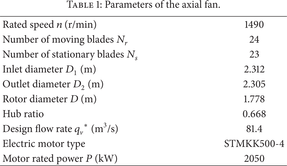
A two-stage variable pitch axial fan, widely used in power plants, is taken as the research object in this paper. There are six main parts of the fan, namely, the inlet collector, the first rotor, the first stator, the second rotor, the second stator, and the outlet diffuser. The three-dimensional geometric model of the axial fan is established by software of GAMBIT as shown in Figure 1. The first and second rotors are marked as rotor 1 and rotor 2, and the stators are marked as stator 1 and stator 2 as well. The detailed fan parameters are shown in Table 1.
Parameters of the axial fan.
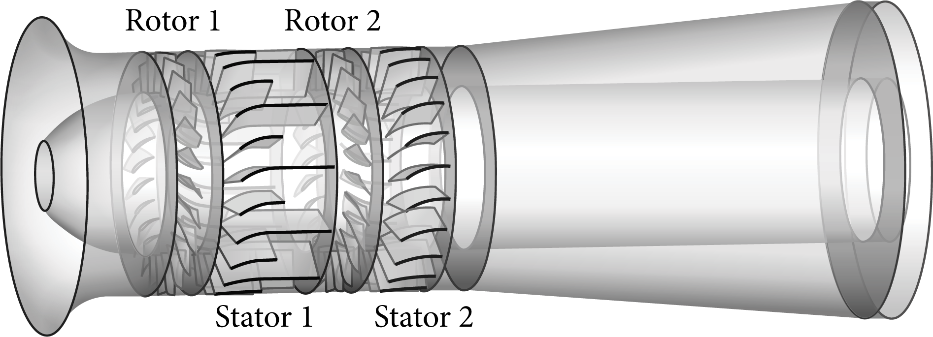
Geometrical model of the axial fan.
3. Numerical Simulation
3.1. Governing Equations
The phenomenon of rotating stall in an axial fan is considered an unsteady flow, and the temperature and density are constant. The unsteady Reynolds averaged Navier-Stokes equations (URANS) are used to describe its flowing law, coupled with the realizable k-ε turbulent model which is suitable for solving rotating flow, secondary flow, and separation flow problems. The pressure-velocity coupling algorithm and second-order upwind discretization scheme are adopted in the numerical simulation.
3.2. Meshing Strategy
The meshing strategy is based on multiblock grid technology. The rotors and stators are meshed with tetrahedral unstructured grids due to its better applicability, while the other sections are meshed with hexahedral structured grids. In addition, the boundary layer grids are used on the blade surfaces to ensure that the mean normalized wall distance y+ is smaller than 5. To improve the calculation accuracy, the size function is used to encrypt the mesh in some key regions such as the blade edges and tip clearance.
The grid independence verification is conducted in this paper in order to minimize the influence of grid number on the simulation results. Geometric model with the grid numbers of 2,250,000, 4,170,000, 5,300,000, and 6,420,000 is selected. The steady simulation results with different grid numbers are compared with the experiment result as shown in Figure 2. It can be seen that the impact of gird number on the simulation results can be neglected when it comes to 5,300,000. Also, the trend of the total pressure performance curve obtained through steady simulation is consistent with the experiment results [36]. The relative errors of total pressure are within the range of 1.523% to 5.245%, which indicates that the fan model established can be used for numerical simulation.

Total pressure versus volume flow curves.
3.3. Boundary Conditions
The collector inlet and diffuser outlet are selected as the inlet and outlet of the calculation domain. Pressure inlet is selected as the inlet boundary condition and the total pressure is 1 atm. Pressure outlet is adopted as the outlet boundary condition. Moving reference frame (MRF) is selected for steady simulation. The moving mesh model was used to simulate the unsteady flows during stall condition. The domains of the fan are connected to each other with the interface boundary condition. The wall boundary condition is applied to all the other parts of the fan. In order to simulate the whole stall process, a throttle condition is applied at the outlet to determine the static pressure Psout:
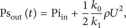
where Piin is the infinite downstream pressure, k0 is a constant, k1 is the valve opening, ρ is the air density, and U is the outlet axial flow velocity. The operating condition of the ventilation system is determined by the intersection of the fan performance curve and valve throttling line, which is directly connected in structure. The throttle condition can automatically simulate rotating stall without any manual intervention to change the back pressure.
3.4. Broadband Noise Sources Model
Broadband noise source (BNS) model mainly contains Proudman's model for quadrupole source and Curle's boundary layer model for dipole Source. Proudman using Lighthill's theory considered noise generated by a homogenous isotropic turbulence [29]. Using statistical models he derived the analytical expression for the acoustic power (AP) per unit volume. Proudman's model mainly focuses on the quadrupole source, which is also known as turbulent noise. The turbulent noise mainly caused by the separation flow and the turbulent fluctuation inside the turbulent boundary layer.
The boundary layer noise sources model is based on Curle's integral where the radiated acoustic pressure was derived as a function of the fluctuating surface pressure of the rigid body surface [32]. The surface acoustic power (SAP) radiated from each unit surface can be computed by the model which is mainly focused on the dipole source. Dipole source is also known as leaf blade force noise, which is produced by pressure fluctuation on the blade and the volute surface.
This paper focuses on the study of the aerodynamic noise sources of an axial fan during the evolution of the rotating stall. The aerodynamic noise is mainly caused by the flow separation, pressure fluctuation on the blade and volute surface, and the unsteady evolution of the stall cells. Above all, the broadband noise source (BNS) model was taken to study the variation of aerodynamic noise source during the evolution of the rotating stall. Using statistical models Mohamud and Johnson derived the following analytical expression for the acoustic power (AP) per unit volume [37]:
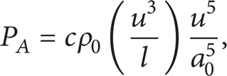
where c is a model constant. Its value is found by Proudman to be dependent on the shape of the longitudinal velocity scalar correlation function, f(r/L). For f(r/L) = exp(–r2/L2), where

Here, k is the turbulent kinetic energy. The commercial software of Fluent can also report the acoustic power in dB, which is computed from

where Pref is the reference acoustic power (Pref = 10−12 W).
4. Results and Discussions
4.1. Aerodynamic Performance
The total pressure versus volume flow curves under steady and unsteady simulations is shown in Figure 3. The curve shows the total pressure fluctuation under steady simulation when the flow rate is below 73 m3/s. The convergence with the flow of 73 m3/s is taken as the initial condition for unsteady simulation, and the convergent result can be obtained under the certain outlet back pressure. Then the valve opening k1 is set as 1, and the outlet pressure can be indirectly improved by continuously decreasing throttle valve opening until the occurrence of rotating stall in the fan. Three operating conditions of k1 = 0.97, k1 = 0.93, and k1 = 0.923 are listed on the left of the flow rate of 73 m3/s. It can be seen that the total pressure of the fan decreases gradually along with the decrease of the throttle valve, and it reaches its minimum when k1 = 0.923. Afterwards, the total pressure cannot maintain stability and fluctuation becomes larger with the decrease of throttle valve. When it comes to k1 = 0.922, wide fluctuations of the total pressure occurs, which indicates that the fan comes into rotating stall.

Total pressure versus volume flow curves.
Figure 4 further illustrates the occurrence of rotating stall with the comparison of fan outlet pressure when the throttle valve is 0.922 and 0.923. When k1 is 0.923, the outlet pressure maintains stability and the fan is still in the state of stable condition. However, the outlet pressure comes into steep drop after several rotor cycles and fluctuation shows a sine wave trend with a large magnitude when k1 is 0.922. The whole process of the outlet pressure changes indicates the process of the occurrence and development of rotating stall.

Outlet pressure history on two valve openings.
4.2. Acoustic Power Level under Five Typical Conditions
The noise in the axial fan mainly comes from aerodynamic noise and mechanical noise, wherein the aerodynamic noise, including rotation noise and vortex noise, accounts for the major part and is difficult to reduce. In order to investigate the aerodynamic noise sources and acoustic power level before and after the occurrence of stall, five different conditions are selected: k1 = 1.5, k1 = 0.922 (the 10th rotation cycle), k1 = 0.922 (the 13.5th rotation cycle), k1 = 0.922 (the 14th rotation cycle), and k1 = 0.922 (the 25th rotation cycle). The five conditions are marked as 1st, 2nd, 3rd, 4th, and 5th condition, respectively. The k1 = 1.5 condition is near the design condition. When k1 is 0.922, the stall does not occur in the 10th rotation cycle. While it occurs in the 13.5th rotation cycle and the stall cell is mature in the 25th rotation cycle.
Figure 5 shows the variation of the maximum acoustic power level in different domains of the fan before and after the occurrence of the stall. As shown in Figure 5, the maximum acoustic power level under design condition is the lowest among the five conditions, and the aerodynamic noise source of the fan is mainly the rotation noise at this time. After the occurrence of stall, the maximum acoustic power level in all domains increases significantly. This phenomenon is derived from the separation vortex which causes vortex noise due to the boundary layer separation and vortex breakdown. Due to the influence of adjacent rotor and stator domains, the maximum acoustic power level of the inlet and outlet domains has a significant increase under the 4th condition. When the fan comes to the 5th condition, which is the deep stall state, the two rotor domains have the highest maximum acoustic power level among the six domains with approximately 140∼150 dB noise level. Under the five conditions, with the decrease of flow and the development of the flow field, the maximum acoustic power level of the fan gradually increases, reflecting the great importance of rotating stall on the fan noise under low flow rate conditions. In Figure 5, It also indicates that the maximum acoustic power level in two rotor domains have the same variation law. Therefore, the paper selected the first rotor as the research objects to study the aerodynamic noise sources and acoustic power level before and after the occurrence of rotating stall.

Maximum acoustic power level under five conditions.
Figure 6 shows the contours of acoustic power level and distributions of streamline under design condition at Z = 0 section. The rotor rotates in the anticlockwise direction. It can be seen from Figure 6 that the flow field maintains stable and the acoustic power level is symmetrically distributed under design condition. 24 tiny high noise regions with 105∼115 dB acoustic power level are circumferentially distributed along the suction side near the blade tip area. This phenomenon is derived from the small scale separation vortex which causes vortex noise due to the boundary layer separation and vortex breakdown. A low noise region with 25∼45 dB acoustic power level also exists in the middle of each flow passage. Under the carrying function of air flow and the backflow effect, the low noise regions are circumferentially distributed. And due to the influence of rotation, the low noise regions are near to the pressure side of the adjacent blades.
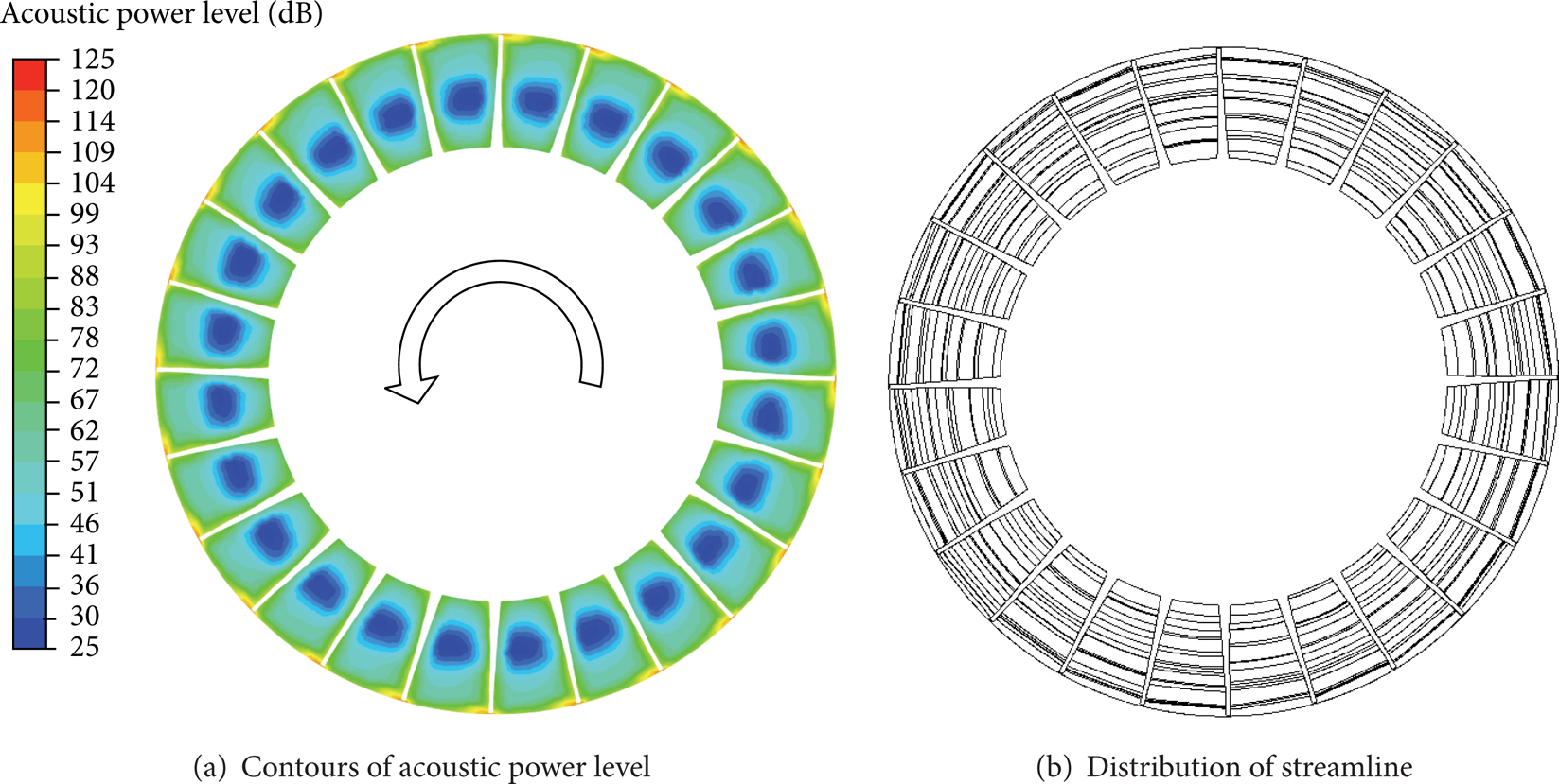
Contours of acoustic power level and distributions of streamline under design condition.
Figure 7 shows the contours of the acoustic power level of the Z = 0 section in the rotor under 4 different conditions before and after stall. The contours of the acoustic power level of the rotor at the 10th rotor cycle when the valve opening is 0.922 are illustrated in Figure 7(a). At this moment, the fan is at the near stall condition. According to the Figure, the acoustic power level in the rotor is evenly distributed along the circumferential direction. Compared to Figure 6(a), the number and level of the noise areas do not show obvious change. However, since positive incidence increase with the decrease of flow rate, leading to the increase of rotation noise, the high noise regions near the blade tip significantly increases, covering almost the entire region of the tip clearance. The low noise regions in the middle of the flow channels expand toward the blade tip and root with elliptical distribution.
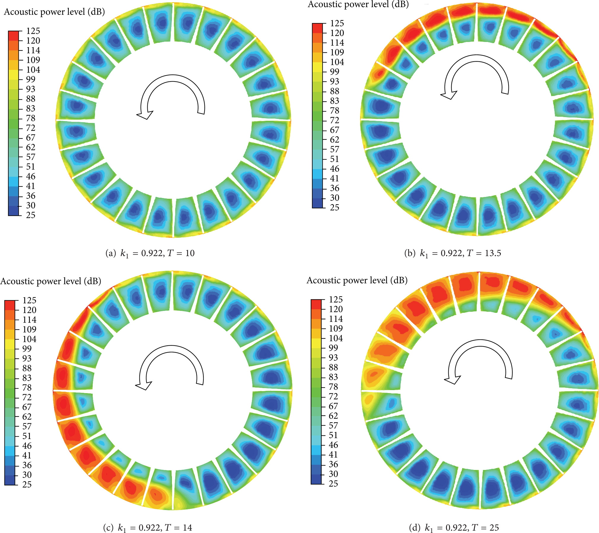
Contours of acoustic power level on four different conditions.
When it comes to the condition as shown in Figure 7(b), stall inception occurs. It can be seen that the flow field in the impeller cannot maintain even distribution, and five flow channels among the eight consecutive flow channels significantly influenced by stall inception suffer the worst damage. The original high noise regions near the blade tip develop into a large-scale noise area covering the region from the blade tip to the 70% blade height, and the acoustic power level also increases significantly, which is about 100∼130 dB. The high noise regions in the three channels affected by stall inception along the clockwise direction also show the trend to expand, and the low noise regions in the middle of channels are suppressed with the decrease of acoustic power level, while the high noise regions of anticlockwise direction decrease in the three channels. This is because the rotating speed of stall inception is lower than that of impeller and the flow field along the propagation direction of stall inception is affected.
The contours of the acoustic power level of the rotor at the 14th rotor cycle when the valve opening is 0.922 are shown in Figure 7(c). It can be seen that the acoustic power level shows uneven distribution in the flow channels during stall, and large-scale high noise regions occur in ten consecutive channels. Compared with Figure 7(b), the scale of the noise regions becomes larger while the acoustic power level remains the same. The high noise regions in 6 channels cover almost half of the channels, and the corresponding low noise areas reduce to 1/8 of those in the channels without the influence of stall.
When it comes to the condition as shown in Figure 7(d), stall inception turns into mature stall cell which rotates with a certain speed. As shown in the Figure, the uneven distribution of flow field in circumferential direction becomes more serious. The flow field in 11 consecutive flow channels where stall cell occupies in the impeller is severely damaged. Compared with Figure 7(b), the scale of the high noise regions in the 11 flow channels increases significantly while the acoustic power level remains to be 110∼130 dB. And the high noise areas in the three channels which suffer the most severe damage almost occupy the entire flow passage with the low noise regions gone. In the three channels near to the stall cell along the rotating direction, the area with high noise increases in the evolution process from stall inception to stall cell, while the flow field in the two channels in the opposite direction is improved and recover from stall. Compared with the acoustic power level during stall inception in Figure 7(b), the noise level in Figure 7(d) is much larger.
Three different sections are selected to study the acoustic power level characteristics along the radial direction, which are 10%, 50%, and 95% blade height sections.
Figure 8 shows the contours of acoustic power level on three different radial sections when k1 is 1.5. As shown in Figure 8, there are 24 high noise regions located near the trailing edge uniformly distributed along the circumferential direction in each section. This is because there is a small area of boundary layer separation near the trailing edge of the blade, and the velocity gradient is relatively large. It can also be observed that the 50% blade height section has the lowest acoustic power level, while the maximum appears on the 95% blade height section as the tip leakage flow.
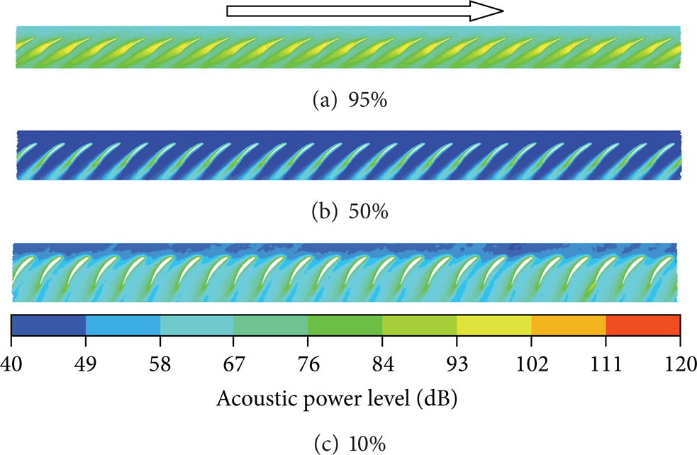
Contours of acoustic power level at radial sections when k1 is 1.5.
Figure 9 shows the contours of acoustic power level at three radial sections when k1 is 0.922 at the 10th rotation cycle. As shown in Figure 9, the area of high noise regions and the noise level are both increased in each blade height section. On the 95% blade height section, there are two high noise regions with approximately 105∼115 dB noise level in each flow channel which are located in the 1/2 chord of the suction surface and the trailing edge separately. Comparing Figure 8(c) with Figure 9(c), on the 10% blade height section, the high noise regions which are located near the trailing edge of the blade are increased significantly. This is because the separation of boundary layer in each blade surface will form some separation vortexes near the trailing edge, which lead to the enhancement of vortex noise level.
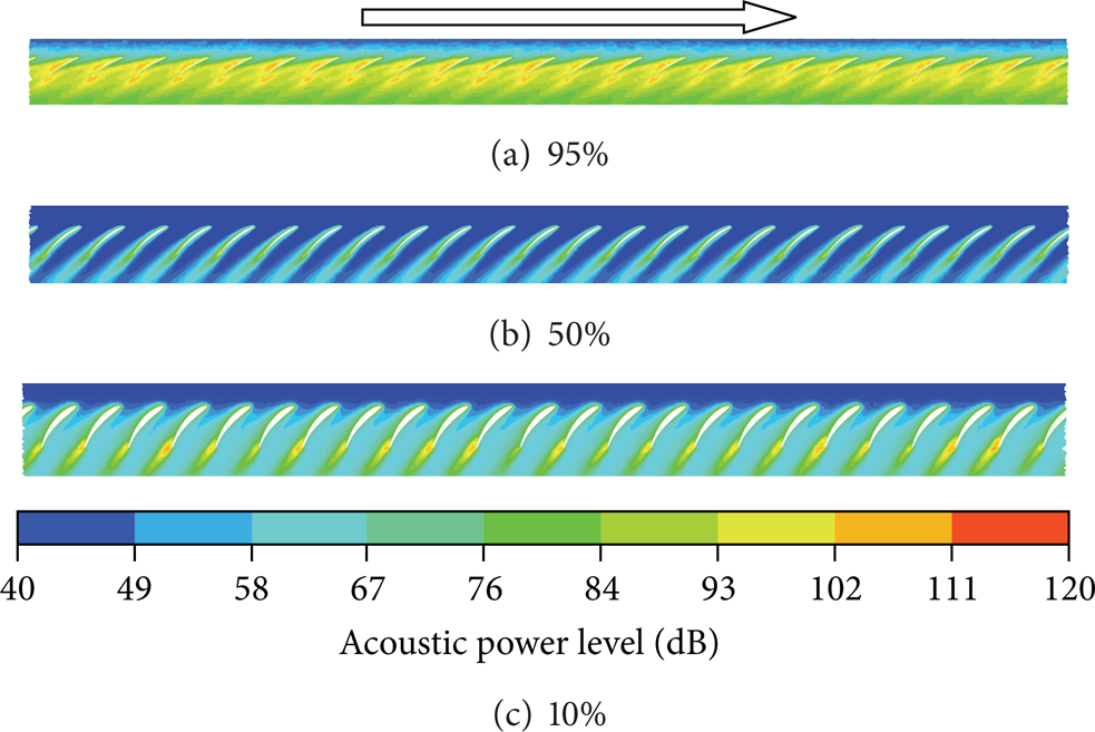
Contours of acoustic power level at radial sections when k1 is 0.922 at the 10th rotation cycle.
Figure 10 shows the contours of acoustic power level at three radial sections when k1 is 0.922 at the 13.5th rotation cycle. The figure shows that the acoustic power level distribution along the circumferential direction is uneven. On the 95% blade height section, the high noise appears in 8 consecutive impeller channels with a noise reduction in other impeller channel outlet. There is a consecutive high noise area on the 50% blade height section which occupied five impeller channels. Since the stall inception occurs under this condition and the separation vortex and flow blockage occur in the channels, several high noise regions appear. While in other impeller channels, flow rate increases and incidence angles decrease, which result in flow improvement and noise level reduction.

Contours of acoustic power level at radial sections when k1 is 0.922 at the 13.5th rotation cycle.
Figure 11 shows the contours of acoustic power level at three different radial sections when k1 is 0.922 at the 14th rotation cycle. Compared with Figure 10, on the 95% blade height section, the affected regions of high noise expand circumferentially, and the high noise regions occupy 10 impeller channels, while 7 impeller channels appear obviously in high noise regions on the 50% blade height section. No difference can be observed between Figures 11(c) and 10(c) as the stall cell has not extended to the 10% blade height section.
Contours of acoustic power level at radial sections when k1 is 0.922 at the 14th rotation cycle.
Figure 12 shows the contours of acoustic power level at three different radial sections when k1 is 0.922 at the 25th rotation cycle. As shown in Figure 12, the high noise regions appear in 11 consecutive impeller channels on the 95% blade height section. On the 50% blade height section, the number of the impeller channels occupied by the high noise regions is 8. As shown in Figure 12(c), obviously high noise region can be observed on the 10% blade height section, and it occupies four impeller channels.

Contours of acoustic power level at radial sections when k1 is 0.922 at the 25th rotation cycle.
4.3. Acoustic Power Level Characteristics during Circumferential Propagation of Stall Cell
The contours of acoustic power level and distributions of streamline at the Z = 0 section, as shown in Figure 13, are analyzed to study the propagation law of the high noise regions during the circumferential propagation of stall cell. At the four moments which are 50th, 50.25th, 50.5th, and 50.75th rotation cycle, the fan is in deep stall and the valve opening k1 is 0.922. The time interval of each moment is 1/4 rotation cycle and the impeller rotates along the anticlockwise. As shown in Figure 13, the high noise regions with 110∼130 dB noise level appear in 11 continuous impeller channels which is occupied by the stall cell, and the high noise regions develop into a large high noise region with a higher acoustic power level, while in the other impeller channels, due to the improvement of flow, low noise regions appear and are evenly distributed. Figure 13 illustrates that the high noise areas rotate with the stall cell at the same speed along the circumferential direction.

Contours of acoustic power level and distributions of streamline.
It also can be observed from Figure 13 that the high noise regions pass 9 impeller channels along the anticlockwise direction during the 0.75 rotation cycle, while the impeller passes 18 channels. It shows that the high noise regions rotate along the same direction with impeller in the absolute coordinate system. While in the relative coordinate system, the high noise area spreads along the clockwise direction at a half of rotor speed.
4.4. Frequency Domain Characteristics before and after the Occurrence of Stall
The noise of rotor 1 in frequency domains is simulated using the large eddy simulation (LES) and FW-H noise model. Through the fast Fourier transform (FFT) process, the far-field aerodynamic noise pressure level distribution of the fan before and after the occurrence of stall is acquired. As shown in Figure 14, the numerical probe is arranged in the tip clearance domain.

The location of the numerical probe.
Figure 15 shows the noise spectrogram of the rotor 1 under the 1st and 5th conditions. As the rotating speed of the fan is 1490 rpm and the number of moving blades is 24, the blade passing frequency (BPF) of the fan is 596 Hz. As shown in Figure 15(a), the first peak value appears when the frequency is about 596 Hz, which is the same as the BPF. The other peak value appears when the frequency is about the integer multiples of the BPF. The sound pressure level gradually reduces with the increase of frequency and the maximum of sound pressure level is all in the frequency bands less than 1500 Hz. It can be indicated that the aerodynamic noise of the fan is the low frequency noise, which is mainly caused by the rotation of the rotor 1 under the 1st condition.
Noise spectrogram of the rotor 1 under different conditions.
After the occurrence of the stall, as shown in Figure 15(b), the tip leakage vortexes and boundary layer separation lead more intense fluctuation of the sound pressure level. The characteristics of discrete peak in low frequency band become weak gradually, while the broadband noise in middle frequency bands increased significantly. Meanwhile, the high frequency band derives multiple discrete peaks. Comparing Figure 15(a) with Figure 15(b), the aerodynamic noise of the fan has developed from the discrete rotation noise to the wide-band eddy current noise.
5. Conclusions
In this paper, the phenomenon of rotating stall in an axial fan is numerically studied. The analysis of the acoustic power level characteristics under different stall conditions is conducted. The conclusions can be drawn as follows.
The variation of the maximum acoustic power level of the fan before and after the occurrence of rotating stall is analyzed. The aerodynamic noise source of the fan is mainly the rotation noise under the design condition. Once flow decreases and fan enters rotating stall, the vortex noise accounts for the major part of fan aerodynamic noise, and the maximum acoustic power level of the fan appears in the rotor domains.
The acoustic power level characteristics during the generation and development of stall inception are discussed. When the fan comes to the near stall condition, the separation of boundary layer in each blade surface will form some separation vortexes near the trailing edge, which leads to the enhancement of noise level. At the evolution process from the stall inception to the stall cell, the high noise regions develop along the radial, circumferential, and axial directions, and the number of channels occupied by high noise regions increases from 8 to 11.
The acoustic power level characteristics during the circumferential propagation of stall cell are investigated. On rotating stall condition, the high noise regions occupying 11 impeller channels propagate with the stall cell along the circumferential direction at a half of rotor speed. While in other channels, acoustic power level is low and evenly distributed. The influence mechanism of rotating stall on the acoustic power level characteristics is revealed.
Conflict of Interests
The authors declare that there is no conflict of interests.
Footnotes
Acknowledgments
The authors gratefully acknowledge the support provided to this research by Natural Science Foundation of Hebei Province, China (Grant no. E2012502016) and Fundamental Research Funds for the Central Universities, China (Grant no. 2014MS113).