
Abstract
Traveling wire electrochemical machining is a promising approach for the fabrication of various metal parts. However, the stray-current attack deteriorates the surface quality while it is employed to cut thick workpiece as a normal pulse or DC is used. In this paper, the characteristics of the stray-current attack in reciprocated traveling wire electrochemical machining are firstly identified, and special insulating methods are proposed to reduce the effect of the stray-current. The model of electric field is built. Both the simulation and the experimental results illustrate that the stray-current attack can be reduced significantly by the proposed insulating methods. Finally, structures with fine surface quality on stainless steel 304 with thickness of 20 mm were successfully produced.
1. Introduction
Electrochemical machining (ECM) is a nontraditional machining process, in which the conductive materials are dissolved by anodic electrochemical reactions at atomic sizes. ECM has many advantages in processing metallic materials, regardless of their hardness and high strength, high tension, or whether they are heat-resistant metals, such as no tool wear, stress-free processing, and the ability to produce smooth surfaces and to machine complex structures. ECM has widely been accepted in the aerospace, automotive, and micromachining industries [1–6].
Wire electrochemical machining (WECM) is a special type of ECM, which uses a metal wire as the tool cathode, rather than a preformed cathode in typical ECM. WECM inherits the advantages of ECM while avoiding the requirement for tool design, which is a costly, complex, and time-consuming process in the typical ECM process. WECM also has no requirement to design a complicated flow channel. Moreover, the wire electrode in WECM may be used repetitively because it is not worn out. WECM is a flexible technology that can be used to cut various metal parts by moving the wire electrode or the workpiece along a programmed path [7–16].
This technology can nowadays be applied at a micrometre scale and is called microwire electrochemical machining (Micro-WECM). In Micro-WECM, the use of ultrashort pulse, in which frequency and duration are, respectively, much higher and much shorter than normal pulse, improves the machining accuracy significantly. When an ultrashort pulse is applied, the dissolution of a workpiece can be confined to the region very close to the tool electrode because of the charge and discharge behavior of the double layer capacitance. Micro-WECM enables the fabrication of precise features on a thin workpiece, such as a microhelix, a microgear, and a microchannel. Typically, the thickness of workpiece cut by Micro-WECM is less than 100 μm [10–13].
However, when WECM is used to cut a thick workpiece (thickness is more than ten millimeters), the ultrashort pulse supply might not be used because the power of an ultrashort pulse supply is insufficient. Moreover, it is notably difficult to remove the electrolysis products and renew the electrolyte in the machining gap as the machining gap is ultradeep and narrow. Therefore, DC or normal pulse power supply and special methods, which can enhance the mass transport rate in the machining gap, are introduced to cut a thick workpiece in WECM. Wang et al. reported that microstructures on stainless steel 304 with thickness of 5 mm were machined by WECM with direct current and the electrolyte flushing along the wire [14]. Zeng et al. revealed that wire traveling is capable of producing microstructures having feature heights up to ten millimetres and feature aspect ratios of 50 or more [15]. Qu et al. demonstrated that the combination of pulse ECM (the frequency of the pulse power is less than 10 KHz) and a reciprocated traveling wire electrode can improve the homogeneity of slit by the timely replenishing of the electrolyte within a narrow machining gap and removal of electrolysis products, and a microstructure with slit width of 177 μm with a standard deviation of 1.5 μm and an aspect ratio of 113 was fabricated on a stainless steel substrate measuring 20 mm in thickness [16].
While the DC or normal pulse power supply was used in WECM, the workpiece might suffer from the stray-current attack, which leads to poor surface quality. When the power is turned on, the electric fields are distributed far from the tool, thereby enabling the stray-current attack to easily occur on the workpiece due to electric current lines acting over this zone. In a typical ECM process, many efforts have been continuously attempted by the research community to minimize the stray-current attack. The essence of this issue is to localize the current affected zone, which is typically minimized by electrode insulation coating [17]. In addition, novel electrodes, such as a dual pole tool [18], thief-anodes [19], and an auxiliary electrode [20], have been proposed to change the current distribution and control the magnitude of the stray-current attack. Additionally, other attempts have involved optimizing the process conditions that could influence the electrochemical behaviors. Passivity electrolyte was introduced for its ability to block the dissolution at the area of low current density by introducing a threshold value of current density [21]. The use of pulsed current [22–24], especially ultrashort pulses [3, 4], is another progressive technique used to obtain high precision in ECM. Review of the literature has revealed that there is hardly any literature concerning this problem in traveling wire electrochemical machining. As the wire is moving along its axis during the machining process, the conventional insulation coating might not be used.
In this paper, to cut a thick workpiece, the normal pulse power was used and a reciprocated traveling wire was introduced to remove the electrolysis products and renew the electrolyte quickly from the narrow machining gap. The characteristics of the stray-current attack in reciprocated traveling wire electrochemical machining are firstly identified and special insulating methods are proposed to reduce the effect of the stray-current. According to the simulation analysis, a series of experiments were conducted. Finally, structures with a thickness of 20 mm in stainless steel (SS 304) were successfully produced with fine surface quality using the proposed insulating methods.
2. Analysis of the Stray-Current Attack
Figure 1 illustrates the principle of the reciprocated traveling wire electrochemical machining. The wire acts as the cathode and the workpiece acts as the anode. The wire is traveling along its axis, and the traveling direction can be periodically altered by using a position switch. During the machining process, both the wire electrode and the workpiece are immersed in the electrolyte, and the workpiece profile can subsequently be formed by controlling the workpiece feed trajectory. The electrolyte is forced to flow in the machining gap as the wire is traveling.

Schematic view of reciprocated traveling wire electrochemical machining.
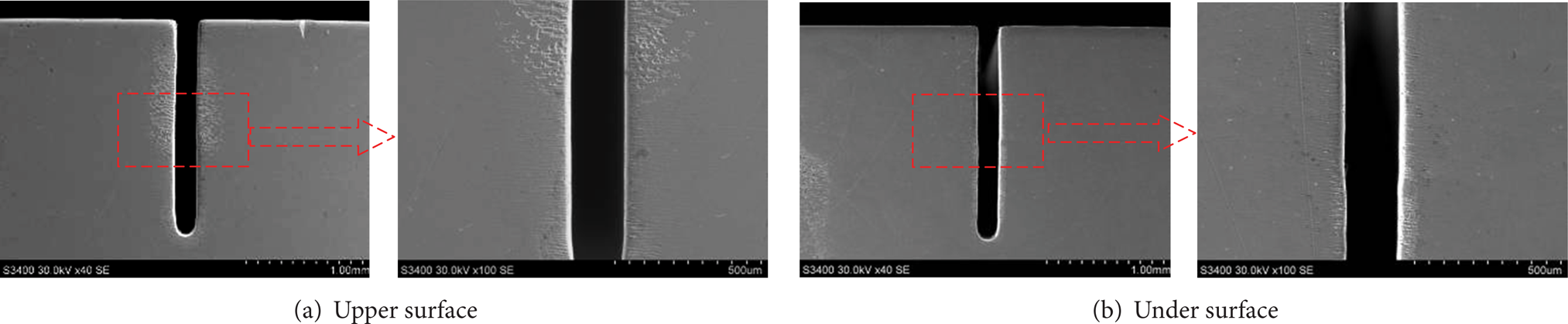
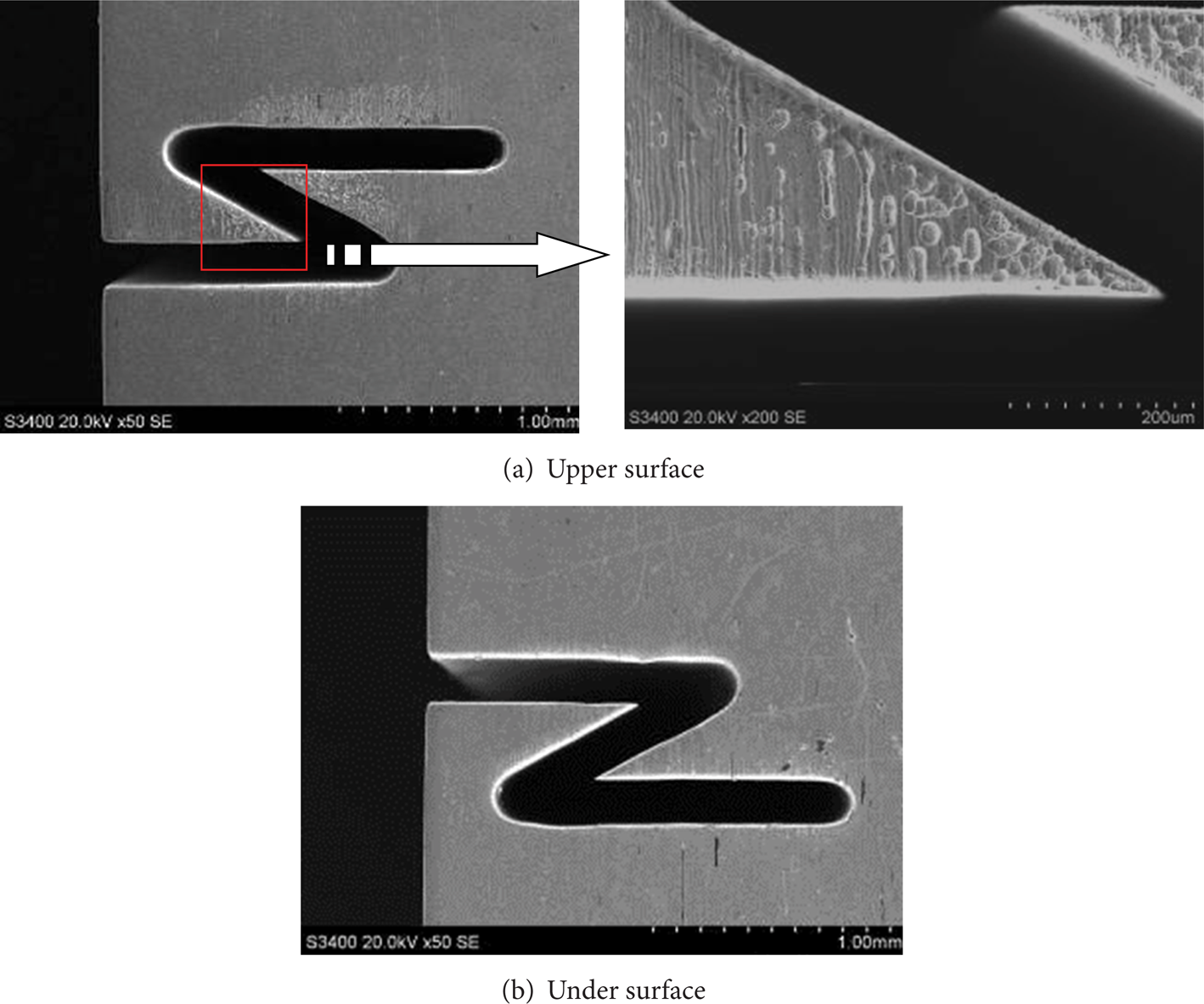
Figure 2 shows example of slit fabricated using this technology. It is obvious that the upper surface of the workpiece suffers from more serious pitting corrosion, which is caused by the stray-current, than the under surface and that the pitted surface zone is discontinuous. These phenomena are quite different from those in a typical ECM process. Figure 3 schematically illustrates the wire traveling direction and the pitting corrosion formed on the workpiece surface near the slit edges during the machining process. On the basis of Figure 3, the influence of the stray-current is observed to be related to the wire traveling direction. The reason for this relationship is explained in the following.
Slit machined by reciprocated traveling wire electrochemical machining.

Schematic view of the pitting corrosion distribution on the workpiece surface.
In an electrolytic process, the current density j is defined by the electric field intensity and the electrolyte conductivity; that is,

where E is the electric field intensity and κ is the electrolyte conductivity, which could be changed by the electrolysis product and the electrolyte temperature as follows [15]:

where κ0 is the initial electrolyte conductivity, α is the temperature coefficient of the electrolyte conductivity, ΔT is the electrolyte temperature rise, β is the volume fraction of hydrogen and hydroxide sludge, and n is a constant ranging from 1 to 2.
Figure 4 depicts the distribution of the current lines in WECM, while the electrolyte conductivity is uniform. As shown in this figure, the distribution of electric flux lines is far from the tool, and material removal might occur in this zone. However, during reciprocated traveling wire electrochemical machining process, whether this zone undergoes dissolution or not is determined by the wire traveling direction, which affects the electrolyte conductivity in this zone. If the electrolyte conductivity is reduced to a sufficiently low level such that the current density over this zone is below a threshold value, then the material dissolution process is cut off.

Current lines distribution while the electrolyte conductivity is uniform.
Figure 5 schematically shows the view of the transportation of the electrolysis products, namely, the hydroxides and the hydrogen bubbles, under different directions of wire travel.

Schematic view of the distribution of the electrolysis products for different wire traveling directions. (a) Traveling downward. (b) Traveling upward.
As shown in Figure 5(a), when the wire electrode is traveling downward, the direction of the wire travel is the same as that of gravity. Almost all of the hydroxides outflow from the lower end of the machining gap due to the effect of both the traveling wire and gravity. As the hydroxides accumulate onto the workpiece under surface, the electrolyte conductivity in this zone (zone 2) is greatly reduced. As a result, the stray-current density becomes so small that material dissolution might cut off. However, there is little hydroxides accumulated onto the workpiece upper surface, and the electrolyte in this zone (zone 1) is fresh. Therefore, the pitting corrosion in zone 1 is much more serious than that in zone 2 when the wire is traveling downward.
However, the situation changes when the direction of the wire traveling is opposite to that of gravity, as shown in Figure 5(b). Most of the electrolysis products could be brought out from the top of the machining gap by the traveling wire and accumulate onto the workpiece upper surface. However, some hydroxides, which are too large or close to the workpiece under surface, cannot be removed by the traveling wire. These hydroxides drop out from the lower end of the machining gap under the influence of gravity. Therefore, the electrolyte conductivity in zone 3 and zone 4 are both reduced by the electrolysis products when the wire is traveling upward. In addition, the change of the electrolyte conductivity in zone 4 is less than that in zone 3, because of the small amount of dropped products by gravity. Thus, the pitting corrosion in zone 4 is more severe than it is in zone 3.
To conclude, the electrolysis products accumulated on the workpiece surface have positive effects on reduction of the stray-current attack and the most serious stray-current attack, namely, pitting corrosion, occurs on the workpiece upper surface (zone 1) when the wire is traveling downward.
3. Methods to Reduce the Stray-Current Attack
A combination of insulating methods, namely, the use of insulating tubes assisted with the shielding box, was used to reduce the effect of stray-current caused by the wire electrode and the pulleys on the workpiece surface, as shown in Figure 6. The insulating tubes are closed to both sides of the workpiece surfaces and it is hollow inside to allow the wire electrode to pass through. The shielding box includes two parts, which were connected by screws. The lower pulleys (pulley 1 and pulley 2) are fixed in the shielding box as a guide for the traveling wire electrode. In addition, the applied pulsed power supplies the required voltage to enhance the machining accuracy and the transportation of the electrolysis products. Using these methods, the distribution of the electric field will be localized and the effect of the stray-current on the workpiece surface can be reduced to some extent.

Schematic view of the insulating method combination.
4. Analysis of the Current Density Distribution
Among the methods to reduce the stray-current attack in reciprocated traveling wire electrochemical machining that are mentioned above, the insulating tubes provide the greatest contribution. Therefore, an electric field model was established to analyze the effect of the insulating tubes on the current density distribution on the workpiece surface, as shown in Figure 7. In Figure 7, ⊿ s is the machining side gap, b is the distance between the insulating tube and the workpiece, d is the inner diameter, and D is the outer diameter of the insulating tube.

Model of the electric field with the wire electrode coated with an insulating tube.
The electric field model is established with some assumptions as follows.
The process of traveling WECM is in a state of equilibrium, and the electrolyte is isotropic.
The electric parameters, such as electrolyte conductivity and temperature, are considered to be constant.
The concentration polarization, the electrochemical polarization, and the boundary effect are negligible.
Two equipotent surfaces are formed on the cathode and the anode, and the other boundaries are closed or approximately closed.
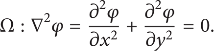
The electric potential, namely, φ(x,y), within the region Ω can be described by Laplace's Equation. That is
Then, the boundary conditions are
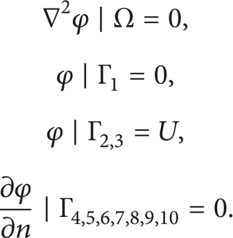
From (3) and (4), the distribution of electric potential can be calculated. Then, the current density distribution can be obtained from (1).
COMSOL software was used to simulate the current density distribution based on the model. The voltage U was set to 13 V and the machining side gap ⊿ s was set to 40 μm. The current density value of each point on the workpiece surface was normalized as

where j max (i) is the maximum current density for each simulation and j(i) is the current density of every point on the anode surface. It is noted that the maximum current density varies with the simulating conditions.
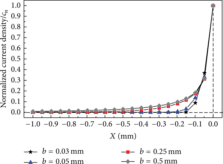
As shown in Figures 8, 9, and 10, the distribution of the current density varies with the change of both the distance b and the insulating tube dimensional size. When the insulating tube inner and outer diameters are constant, the closer is the distance b, the smaller is the current density distribution range and the more rapidly decreasing is the speed of the current density from the slit edge, as shown in Figures 8(a)∼8(d) and 9. That is, the zone where the stray-current attack might occur is localized as the distance b decreases. It is also noted that most of the current lines could be confined in the range of the tube inner diameter when the distance b decreases down to 0.05 mm and there is no necessity to further decrease the distance in practical application. Moreover, the influence of the insulating tube dimensional size on the current density distribution was also investigated. As shown in Figures 8(c), 8(e), 8(f), and 10, the insulating tube with a smaller inner diameter is more preferable to localize the current density distribution when the distance b is constant. However, a smaller inner diameter might increase practical difficulty.

Current lines distribution with the insulating tube.
Influence of distance b on the current density distribution.

Influence of insulating tube dimensional size on the current density distribution.
According to the analysis above, the insulating tube can localize the current density distribution and decrease the risk of stray-current attack on the workpiece surface while the distance between the insulating tube and the workpiece is not more than 0.05 mm for a suitable tube inner diameter. In this way, a higher surface quality can be obtained.
5. Experimental Verification
5.1. Experimental System
The self-developed experimental system of reciprocated traveling wire electrochemical machining is shown in Figure 11. The system consists of a machining feed system, an electrolyte circulation system, and a traveling wire control system. The machining feed system controls the expected motion of the workpiece, and the electrolyte supply is sustained through the use of pump 1. In addition, the flocculent electrolysis products are purified by the filter to prevent their influence on the machining. The wire electrode travels in consecutive paths and changes traveling direction by the actuation of a position switch fixed on the machine base. Pump 2 is used to remove the electrolyte in the shielding box. The apparatus of the insulation is shown in Figure 11(b).

The experimental system for reciprocated traveling wire electrochemical machining.
5.2. Experimental Arrangement
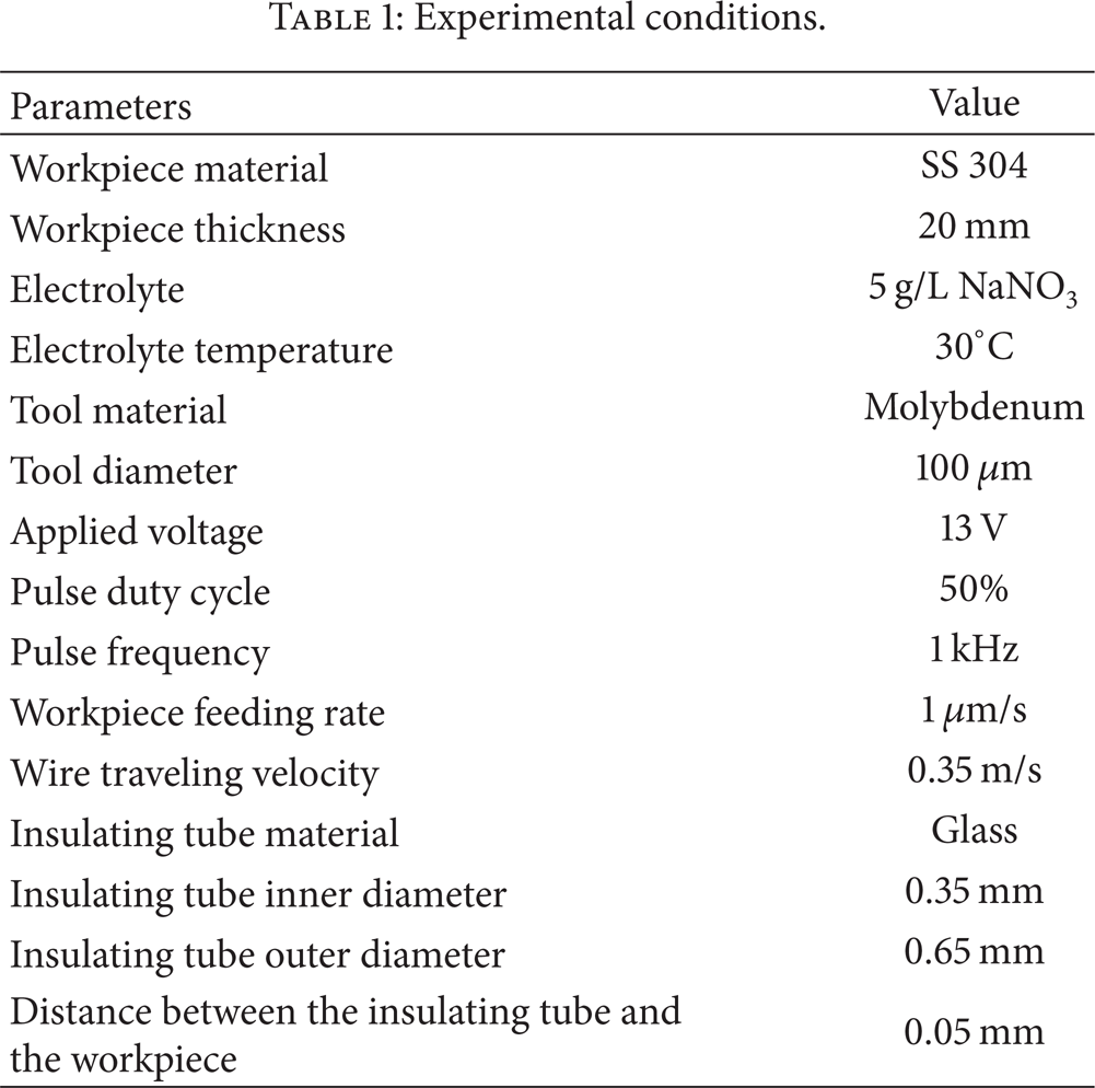
The experiments were conducted with and without insulating methods to verify whether the stray-current attack could be reduced by the proposed insulating methods. From the analysis described above and practical feasibility, the glass tubes with small inner diameter of 0.35 mm were used as the insulating tubes, and the distance between the insulating tube and the workpiece was set to 0.05 mm in the experiments. The experimental conditions are listed in Table 1. Thereafter, experiments were conducted to fabricate structures on stainless steel samples measuring 20 mm in thickness. The machined surface is observed and measured by a scanning electron microscope (S-3400N, Hitachi, Japan).
Experimental conditions.
5.3. Experimental Results
Figures 12 and 13 show the structures fabricated using reciprocated traveling wire electrochemical machining without and with insulating methods, respectively. The thickness of the samples is 20 mm. As shown in Figure 12, the pitting corrosion, which was caused by the stray-current and deteriorates the surface quality seriously, is remarkably apparent when the structure was machined without insulating methods. In addition, the characteristics of the pitting corrosion are in accordance with the analysis before. In contrast, there is no obvious pitting corrosion on the structure surface when the insulating methods were used, as shown in Figure 13. The experimental results indicate that the proposed insulating methods are quite effective to reduce the stray-current attack and improve the surface quality in reciprocated traveling wire electrochemical machining.
Structures fabricated without insulating methods.

Structures fabricated with insulating methods.
By the application of the proposed method, other structures with fine surface quality on stainless steel 304 with thickness of 20 mm were also obtained as shown in Figure 14.

Structures with fine surface machined by reciprocated traveling wire electrochemical machining.
6. Conclusions
The characteristics of the stray-current attack in reciprocated traveling wire electrochemical machining were identified in this paper. In addition, insulating methods were proposed to reduce the stray-current attack. The conclusions can be summarized as follows.
The stray-current attack in reciprocated traveling wire electrochemical machining is significantly affected by the wire traveling direction, and the upper surface of the workpiece suffers the most serious stray-current attack when the wire is traveling downward.
The simulation results reveal that the closer is the distance between the insulating tube and the workpiece, and the smaller is the tube inner diameter, the less stray-current attack will appear on the workpiece surface.
The experimental results indicate that the application of the insulating methods is a notably effective approach to reduce the stray-current attack and improve the surface quality in reciprocated traveling wire electrochemical machining.
Structures with fine surface quality on stainless steel 304 with thickness of 20 mm can be successfully fabricated using reciprocated traveling wire electrochemical machining if the insulating methods are used.
Conflict of Interests
The authors declare that there is no conflict of interests regarding the publication of this paper.
Footnotes
Acknowledgments
This work was conducted under the sponsorship of the National Natural Science Foundation of China (51375238) and the Jiang Su Natural Science Foundation (BK20131361).