
Abstract
Form grinding is a popular finishing process in manufacturing cylindrical gears with tooth flank modification. The tooth flanks are usually twisted when a lead crowning is performed only through additional radial motion during double flank grinding. For solving the problem, this paper proposes a method for application of tooth lead crowning without twist in cylindrical helical gears based on the idea of tooth form correction for spiral bevel and hypoid gears. In this method, the motion of each following axis is formulated as a six-order polynomial of the leading axis position and the sensitivity of tooth ground flanks with respect to the changes in the motion polynomial coefficients is analyzed. Polynomial coefficients for lead crowning are optimized by minimizing the errors between the ground tooth flanks and the target tooth flanks. The proposed optimization procedure uses dynamic sensitivity matrix instead of static, and it can obtain optimum solution with fewer steps stably. Simulation and experimental results demonstrate the effectiveness of this twist preventing method.
1. Introduction
Cylindrical gears are essential machine elements and widely used in many fields, such as wind power, coastal ships, automotive products, and general gear boxes. In the process chain of gear manufacturing, gear grinding is a kind of hard fine machining processes after premachining and heat treatment. Gear grinding is a necessary final process step to achieve accurate tooth flanks [1]. Profile and lead modifications (or tooth trace modification) are more applied in the past years to fulfill high torque load demands and low running noise [2]. Form grinding is the most suitable process for achieving flexible profile and lead modifications on the finished tooth flanks. Tooth profile modification means deviation of cross profile from an involute one, while the other one means deviation in longitudinal direction from a helicoid surface [3].
It is feasible to produce tooth profile modified gears accurately by designing the wheel axial profile using the mathematical model established by You et al. [4]. However, in order to perform tooth lead crowning additional relative motions must be introduced between the grinding wheel and the work gear in the grinding process. There are commonly three kinds of additional motions: the approaching motion in the radial direction, the additional screw motion of the work gear, and the tangential motion of the grinding wheel [5]. Among these additional motions, the first one is mostly used, because it can be performed during double flank grinding, which is more efficient compared with single flank grinding. But the additional approaching motion would generate twist errors when grinding gears with a lead crowning [2]. Kobayashi et al. [6] found that the amount of twist can be reduced by optimizing the setting angle of the grinding wheel. Li et al. [7] proposed a method to reduce the twist errors through optimizing the axial profile of the grinding wheel, and the effects are limited. More recently, Fan et al. [8] investigated the sensitivity of the changes of tooth flank form geometry to the changes of universal motion coefficients for face-milling spiral bevel and hypoid gears, and they optimized the motion coefficients for reducing the tooth flank form errors. Gabiccini et al. [9] discussed the reliability and robustness of different optimization algorithms for gear surface topography corrections. Nonetheless, no twist preventing method for lead crowning during double flank grinding has been investigated in detail.
The purpose of this paper is to realize lead crowning without twist based on the method used for spiral bevel and hypoid gears. First, we establish a mathematical model of the ground tooth flanks based on a universal CNC (computer numerical control) gear profile grinding machine. Subsequently, the sensitivity of the changes of the ground tooth flanks to the changes of motions of following axes is analyzed. After the polynomial coefficients are optimized by dynamic sensitivity matrix, the lead crowning can be produced without twist. At last, the validity of this twist preventing method is demonstrated experimentally.
2. Mathematical Model for the Ground Tooth Flanks
As widely recognized, the gear form grinding process is mainly divided into two stages: the dressing stage and the grinding stage. In the dressing stage, the wheel is shaped by a diamond dressing roll. Then the dressed wheel will be used to grind the tooth flanks in the grinding stage. The axial profile of the grinding wheel depends on the target work-gear surface, the center distance between the work gear and the grinding wheel, and the setting angle of the grinding wheel. Several methods for calculating the wheel profile have been reported by researchers over the past decades [10, 11].
Conventionally, the calculation of the wheel axial profile is called forward calculation in form grinding process. And backward calculation means calculating the tooth surfaces of gear ground with the given wheel and specified relative motions between the wheel and the work gear. Backward calculation is usually used for validating the calculated shape of the grinding wheel and analyzing the influence of machine errors and motions upon the ground tooth flanks. In this section, the mathematical model of backward calculation is built based on a universal CNC gear profile grinding machine.
As Figure 1 shows, the universal CNC gear profile grinding machine has five numerically controlled axes: three rectilinear axes and two rotational axes. The signs D x , D y , and D z denote the rectilinear motions in radial, tangential, and axial directions, respectively. At the same time ψ a denotes the swivel angle of the grinding wheel, and ψ c denotes the rotation angle of the work gear. In the dressing stage, the tangential axis and the axial axis are used for positioning the grinding wheel. In the grinding stage the axial axis is coupled to the work-gear rotation axis for producing a relative screw motion between the work gear and the grinding wheel.
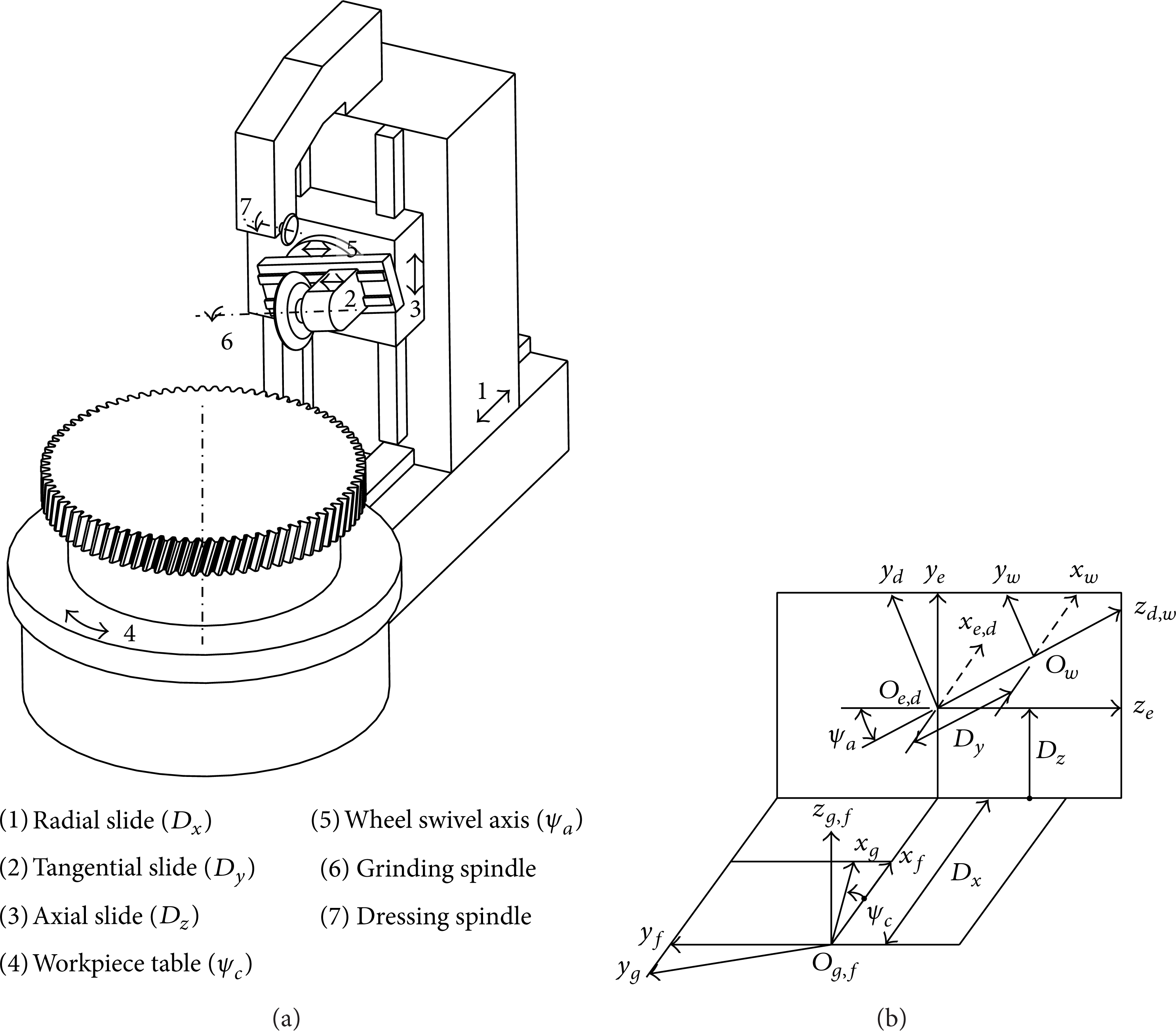
Five-axis gear profile grinding machine: (a) structure of the machine; (b) coordinate systems for grinding stage.
As illustrated in Figure 1, we set up five coordinate systems: S g that is rigidly connected to the work gear, S w that is rigidly connected to the grinding wheel, S d and S e that are rigidly connected to the wheel swivel axis and the axial slide, respectively, and the fixed coordinate system S f that is rigidly connected to the frame of the grinding machine. The auxiliary coordinate systems S d , S e , and S f are used to relate coordinate systems of the work gear and the grinding wheel.
As shown in Figure 2(a), the axial profile of the grinding wheel is a planar curve h-h and is represented in a coordinate system S p as

where u is the variable parameter that determines the location of a current point on h-h. The wheel surface is regarded as being swept by the curve h-h while the coordinate system S p rotates about the zw axis as Figure 2(b) shows. So the wheel surface Σ w can be expressed in the coordinate system S w as

The 4 × 4 matrix


The wheel surface generated by the axial profile: (a) the axial profile of the wheel; (b) illustration of coordinate systems S f and S w .
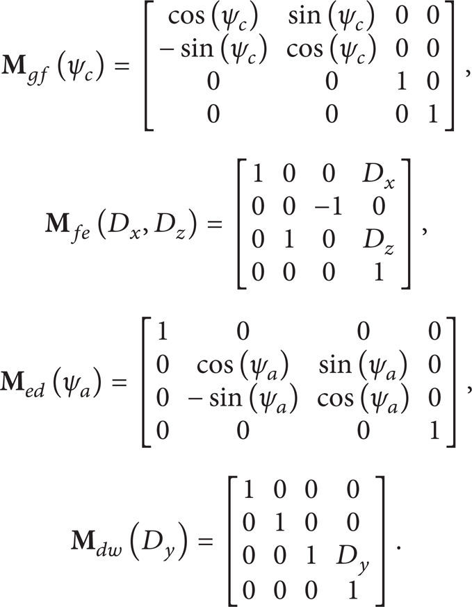
As the grinding wheel grinds a tooth gap, the locus of the wheel surface {Σ w } can be represented in work-gear coordinate system S g as
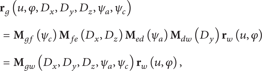
where
As the correction method is used for spiral bevel and hypoid gears [8], the motions of the following axes are formulated as polynomials of the leading axis position:
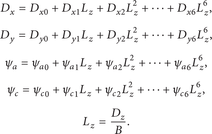
Here, L z is defined as normalized representation of the axial slide motion (leading axis); B is the tooth width.
As is evident, D
x
, D
y
, D
z
, ψ
a
, and ψ
c
are all functions of L
z
. So the locus of the wheel surface {Σ
w
} can be represented as

where

3. Optimizing the Axis Motions for Tooth Lead Crowning
3.1. Deviation of the Ground Tooth Flanks
Due to geometric, kinematic, thermal, principal, and other errors, the ground tooth flanks generally deviate from the target ones. Error evaluation is an essential step to improve the accuracy of machine tools through design and manufacturing, compensating by software or eliminating the error sources. As shown in Figure 3, the ground and standard flanks are compared at 126 (2*7*9) grid points. The standard flank means a theoretical involute tooth flank without any profile or longitudinal modifications. As shown in Figure 3(a), while calculating the deviations of each ground flank from the standard flank, the backlash between them must be eliminated by rotating this ground flank around the gear axis until the middle points coincide. The backlash can be represented by the circular tooth thickness error in the transverse plane, and it is determined by the product of the deviation angle Δθ and the base circle radius rb. Figure 3(b) shows that the deviation at each grid point is measured in the direction of the transverse base tangent. As Figure 4 shows, the error map of the ground tooth flanks is expressed by deviation vector

Comparing the ground and standard tooth flanks at grid points.

The deviation vector of the ground tooth flanks.
3.2. Analyzing the Sensitivity of the Ground Tooth Flanks
As we are focusing on the polynomial coefficients, the deviation vector of ground tooth flanks

Here, coefficient vector

Sensitivity analysis is implemented with the following steps: (a) the initial coefficient vector

Then the relation between changes of the ground deviation vector and the changes of the coefficient vector at

3.3. Optimizing the Coefficient Vector of the Polynomials
The objective of optimizing the axis motions for tooth lead crowning is to find a coefficient vector satisfying

Usually, (13) is overdetermined and only approximate solutions exit. In order to find the best solution, we use an iteration formula

Here,
4. Numerical Examples and Discussion
4.1. Tooth Lead Crowning without Twist
In order to explain the proposed method clearly, we use a helical gear with tooth lead crowning as an example. The basic data about the gear, grinding wheel and machine settings are listed in Table 1. According to Wu [11], the transverse profile of the work gear and the axial profile of the grinding wheel can be calculated. It should be noted that the axial profile of the grinding wheel is related to the original swivel angle of grinding wheel. And the original swivel angle of grinding wheel is not required to be identical with the helix angle, but the difference between them must be limited. The helix angle is selected as the original swivel angle in this paper.
Basic data for gear form grinding in the example.

If this gear demands no lead crowning or the target flanks are standard flanks, the polynomial coefficients representing the axis motions for grinding are distinct as shown in Table 2 and form the standard coefficient vector
Standard coefficients for gear profile grinding.

We assume that this gear demands a lead crowning as shown in Figure 5. Before optimizing the coefficient vector

The target lead crowning in the numerical example.
With the coefficient vectors

Differences between the optimized axis motions and the standard axis motions.

Topographic deviations of ground tooth flanks with a lead crowning (40 μm).
4.2. Effects of Dynamic and Static Sensitivity Matrix
In (14) the sensitivity matrix

Iteration curve with dynamic and static sensitivity matrix.
The relation between the deviation vector
5. Experiment
The proposed method is implemented by a CNC gear profile grinding machine. The basic data about the gear, grinding wheel, and machine settings are the same as shown in Table 1. The gear is designed with a symmetrical leading crowning as shown in Figure 5. Two work pieces are prepared and one is ground with conventional method while the other is ground with the method we proposed. Then the two gears are measured by a coordinate measuring machine WENZEL (LH1512) and the result is shown in Figure 9.

Lead chart of the gears ground conventionally and ground with the optimization method: (a) measured in minor circle; (b) measured in reference circle; (c) measured in major circle.
Lead deviations are measured in three different circles: reference circle, minor circle near tooth root, and major circle near tooth tip. From the lead chart in minor circle, we know that near the tooth root the amount of lead crowning ground conventionally is only about 20 to 30 μm, and after optimization the amount of lead crowning increases to the designed value 40 μm. The lead chart in major circle shows that the lead crowning ground conventionally exceeds the desired value about 30 μm near the tooth tip on up end of right flank and on down end of left flank. The above analysis validates that the proposed method can effectively prevent the twist when grinding gears with a lead crowning.
6. Conclusions
A mathematical model of the ground tooth flanks is built for a five-axis CNC gear profile grinding machine. In this model, the machine motions are formulated up to six-order polynomials. The ground tooth flanks are evaluated at topographical grid points.
Errors between the ground flanks and the target flanks are minimized by optimizing the machine motions for grinding gears with a lead crowning. Simulation and experimental results confirm that the twist error is minimized effectively. This method can be used for double flank grinding, which is more efficient than single flank grinding.
The proposed method is developed from tooth form correction for spiral bevel and hypoid gears. However, in our method the sensitivity matrix is dynamic instead of static and varies during the iteration. Using dynamic sensitivity matrix, the solution can be obtained with fewer iteration steps and the residual error is smaller. It may be attributed to the fact that the iteration with dynamic sensitivity matrix is more suitable for the model of stronger nonlinearity.
Footnotes
Nomenclature
Conflict of Interests
The authors declare that there is no conflict of interests regarding the publication of this paper.
Acknowledgments
The authors are grateful to the National Natural Science Foundation Projects (Grant no. 51175242) and Jiangsu Special Fund Project for Transformation of Scientific and Technological Achievements (Grant no. BA2012031).