
Abstract
This research presents a case study of the rating heat transfer of a loop thermosyphon with a vapour chamber (LTVC). The dimensions of the evaporator chamber were 200 × 200 × 55, 200 × 200 × 65 and 200 × 200 × 75 mm (W × L × H). The adiabatic and condenser section had an 8-loops thermosyphon. The length of the adiabatic and condenser section in each loop was 824 and 800 mm, respectively. The air velocity was 0.5, 1.0, and 1.5 m/s with the heat input being 600, 900, and 1,200 W. The three working fluids were: water, ethanol, and R-11 with filling ratios of 20, 40, and 60% with respect to the chamber volume. The experimental data showed that the LTVC yielded the value of the relative thermal efficiency of about 1 at R-11, a filling ratio of 60%, a velocity of 0.5 m/s, and an aspect ratio of 2.5 in the study conditions. It was further found that the larger vapour chamber was superior in the rating of the heat transfer over other vapour chambers in all experimental conditions in this study.
1. Introduction
Investigators have recently been focusing their studies on heat pipes and thermosyphons and, in particular, their mode of operation. The operation of a heat pipe is easily understood by using cylindrical geometry. The components of a heat pipe are a sealed container (pipe wall and end caps), a wick structure, and a small amount of working fluid in a liquid state which is in equilibrium with its own vapour [1, 2]. The length of the heat pipe is divided into three parts: the evaporator section, the adiabatic section, and the condenser section. Inevitably, when combinations of these three basic components are selected, a number of conflicting factors may occur [2, 3]. The two-phase closed thermosyphon (TPCT) is actually a wickless heat pipe and a gravity-assisted device with a small amount of working fluid, which is in equilibrium with its own vapour, sealed inside a container (pipe wall and end caps) [4].
Payakaruk et al. [5] studied the heat transfer rate of a thermosyphon made of copper tubes with diameters of 7.5, 11.1, and 25.4 mmID. Five working fluids were chosen: water, ethanol, R-22, R-123, and R-134a. It was concluded that the working fluid affected the heat transfer rate at inclination angles of 20 to 70°. The filling ratios had no effect on the ratio of the heat transfer at any angle; however, the properties of working fluids were affected. Ristoiu et al. [6] experimentally studied the effect of inclination angles on the heat transfer of a wickless solar heat pipe (thermosyphon). The thermosyphon used acetone, methanol, and water as working fluids. The copper heat pipe investigated here exhibited the highest heat transport rate at inclinations of around 40°–45°. Noie-Baghban [7], who studied the heat transfer performance of the TPCT, used three aspect ratios of 7.45, 9.8, and 11.8. The effect of the parameter was comprised of input heat transfer rates of 100 < Q < 900 W and working fluid filling ratios of 30% ≤ FR ≤ 90%. It was found that, at the filling ratio 60%, a higher heat transfer rate occurred and was lower at 90%. Moreover, the drop in temperature was expected due to the internal resistance of boiling and condensation. After the heat transfer coefficient measurement, it was found that the heat transfer of all the filling ratios was reasonable for determining an empirical correlation, for example, a correlation coefficient R2 between the experimental results and predicted values. Heris et al. [8] investigated the efficiency of a two-phase closed thermosyphon with silver nanofluids in water as a working fluid. The experimental results showed that there is a thermal efficiency enhancement of 80% at 80 ppm concentration. Thus, the thermosyphon was helpful in improving the thermal efficiency. Fumito et al. [9] investigated a loop closed thermosyphon and showed that the heat transfer rate was better than with the single tube thermosyphon. Thus, the wall temperatures are much more uniform in the single tube thermosyphon. Khodabandeh and Furberg [10] found that the maximum heat transfer flux of the loop thermosyphon was 20–44 W/cm2, which is larger than with the single tube due to the noncountercurrent flow and nonvapour lock limit. In any application, for example, with a plate heat source, one kind of heat pipe is always applied. Then, Chang et al. [11] investigated the thermal performance of a two-phase closed-loop thermosyphon with a thermal resistance model for electronic cooling. The results of thermal resistance at the evaporator and condenser indicated that it decreased by about 15.5%. However, the heat was dissipated to the evaporator section, the saturated working fluid was vaporized to the evaporator section, and then the heat was released to the condensing area. The loop thermosyphon performance was limited in terms of receiving a heat source in the evaporator section due to the separated tube construction. For these reasons, Jengsooksawat et al. [12] designed the LTVC to solve the weak points concerning the limitation of the heat being received in the evaporator area and the limitation of the condensing area. The TPCT made adjustments for the problems, which used the loop thermosyphon with a vapour chamber (LTVC).
2. The Experimental Apparatus and Analysis
2.1. Loop Thermosyphon
The new type of thermosyphon, shown in Figure 1, utilizes evaporation with a chamber and the condensation of a working fluid inside it to transport the heat with a loop. Consequently, the problem of the traditional two-phase closed thermosyphon could be solved by using a new design: a thermosyphon with a vapour chamber. The primary objective of the current work was to determine the distribution of the temperature in each loop of the thermosyphon. Thermal distribution can improve the performance dryer, economical energy consumption, and the heat transfer rate. The effects of the aspect ratio, loop thermosyphon, filling ratios, working fluids, and heat input on the relative thermal efficiency of the LTVC under normal operating conditions were studied.

Schematic of the thermosyphon with vapour chamber.
2.2. Vapour Chamber
Figure 2 shows the dimensions of the loop thermosyphon with a vapour chamber. The loop thermosyphon was combined with a vapour chamber that could be separated from the loop thermosyphon (adiabatic section and condenser section) and the vapour chamber (evaporator section). The eight-loop thermosyphons were made from copper tubes with an inside diameter of 9.5 mm. The dimensions of the evaporator chamber were 200 × 200 × 55, 200 × 200 × 65, and 200 × 200 × 75 mm (W × L × H) The length of loop in the adiabatic and condenser section was 824 and 800 mm, respectively. The vapour chamber was made from a copper box with a thickness of 3 mm. The working fluid was distilled water, ethanol, and R-11 with filling ratios of 20%, 40%, and 60% with respect to the chamber volume. The adiabatic section was insulated by foam insulators (Areoflex). The heat was removed from the condenser sections with convective forced heat transfer that was blown through this section. Air flow and velocity were controlled by the use of an AC motor. The eight-loop thermosyphons were connected to a vapour chamber as an evaporator section. The heater was placed below the vapour chamber (evaporator section) for heat source of LTVC system.
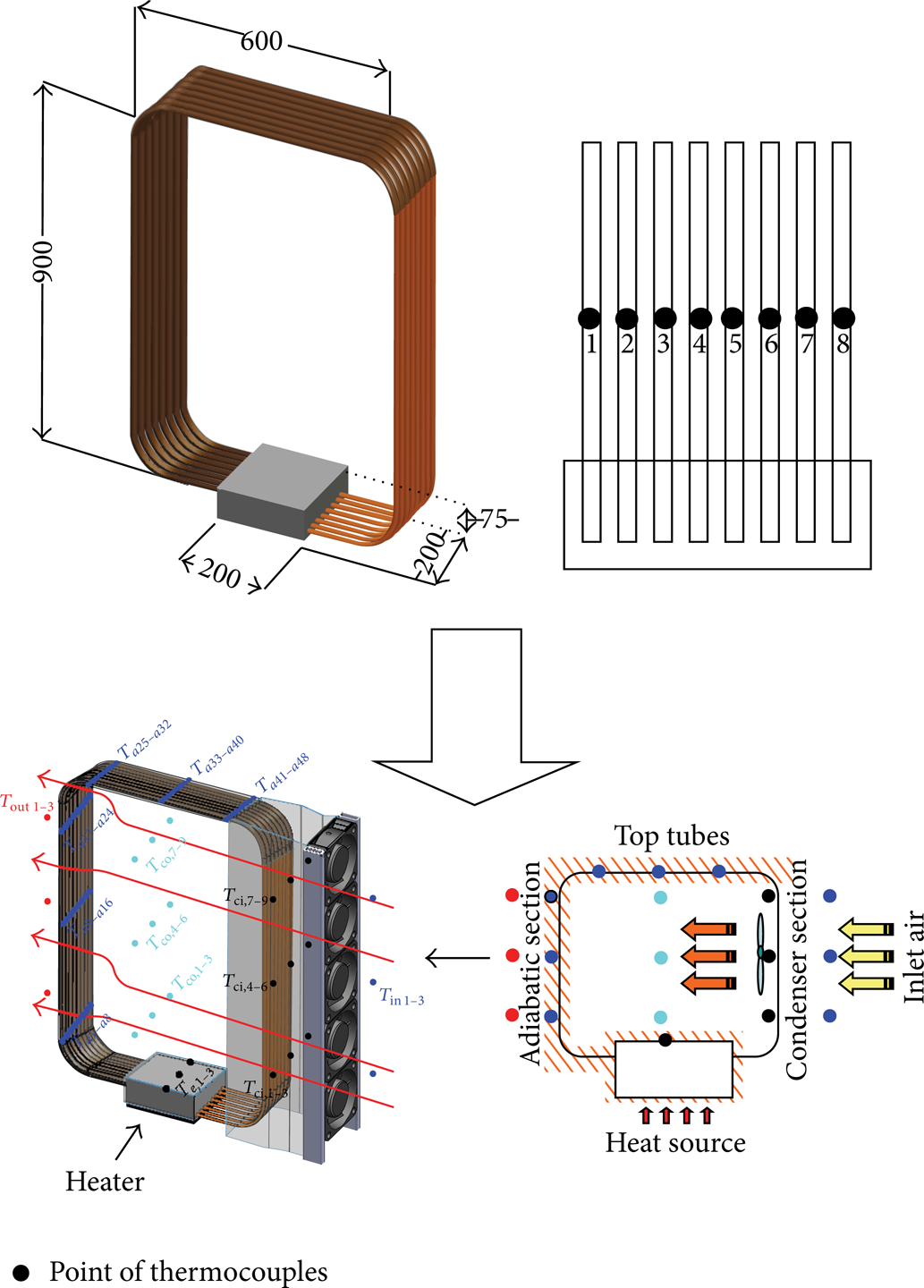
Schematic diagram of experimental apparatus and point of thermocouples setting for saving data.
A one-dimensionless quantity is a quantity without an associated physical dimension. It can be obtained from the relationship between a body and a focused property for a particular phenomenon which occurs inside an LTVC.
The volume dimension characteristic, the aspect ratio, represents the distance and volume of the physical motion for a working fluid (liquid and vapour). When the aspect ratio increased, the heat transfer rate rose phenomenally [1, 13, 14]. Thus, the larger aspect ratio leads to pool boiling, which occurs with the highest heat transfer rate. However, the phenomenon has approached an inside of confine channel within lower heat transfer rate [12, 15–17]. The aspect ratio can be defined with the following equation:

2.3. Heat Transfer Analysis
Seventy-five points of thermocouple Type K (OMEGA with ± 0.1°C accuracy) were installed along with a data logger and attached to the LTVC (Yokogawa DX200 with ± 0.1°C accuracy, 80 channels input, and −200°C to 1,100°C measurement temperature ranges). Three points were attached at the inlet heating area of the evaporator section. The heat input at evaporator section was used via heater (600, 900, and 1,200 W) with dimension 200 × 200 × 5 mm (W × L × H). Twenty-four points were attached at the inlet/outlet area of the cooling of the condenser section. The fresh air inlet was maintained at 25°C. Forty-eight points were also attached at thermosyphon surface of the adiabatic section. The tubes were covered with insulation.
In general possible heat transfer rate (QPossible) is

The hypotheses of QLoss are as follows.
Four walls of chamber were vertical plate with uniform walls.
The upper chamber was the horizontal plate of the hot surface fating up.
The bottom chamber was radiation and conduction transfer.
Thus, three hypotheses were important for boiling of working fluids. The boiling phenomenon controlled the vapour flow rate inside each loop thermosyphon.
The QLoss findings from temperature were measured at the chamber as follows [13, 18]:

During the experiments, the variable parameter was controlled in order to calculate the heat transfer rate characteristics of the LTVC using the convection heat transfer mode according to Incropera and Dewitt [18]. The following equations were used to calculate the experiment of heat transfer rate (QExperiment) in (4). Then QExperiment was used for error analysis of heat transfer (QError analysis) in (6) as recently suggested by Parametthanuwat et al. [18, 19] as follows:

Thus,

Then,

Loops thermosyphon were installed in the vapour chamber. The performance of LTVC is represented by its relative thermal efficiency (R T ) in (7). The relative thermal efficiency is defined as the ratio of heat transfer rate of LTVC to the maximum possible heat of the actual transfer. Therefore,

The relative thermal efficiency plays a role in heat transfer enchantment of LTVC. It is higher in the vapour than in the liquid. The vapour chamber is expected to improve the vapour flow rate. Consequently, the LTVC shows that the relative thermal efficiency closely effectiveness of theorem. Thus, the relative thermal efficiency depends on three hypotheses of QLoss that affect vapour flow rate in the eight-loop thermosyphon.
The variables used in the experiment are shown in Table 1; they formulated the heat transfer rate characteristics of the LTVC.
The parameters of loop thermosyphons with the vapour chamber (LTVC) variable of the study.

3. Results and Discussion
3.1. The Results of Temperature Distribution
Figures 3(a) and 3(b) show the adiabatic temperature at the upper part and the side of the LTVC at different times. It was found that the temperature distribution around the upper part and the side of the LTVC showed a positive trend. The maximum temperature difference of both ovens was ± 3°C at each loop with distilled water as a working fluid with a filling ratio of 40% and heat input at 900 W. Consequently, the LTVC helped to regulate the temperature distribution regularly for each loop. In addition, start up to 400'sec shows transient transfer then 400'sec to end shows steady state. Accordingly, the transient transfer that occurred from the unequally filled working fluid flow in the eight loops of the thermosyphon results in the nonuniform distribution of temperature. Nevertheless, the experiment found that the steady state could be explained in vapour flow rate; the vapour flow rate was equally filled up in the eight loops of the thermosyphon in order to distribute the temperature. Moreover, the vapour flow rate helped thermal distribution and gave a good similarly tend of temperature.
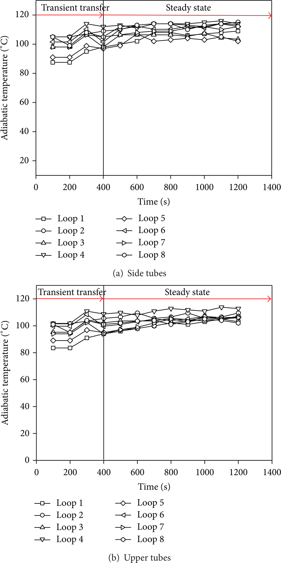
Relationship between time and adiabatic section temperature.
3.2. Effect of Velocity and Relative Thermal Efficiency
The relationship between the air velocity and relative thermal efficiency of LTVC with an aspect ratio of 1.5 and a filling ratio of 60% is shown in Figure 4. The relative thermal efficiency decreased with the air velocity. Considering the case where the working fluid was ethanol with a heat input of 1,200 W with 0.5 m/s, the resulting relative thermal efficiency was 0.76. The increase of maximum relative thermal efficiency with decrease of air velocity can be attributed to the increase in operating temperature. As the operating temperature increased, the system approached pool boiling [15, 20]. The heat transfer rate was increased twice and showed a different temperature [19]. Accordingly, the lower air velocity caused sufficient difference of temperature (ΔT) causing the relative thermal efficiency to be higher and further than the higher air velocity. When the air velocity was increased, the amount of air in the condenser section also increased which reduced the relative thermal efficiency. This observation agrees with (4) and (7).

Relationship between heat input and relative thermal efficiency.
3.3. Effect of Filling Ratio on the Rating of the Heat Transfer
The result of the filling ratio's effect on rating of the heat transfer of the LTVC was R-11, as shown in Figure 5. Moreover, the filling ratio of 60% at a heating of 1,200 W and an aspect ratio of 2 yielded a relative thermal efficiency greater than with other study conditions. It was found that the maximum relative thermal efficiency occurred at an air velocity of 0.5 m/s when the rating of the heat transfer was 0.97. Certainly, it can be seen that while the air velocity was increased from 0.5 to 1.5 m/s, the rating of the heat transfer slightly decreased. The filling ratios of 20% and 40% presumably caused drying out of the chamber section [5, 19, 21]. Moreover, the film critical thickness was strongly dependent on the thermal resistance. For high values of film thickness, thermal resistance increases with a decrease in the heat transfer rate [15]. On the other hand, the lower values of the film thickness caused reduction of thermal resistance occurring burnout's effect to non-heat transfer rate in the LTVC [22–24]. Therefore, the filling ratio of 60% was the most favorable one to use.

Relationship between filling and relative thermal efficiency.
3.4. Effect of Aspect Ratio on the Relative Thermal Efficiency
The results of the aspect ratio which affected the rating of the heat transfer of a LTVC that was filled with R-11, ethanol, and water are shown in Figure 6. The experimental results clearly show the effects of the aspect ratio on the rating of the heat transfer. When comparing the aspect ratio using different working fluids, it was seen that the R-11 showed that the relative thermal efficiency was higher than with other working fluids. This section shows the results of the aspect ratios of 1.5, 2, and 2.5 on the heat input at 1,200 W, velocities of 0.5, 1, and 1.5 m/s, and at a filling ratio of 60% with respect to the vapour chamber volume. It was found that the maximum rating of the heat transfer was 1 of R-11 at a velocity of 0.5 m/s and an aspect ratio of 2.5 in the study conditions.

Relationship between aspect ratio and relative thermal efficiency.
Accordingly, it can be seen that while the aspect ratio increased from 1.5 to 2.5, the heat transfer rate only slightly rised. Therefore only the larger aspect ratio approached pool boiling [15, 25]. The pool boiling only occurred when the high heat transfer rate was reached. On the other hand, the boiling phenomenon approached the inside of the confined channel which had a lower heat transfer rate [15, 26]. Moreover, as the area of the vapour chamber increased the surface area of the working fluid, the lead time period (for the vapour to be uniformly dispersed) improved. It can be predicted that the system probably returned to the evaporator section due to its high condensation rate. This ensures an ample amount of working fluid for boiling and phase transition [24].
4. Conclusions
A LTVC was applied from traditional thermosyphon. Experiments were conducted on the vapour chamber using various sizes, heat inputs, and air velocity coolants to study effect of various parameters on heat transfer rate and relative thermal efficiency. It was found that the LTVC gave the best of relative thermal efficiency of 1 at R-11, a filling ratio of 60%, a velocity of 0.5 m/s, and an aspect ratio of 2.5 under the study conditions. However, there were several physical properties proposed to explain the enhancement rating of the heat transfer as follows.
The larger vapour chamber of the LTVC led to pool boiling, thus increasing the heat transfer rate.
The air velocity was increased; the amount of air over condenser section also increased which reduced the relative thermal efficiency.
The operating temperature had no effect on relative thermal efficiency but the properties of working fluid affected relative thermal efficiency.
The optimum filling ratio when adding the working fluid to the LTVC was 60% when the critical film thickness occurred and the highest heat transfer rate was achieved.
This result confirms that the proposed delimitation of the study of the LTVC is a novel study. However, the thermal performance analysis is similar to the limit of general heat pipe and normal heat flux. As expected, the limits of the LTVC may depend on the number of loops and the volume of the working fluid.
The vapour chamber area generates vapour (ACh) equal to the total area of the loop thermosyphon. Then, the vapour has access to the condenser section (AC, inlet). Thus, the proportion of ACh:AC, inlet had an effect on the viscosity and velocity of the vapour movement. If the ACh:AC, inlet was not optimized, ACh:AC, inlet had an effect on dryout or burnout, causing to block liquid in vapour chamber.
The minimum volume of the working fluid had an effect on how rapidly the liquid phase changed to vapour. Moreover, working fluid produces an effect on the vapour phase making the liquid unable or inadequate to return back to the chamber. The limit of the LTVC was intended to provide a background for discussion of the results, as shown in the next study.
Footnotes
Nomenclature
Conflict of Interests
The authors declare that there is no conflict of interests regarding the publication of this paper.
Acknowledgments
This research has been supported generously by the Heat-Pipe and Thermal Tools Design Research Unit, Faculty of Engineering, Mahasarakham University, Thailand, and the Faculty of Industrial and Technology Management, King Mongkut's University of Technology North Bangkok, Thailand.