
Abstract
In microelectrical discharge machining (micro-EDM) milling process, due to the unavoidability of electrode wear, selection of electrode with high electrical erosion resistance and accurate electrode compensation is entitled to be conducted to ensure high precision and high quality. The RVWR is used as criterion for electrode wear characteristics and is fundamental to achieve accurate electrode compensation; however, it is hardly measured accurately with conventional methods. In this paper, firstly, the error of RVWR measured by conventional measurement method is analyzed. Thereafter, for accurately measuring RVWR, a new measurement method is proposed based on electrical debris composition analysis. The RVWR of widely used tungsten, molybdenum, and copper electrode in machining different materials is measured, respectively, and the optimum electrode is selected based on the measuring results. Finally, microgrooves on different materials are machined with tungsten electrode, and the experiment results show that the microstructures have good bottom surface profiles, which indicates that the proposed method is effective to precisely measure the RVWR and guarantee accurate electrode compensation in micro-EDM process.
1. Introduction
With the continuous development of technologies in various industrial fields quite recently, the demands on product miniaturization are getting increasingly intensive, which stimulates the innovation on new micromachining and precision machining approaches with high machining efficiency and quality. Microelectrical discharge machining (micro-EDM), because of such advantages as contact-less process, no cutting force, low cost, and wide materials suit to fabricate, has been widely applied in the manufacturing of geometrically complex and hard material microstructures. At present, it has been recognized as one of the most valuable techniques for micromachining [1–3].
In three-dimensional (3D) microcavities machining, the fabrication of complex shaped microelectrodes used in die-sinking micro-EDM is very difficult and costly [4, 5]. With the development of wire electrical discharge grinding (WEDG) technology [6], the micro-EDM milling method with simple-shaped electrode (usually with cylindrical section) is widely adopted [7, 8]. Nevertheless, owing to the principle of EDM, the occurrence of electrode wear is inevitable. And it is much more severe in micro-EDM milling process, due to certain characters of micro-EDM, such as microenergy and high frequency discharge, microsized electrode, large depth-to-width ratio, and hostile processing condition. Insufficient depth of a microgroove/cavity and geometrical inaccuracy of a microstructure are caused by electrode wears in micro-EDM milling process. Thus, in order to enhance machining precision and quality, accurate and effective electrode compensation is entitled to be conducted in micro-EDM milling processes.
Many methods have been presented in solving the problem of electrode wear, such as optimum electrode material selecting and various types of electrode compensation method. Uhlmann and Roehner [9] conducted extensive experimental investigations aiming to decrease the wear of tool electrodes by using boron doped CVD-diamond (B-CVD) and polycrystalline diamond (PCD). Tsai and Masuzawa [10] studied the effects of thermal properties on electrode wear and pointed out that the boiling point of the electrode material plays an important role in the wear mechanism of micro-EDM. Yu et al. [7] and Rajurkar and Yu [11] proposed a uniform wear method (UWM) by scanning the workpiece layer by layer and integrated the electrode compensation and path planning to CAD/CAM system of micro-EDM. Pei et al. [12, 13] presented a fix-length electrode compensation method and studied the effects of RVWR on microgrooves by simulation in micro-EDM milling process. Wang et al. [14] studied the layer-by-layer processing technology of micro-EDM milling process. Bleys et al. [15] presented real-time tool wear sensing and compensation in layer-by-layer EDM milling based on discharge pulse evaluation to estimate electrode wear online with a mathematical model of the sparking frequency. Aligiri et al. [16] also presented a compensation method to estimate material removal volume by counting the number of discharge pulses. To improve machining efficiency, Yan et al. [17] proposed an electrode wear compensation method in micro-EDM using an optical measurement of the tool electrode. However, the proposed compensation approaches [15–17] heavily rely on sophisticated monitoring systems or optical measure systems, which limit their practical applications.
In micro-EDM milling process, the relative volume wear ratio (RVWR) is a vital parameter, which not only is used as criterion for selecting electrode but also is fundamental to achieve accurate compensation in above compensation methods. However, owing to tiny removal of workpiece and electrode, the RVWR can be hardly measured accurately with conventional methods. At present, the RVWR can be measured roughly by machining microholes method or machining microgrooves method, and by calculating the worn volumes of electrodes and workpieces, and the volume wear ratio is obtained as the quotient of them. Although the conventional methods are easy to be conducted, the measurement errors of the geometrical sizes are usually big. Therefore, further experiential works have to be conducted to obtain a relative accurate value, which evidently restrict their practical applicability.
In this paper, the RVWR of machining T2 copper using tungsten electrode is firstly measured by machining microholes method and microgroove machining experiments are conducted to analyze the error of RVWR obtained by conventional method. Then, a new measurement method is presented based on electrical debris composition analysis. Discharge processes on different materials with tungsten, molybdenum, and copper electrode are conducted, and the corresponding RVWR is measured by the proposed method. Finally, the optimum electrode in machining the three kinds of materials is selected according to the measurement results, and microgrooves on these three kinds of materials are machined with tungsten electrode and the measured RVWR.
2. The RVWR Measured by Machining Microholes Method
The RVWR is a vital parameter to conduct accurately electrode compensation and can be used as criterion for electrode wear characteristics which is a reference for selecting an electrode with high electrical erosion resistance. Firstly, the error of the RVWR measured by conventional method is analyzed according to the effects of that on microgrooves.
In order to analyze the effects of RVWR on microgrooves machining, the model of large monolayer thickness and fix-length compensation method [18] are adopted in this paper. The mathematical model is shown in (1). Consider

where L is fixed compensation length; le is compensation accuracy; d is the diameter of electrode; K v is correction volume coefficient which is obtained by extensive experiments; δ is side machining gap; lw is the machining depth (or the layer thickness); γ is the RVWR. Evidently, when the compensation accuracy le, the machining depth lw, and the correction area coefficient K v are set beforehand, fixed compensation distance L is a function of RVWR γ and the actual bottom surface profile is built based on γ. Therefore, the error of γ cause the error of L, which results in overcompensation or undercompensation of microgrooves.
2.1. Experimental Condition
Machining tests are conducted on our self-established high-precision micro-EDM system, as shown in Figure 1, which has a three-axis linkage function with travel of 110 mm(X) × 110 mm(Y) × 120 mm(Z), z-axis linear motor worktable with positioning accuracy of 2 μm, an X-Y axis alternating current servomotor worktable with positioning accuracy of 1.5 μm, 0.1 μm resolution cooperated with the Renishaw grating, a high-speed rotating spindle, a switch tube microenergy resistor-capacitor (RC) pulse power supply, and a self-established NC milling system. Moreover, KEYENCE VHX-600 digital microscope with 3D geometry measuring function is employed to measure the size and shape of microstructures machined in this paper.

The photograph of the experimental platform.
The electrode and workpiece materials are listed as follows: copper, tungsten, and molybdenum with diameter 100 μm are selected as electrode and 3003 aluminium alloy, #45 steel, and T2 copper are used as workpiece. Moreover, the processing parameters setup is shown in Table 1.
Discharge parameters setup.

The dielectric strength of deionized water is 16 MΩ·cm.
2.2. Error Analysis of the RVWR Measured by Conventional Method
To validate the effects of RVWR on microgrooves machining, microgrooves on T2 copper materials are machined using tungsten electrode with λ obtained by microgrooves machining method. The correlation parameters are shown in Table 2.
Compensation parameters setup.
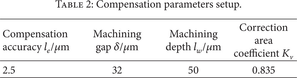
Where K v = K s ·K d , K c is area coefficient and K d is depth coefficient, and they are estimated by extensive experiments according to [18]. The RVWR of machining T2 copper using tungsten electrode is first measured by machining microholes method, with specific procedure as follows.
Machining n micro-through-holes continuously with the electrode diameter of d.
Measuring these through-holes’ radius of entrance and exit, which are indicated as r1i and r2i, respectively.
Measuring the electrode wear length l with machine tool's electric contacting function.
Calculating the RVWR λ by (2).
Consider
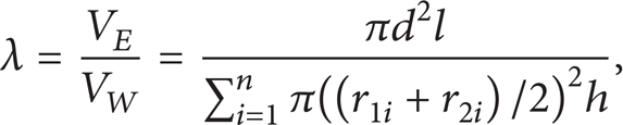
where V E is the wear volume of the electrode; V W is the wear volume of workpiece; h is the depth of the through-holes.
In this paper, a tungsten electrode with diameter 100 μm is used to machine 13 through-holes on 0.3 mm thickness T2 copper workpiece. Consequently, the calculated value of RVWR is 0.028.
Under the condition λ1 = 0.028, an 8 mm long microgroove is machined based on large monolayer and fix-length compensation method. The micrograph and depth variation of microgroove are shown in Figure 2.

Micrographs of microchannel on copper with overcompensation.
As shown in Figure 2, the depth of microgroove increases along with the machining distances. When the machining distance is about 2 mm, the depth reaches about 61 μm which is about 20% deeper than designed. It is caused by the problem that the RVWR measured by microholes method is greater than the actual value. Obviously, the error of the RVWR measured by machining microholes method is big, and the reasons are analyzed as follows.
Electrode end wear is considered merely in electrode length measurement. However, electrode side wear is serious in machining microholes method. The measurement errors of the geometrical sizes are usually large.
There are nonignorable errors in electrode wear length measured by electrical contacting function, due to the measuring principle and the repositioning precision of machine tools.
The direct effect of RVWR on microgroove machining is the variation of depth. The microgroove is machined with overcut, when λ is greater than the actual value; conversely, the microgroove is machined with undercut, when λ is less than the actual value [16]. Thus, the microgroove is machined precisely only when λ is equal to the actual value, and the RVWR can be validated according to the accuracy of depth of machined microgroove. In addition, the RVWR measured by machining microholes method is not accurate, and experimental correction by extensive experiments has to be conducted to achieve a relative accurate value. Therefore, a new RVWR measurement method is proposed in Section 2.
3. A New Measurement Method of RVWR Based on Electrical Debris Composition Analysis
In micro-EDM process, electrical debris, which is composed of electrode, workpiece, and working medium elements, is thrown into the working fluid, forming globular microparticles. Only a tiny part of electrical debris adheres to the surface of electrode and workpiece, forming cladding layer [19, 20]. Moreover, despite whatever chemical reaction (such as oxidation and carbonization) during machining process, the total amount of metallic elements in electrical debris are always equal to that in the dissipative electrode and workpiece according to the law of conservation of mass; that is, the quality ratio of electrode element and workpiece element in electrical debris is equal to that of the dissipative electrode and workpiece. Once the proportions of major elements in the debris are measured, the RVWR can be calculated based on the composition and density of electrode and workpiece. Therefore, a new measurement method of RVWR based on debris composition analysis is proposed in this paper. The major measurement steps of RVWR based on debris composition analysis are as follows.
The content of major components of the chosen electrode and workpiece is firstly measured.
Machining experiment with the chosen electrode and workpiece material is conducted for a period of time.
The working fluid is carefully filtered to collect the electrical debris.
The collected electrical debris is put into the vacuum drying oven and then dried for about 2 hours.
The proportion of each component of electrode and workpiece materials in the prepared electrical debris powder is measured. Moreover, the measurements are repeated several times (3 times) and averaged, considering that the elements contented in the debris may not be homogeneous.
The quality wear ratio according to the composition of electrode and workpiece is calculated.
The RVWR is finally obtained according to the densities of electrode and workpiece.
4. RVWR Measurement of Micro-EDM Process
4.1. Material Composition and Measuring Instrument
In this paper, using the parameters of Table 1, discharge machining processes on 3003 aluminium alloy, #45 steel, and T2 copper materials are firstly machined by tungsten electrode, respectively, and the corresponding electrical debris is gathered and dried to make specimen. Moreover, EPMA-1600 electron probe microanalyzer (Shimadzu Corporation), as shown in Figure 3, is employed to gain the mass fraction, and then the RVWR is calculated according to the density of electrode and workpiece. In addition, to select the optimum electrode in machining these three materials, the same experiments are repeated by molybdenum and copper electrode.
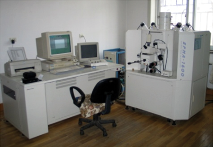
The photograph of EPMA-1600.
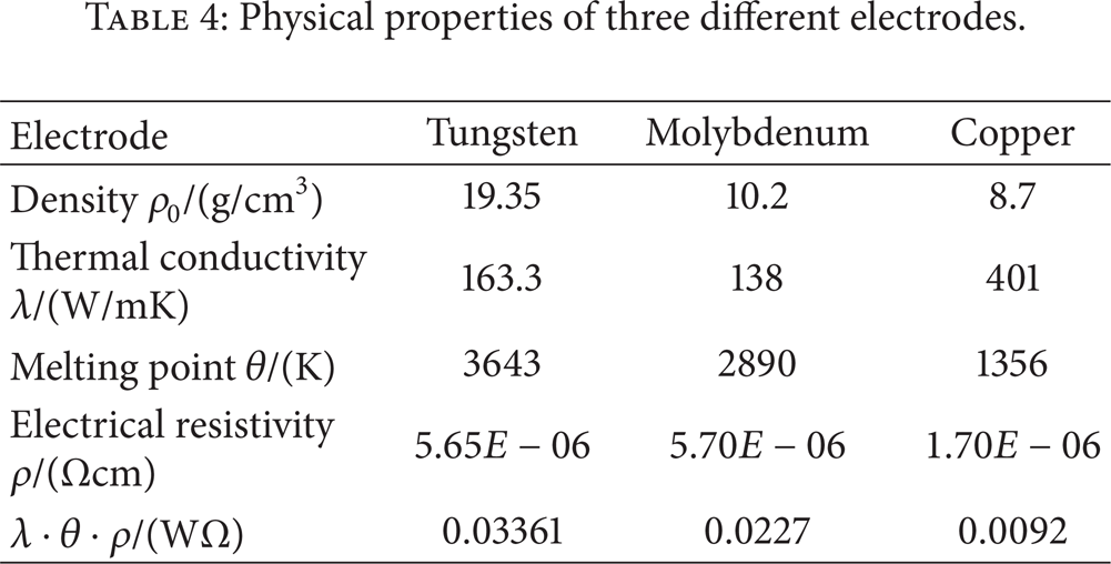
The composition and density of three kinds of workpiece materials are shown in Table 3. According to the λ·θ·ρ theory [21], the thermal conductivity, melting point, and electrical resistivity are the main factors which influence the corrosion stability of electrode. The physical properties of electrode materials are shown in Table 4.
Composition and density of three workpiece materials.

Physical properties of three different electrodes.
4.2. RVWR Measurement
4.2.1. Tungsten Electrode
The major element contents of the electrical debris are shown in Figure 4 and the detailed analysis results of the electrical debris are shown in Table 5, when tungsten electrode is used to machine 3003 aluminium alloy, T2 copper, and #45 steel. As shown in Table 5, the tungsten electrode wear is very small, when it is used to machine the three kinds of workpiece materials.
Results of discharge debris composition analysis.


Composition of discharge debris produced by tungsten electrode machining different workpieces.
4.2.2. Molybdenum Electrode
The major element contents of the electrical debris are shown in Figure 5 and the detailed analysis results of the electrical debris are shown in Table 6, when molybdenum electrode is used to machine 3003 aluminium alloy, T2 copper, and #45 steel. As shown in Table 6, the wear of molybdenum electrode machining T2 copper is very small and even less than that of tungsten electrode; however, the wear of molybdenum electrode machining aluminium alloy is much larger than that of tungsten electrode. The molybdenum electrode wear in machining aluminium alloy is about 9 times greater than that in machining T2 copper.
Results of discharge debris composition analysis.


Composition of discharge debris produced by molybdenum electrode machining different workpieces.
4.2.3. Copper Electrode
The RVWR cannot be measured, as the major element, Cu, is simultaneously contained in electrode and workpiece, when T2 copper is machined by copper electrode.
The major element contents of the electrical debris are shown in Figure 6 and the detailed analysis results of the electrical debris are shown in Table 7, when copper electrode is used to machine 3003 aluminium alloy and #45 steel. As shown in Table 7, the wear of copper electrode in machining these two kinds of workpiece materials is larger than that of tungsten electrode, and the copper electrode wear in machining #45 steel is about 6 times greater than that in machining aluminium alloy.
Results of discharge debris composition analysis.


Composition of discharge debris produced by copper electrode machining different workpieces.
When the major elements of electrical debris are simultaneously contained in electrode and workpiece, by the proposed method, the RVWR cannot be measured accurately. However, in practical applications, it is uncommon that the major elements are simultaneously contained in electrode and workpiece, for instance, copper electrode used to machine copper alloy materials is scarcely adopted. Therefore, the proposed method is an effective and accurate method to measure the RVWR of most electrodes in machining different workpieces under complex processing condition.
4.3. Experimental Results Analysis
In micro-EDM milling process, in order to avoid frequent compensation and achieve better size and shape accuracy, it is desirable that the electrode with high electrical erosion resistance can be employed effectively, which means that the machined distance L should be as long as possible in the same compensation accuracy le. In this case, the length of the electrode decreases most slowly and the bottom surface profile can be a gentle slope. Therefore, it is an important way to enhance the processing quality and processing efficiency by selecting electrode reasonably in micro-EDM milling process.
In this paper, three kinds of electrode materials, tungsten, molybdenum, and copper, are selected to machine microgrooves on different workpiece materials, and the corresponding RVWR is measured accurately by the proposed method, which provides a reliable basis for both selecting electrode materials reasonably and exactly conducting compensation. The RVWR comparison charts of machining the different materials using the three kinds of electrode are shown in Figure 7.
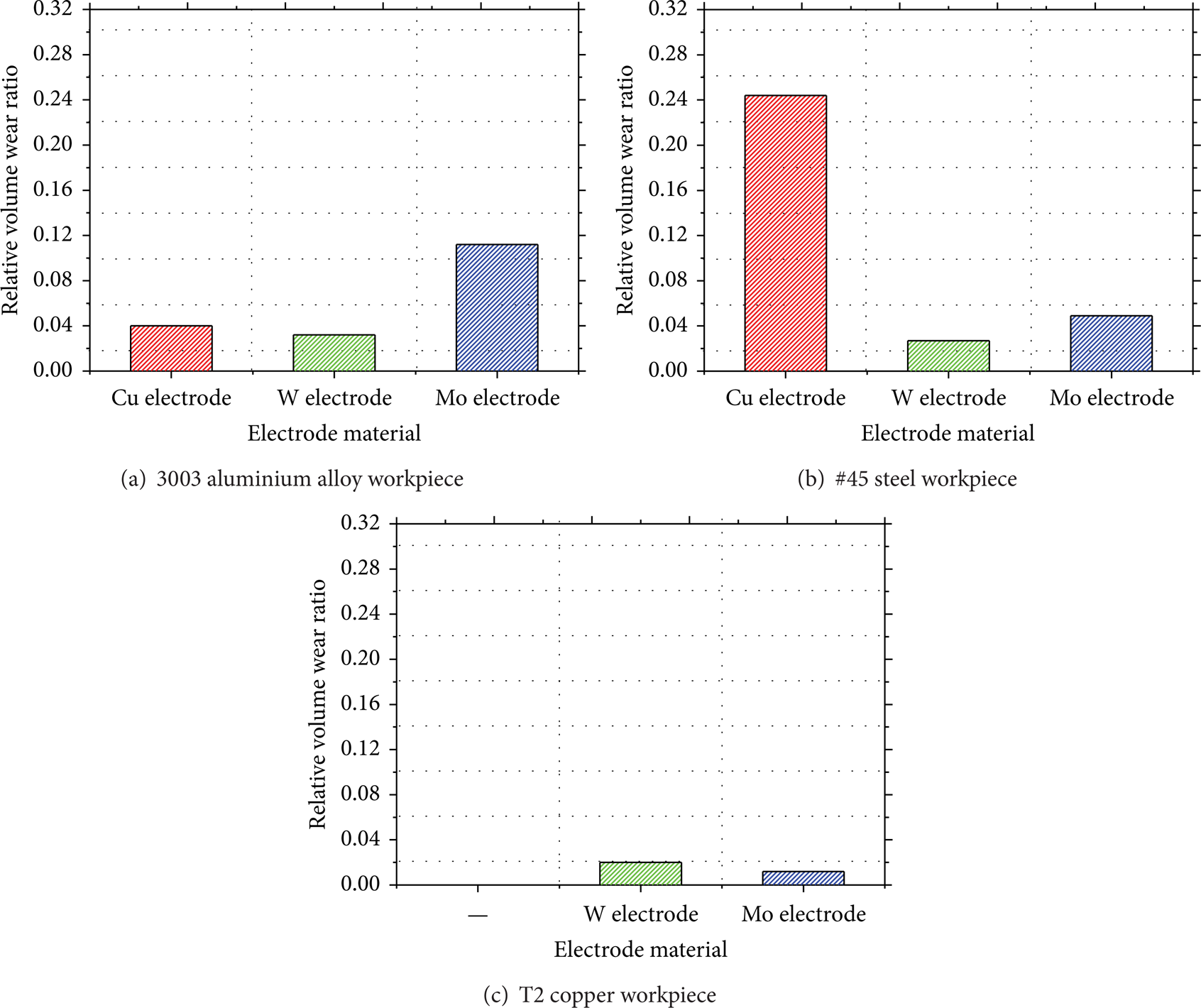
RVWR of different electrodes in machining different workpieces.
As shown in Figure 7, from the perspective of reducing electrode wear, the following rules should be followed: tungsten electrode is prior selected, when #45 steel and aluminium alloy materials are machined; owing to tiny electrode wear, when T2 copper is machined, either tungsten electrode or molybdenum electrode can be selected. In other words, the tungsten electrode, which has the highest value of λ·θ·ρ [21], can be used to machine microgrooves on these three materials with smaller electrode wear.
5. Microgrooves Machining Experiments
The proposed method provides a reliable basis for both selecting electrode materials reasonably and exactly conducting compensation with the measured RVWR. In this paper, tungsten electrode as the optimum electrode is selected to machine microstructures on copper, aluminium alloy, and #45 steel, due to its high electrical erosion resistance in machining the three kinds of workpiece materials. The RVWR of tungsten electrode machining T2 copper, aluminium alloy, and #45 steel is 0.020, 0.032, and 0.027, respectively. Moreover, microgrooves on these three kinds of materials are machined based on large monolayer thickness and fix-length compensation method, as shown in Figures 8–10.
Square wave microgroove on T2 copper workpiece.
Micrograph of short microgroove on aluminium alloy.
Curve microgrooves on #45 steel.
5.1. Experiments on T2 Copper
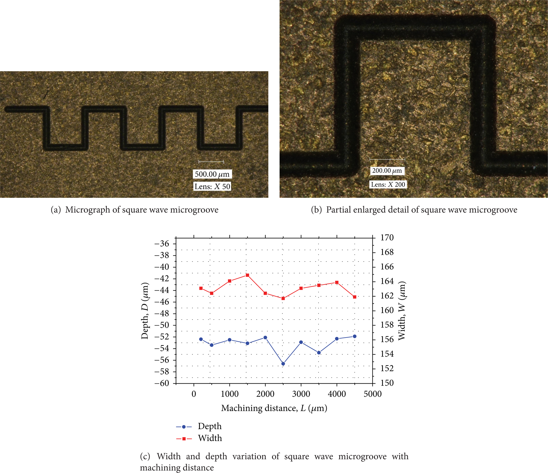
A square wave microgroove on T2 copper is machined by the parameters listed in Table 2. The micrograph of microgroove is shown in Figure 8(a), and its partial enlarged detail is shown in Figure 8(b), and its width and depth variation with the machining distance is shown in Figure 8(c). As shown in Figure 8, the maximum width and depth variations on the overall length are 3.1 μm and 4.7 μm, respectively, and the microgroove has good uniformity in width and depth.
5.2. Experiments on Aluminium Alloy
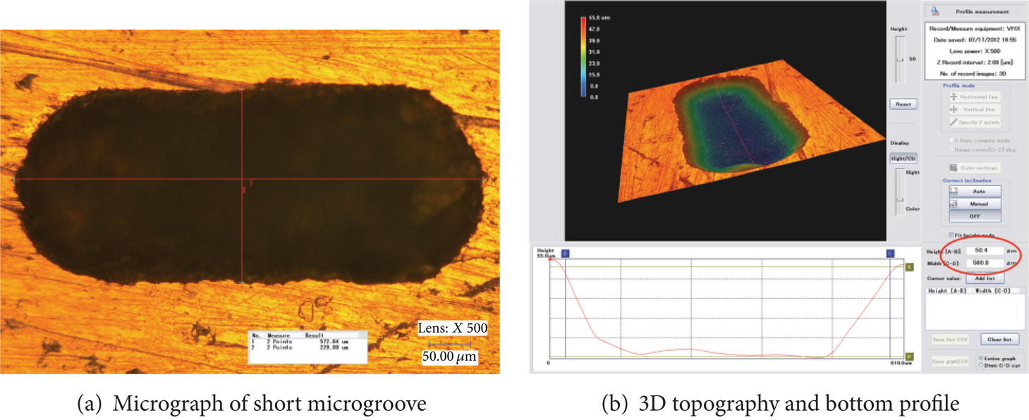
A short microgroove with 600 μm length on aluminium alloy is machined by the parameters listed in Table 8. The micrograph of short microgroove is shown in Figure 9(a) and its 3D topography with bottom profile is shown in Figure 9(b). Figure 9 indicates that the maximum depth of the microgroove is 50.4 μm, and the microgroove has good bottom surface profiles.
Compensation parameters.

5.3. Experiments on #45 Steel
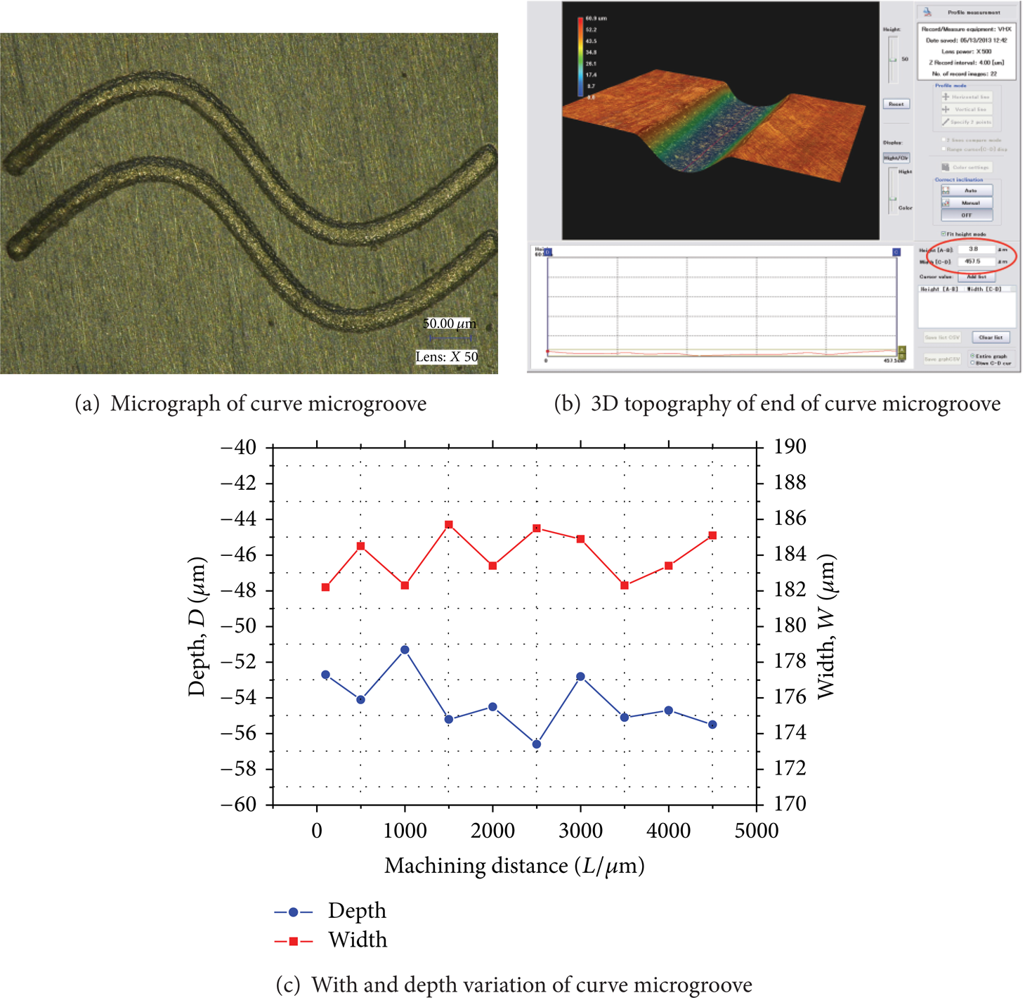
Two curve microgrooves are machined on #45 steel by the parameters listed in Table 9. The micrograph of machined curve microgrooves is shown in Figure 10(a), and its 3D topography of upper groove is shown in Figure 10(b), and width and depth variation with machining distance is shown in Figure 10(c). As shown in Figure 10, depth variation on about 500 μm long range is 3.8 μm, and the maximum width and depth variations on the overall length are 3.5 μm and 5.3 μm, respectively, and the curve microgroove has good bottom surface profiles.
Compensation parameters.

As shown in Figures 8–10, the microgrooves and structure have good bottom surface profiles, which indicate that the proposed method in the paper can effectively and accurately measure the RVWR of most electrodes in machining different materials.
6. Conclusion
In this paper, in microgrooves EDM, experimental results on electrode compensation show that the RVWR obtained by conventional measurement method is inaccurate and can result in variation of groove depth. Then, based on electrical debris composition analysis, a new RVWR measurement method is proposed, which can be applicable to different electrodes machining different workpiece materials without simplifying the processing environment. The RVWR of machining T2 copper, aluminum alloy, and #45 steel using the electrodes of tungsten, molybdenum, and copper are measured. Selection of electrode with high electrical erosion resistance and accurate electrode compensation experiments are conducted according to the measuring results. Experiments on microgrooves show that the machined microstructures have good bottom surface profiles, which indicates that the proposed method is an effective way to accurately measure the RVWR of most electrodes in machining different workpiece materials. This research conclusion can be adopted as a basis in selecting electrode material reasonably and ensuring the accurate compensation in micro-EDM. Further study is suggested to focus on measuring the RVWR of more electrode materials and workpiece materials with plenty of experiments and establishing a database of widely used electrodes in machining different workpiece materials, which can provide an important reference to practical applications.
Conflict of Interests
The authors declare that there is no conflict of interests regarding the publication of this paper.
Footnotes
Acknowledgments
This paper is supported by the National Natural Science Foundation of China (Grant no. 51005036).