
Abstract
The paper deals with the process of 3D digitization as a tool for increasing production efficiency of complex shaped parts. Utilizes the concept of reverse engineering and new the model of NC program generation STEP-NC, for the of templates production for winding the stator coil of electromotors that is for electric household appliances. The manual production of prototype was substituted by manufacturing with NC machines. A 3D scanner was used for data digitizing, CAD/CAM system Pro/Engineering was used for NC program generation, and 3D measuring equipment was used for verification of new produced parts. The company estimated that only due to the implementation of STEP NC standard into production process it was allowed to read the 3D geometry of the product without problems. It helps the workshop to shorten the time needed for part production by about 30%.
1. Introduction
The only way for companies to survive and prosper is their ability to achieve a good indicator of profit and to respond quickly to market demands. In the mechanical engineering industry and manufacturing technologies holds much more. Being faster to market while increasing quality, this is a crucial competitive advantage of successful business future, which raises the need to address complex problems in all phases of development and production of selected products with the utilization of available technical, information, and automation systems. The choice of technology is influenced not only by production costs, but it is also influenced by shape of the part, the request for material of product, and manufacturing conditions inside the plant. The development of industry has brought a new way of thinking to designers in which simple geometric shaped parts are connected to groups and these are substituted by one complex shaped part. The choice of production technology in this case can have a major impact not only on the costs of production but also the main period of production. The same product from the same material can be produced by various technological manners, including combinations. At the design stage of a new product, in the phase of prototype preparation, a 3D model is created at first, and then the analyses and simulations of the production process are conducted. After fault elimination, drawing and technological documentation are completed and only on this basis is the component produced. The problems occur when the actual component exists; for example, in the form of a hand-made model, the complex shape and the dimensional or geometrical characteristics are not known. The production of other (exactly the same) components is in this case problematic, especially where a mass production is concerned. This problem can be solved by means of 3D digitization within the process of Reverse engineering. The digitization of real objects is possible due to scanning equipment which enables the conversion of real three dimensional objects into a digital form.
2. State of the Art: Literature Review
Not only is the technologist's work based on the requirements of the product (design, configuration, quality, accuracy, etc.), but also it has to reflect on the appropriate use and utilization of the equipment, as well as labour and working subjects. It is realized by the use of capabilities, technical characteristics of speed, and versatility of machines in working equipment; similarly it is realized by the using materials at the working objects so as to reduce the proportion of material losses and waste, while increasing the quantity per unit weight, area, or volume of the basic material. Labour power is the use of the skills and experiences as well as mental and physiological abilities of man. In other words, the level of technology can be evaluated according to the use of all elements of production processes to improve the quality and functional properties of the elements as are products or performances. The technology determines not only the utilization of production equipment, but also the working mode of action items with the goal to create new product. The biggest challenge is the selection of efficient technology, which allows the lowest cost to achieve the best quality and functional properties of products.
The production process is realized on the bases of manufacturing process plans, creation of which is conditional to the existence and interaction of several factors. The most important of them and their aspects are as follows [1]:
product (the design concept, the technological approach, the dimensional tolerances, tolerances of shapes and position, the relationship of design and technological bases, productivity, size of the batch, and the manipulability),
material and raw product (workability by individual technologies, operating allowances),
machines and production equipment (precision, technological options, and productivity),
technology (availability, required accuracy, the desired roughness, and material effect),
personnel (qualification and expertise),
energy (type, method of transfer, amount),
organization (time and space structure).
The considerable complexity of the factors listed above influences the decision which of the technologies, rows, production equipment, parameters, and so forth, will be used at part manufacturing.
Development of manufactured parts, increasing demands for quality, shortening of delivery deadlines, increasing cost of human labour, rapidly changing manufacturing conditions, these are only several reasons that force manufacturers to use NC machines for various technological operations. For maximum utilization of NC machines the CAD/CAM systems employment has substantial importance. CAD/CAM system allows you to comprehensively solve the development-design and production phase of a new product [2, 3]. Integrating CAD and CAM modules into a single unit can be preserved on a single data platform, which ensures a smooth transfer of information. The latest CAM software for PC (personal computer) provides many automated features that make NC programming largely a push-button affair, regardless of how simple or complex the workpiece may be.
Up to now, the programming of parts for NC machine tools was normally done by means of standard ISO 6983. This standard dates back to the time of punched cards and does not cover the demands of modern technology. Therefore a new STEP-compliant programming interface which is based on an object-oriented data model (ISO 14649) was developed. This is a radically different approach to CNC programming. The concept behind STEP NC is simple. It enables a product model database to serve as direct input to a CNC machine tool, no separate files of tool paths, no G or M codes, and no postprocessors. ISO 14649 is proposed as a new data model of transfer between CAD/CAM and NC machines [4–6]. The main characteristic of the new interface presents a higher level of information. All operations, which are necessary to produce the finished part from the raw piece, can be described by a sequence of manufacturing tasks. Since the data model describes tasks, the part program supplies a higher quality of information to the shop floor. Thus modifications at the shop floor can be saved and transferred back to the planning department, which enables a better exchange of experience. Though the fact that geometry of raw pieces and finished parts is described by using the STEP syntax, a direct exchange of information between CAD/CAM and NC can be realised. Geometry data can be imported directly from CAD systems. And so, only technology information has to be added in order to generate the part program. The comparison of ISO 6983 and ISO 14649 is in Figure 1 [6].
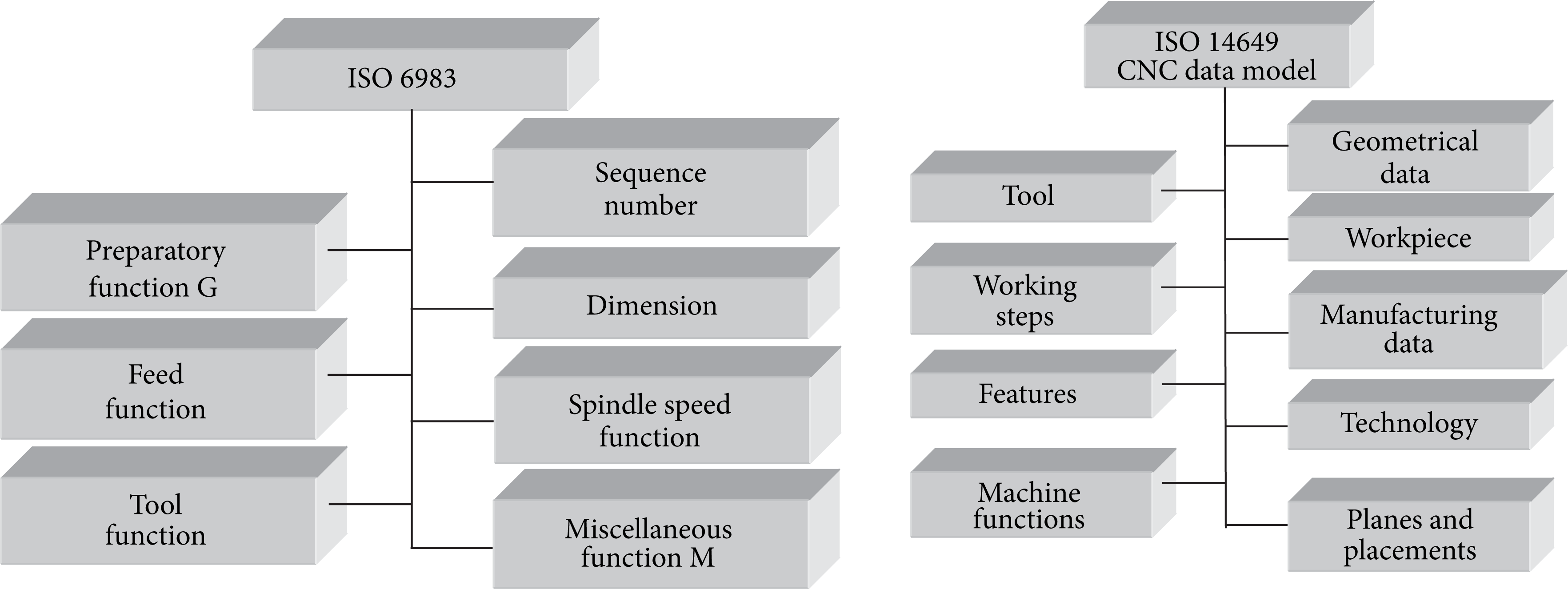
Comparison of ISO 6983 and ISO 14649 [6].
According to the facts listed above it is clear that in both approaches to NC program generation (on the base of standards ISO 6983 or ISO 14649) NC programmers and engineers work in one technological environment and they have at their disposal the full tree (history) of the model creation with all information. The problem occurs, when the 3D model doesn't exist yet, if the real object, as the original, is complex shaped and the geometric characteristics or dimensions are not clearly defined. In this situation it is necessary to find the way to obtain this information about the body.
The research relating to the obtaining of data for the shape and real (three dimensional) size of the subject is in quick progress today. Accurate, fast, and noncontact methods are substantial in many applications of industry and they include quality control, top surface control, or visual systems at assembly lines. The most accurate and the most suitable way to gain information about the topography of real product, in regard to the required accuracy and quality of the production in mechanical engineering, appears to be 3D digitization of investigated object with the utilization of modern technical equipment within the method known as reverse engineering.
Reverse engineering is the process of the existing component, composition, or product duplication without having the drawings, documentation or a computer model at your disposal. Reverse engineering includes all the activities which enable the determination of the function principle of the product, idea, or technology originally used at the product's development [7–10].
The digitization of real objects is possible due to scanning equipment which enables the conversion of the real three-dimensional objects into a digital form. The principle of the majority of this equipment is based on scanning the object's surface to its discrete points and it follows the digitized object that is presented on a computer as a large number of points in space, that is, the so-called point cloud [11, 12]. Scanners differ from one to another especially in the way the scanning of the object's surface points is implemented. The scanning equipment can be divided according to whether the scanning technology is contact or noncontact. The former concerns 3D scanners and stationary coordinate measurement systems CMM (Control Measuring Machine). This category offers the digitization equipment ranging from 3D desktop equipment to the systems used for measurement of large objects of several meters in size. The latter, noncontact systems of measurement, that is, scanners, generally operate on laser or optical principle.
For the most part, a choice of scanner type depends on the requirements posed on the accuracy of homogeneity between a real and a digitized model. Also, a significant factor is the size of the scanned component or possibly the mobility of the scanning equipment. The majority of scanners are limited by the scanning space in which it is possible to scan. 3D scanners are usually constructed to be able to scan objects as large as 50 cm. For more sizeable objects, larger equipment is produced. Another important factor when selecting a scanner is the scanning time. The fastest scanners are the laser ones.
Apart from hardware devices, a substantial role at digitization of 3D objects is played by software equipment. Individual scanning equipment uses its own software for processing the scanned data; however these need to be transformed several times and eventually transferred into a neutral format which CAD/CAM systems can operate with.
Experience shows that sometimes specifications given by laser scanner producers in their publications should not be trusted and that the accuracy of these instruments which are built in small series varies from instrument to instrument and depends on the individual calibration and the care that has been taken in handling the instrument. Every point cloud produced by a laser scanner contains a considerable number of points that show gross errors. The range error may vary from just a millimetre to values of several decimetres. At the request for higher precision of scanning (if scanned representation of the model differs from original by less than 1 mm), other supplementary techniques for surface contour rebuilding are needed, especially if the shape of object is irregular [13].
3. Problem Definition
The reverse engineering philosophy was applied at the production technology selection for a group of similar complexly shaped components, which geometrical and dimension characteristics were unknown. It is the concerned templates for the coiling of stator windings of electromotors for electric household appliances. Front and back views of the two prototypes of these templates for coil making are shown in Figure 2.
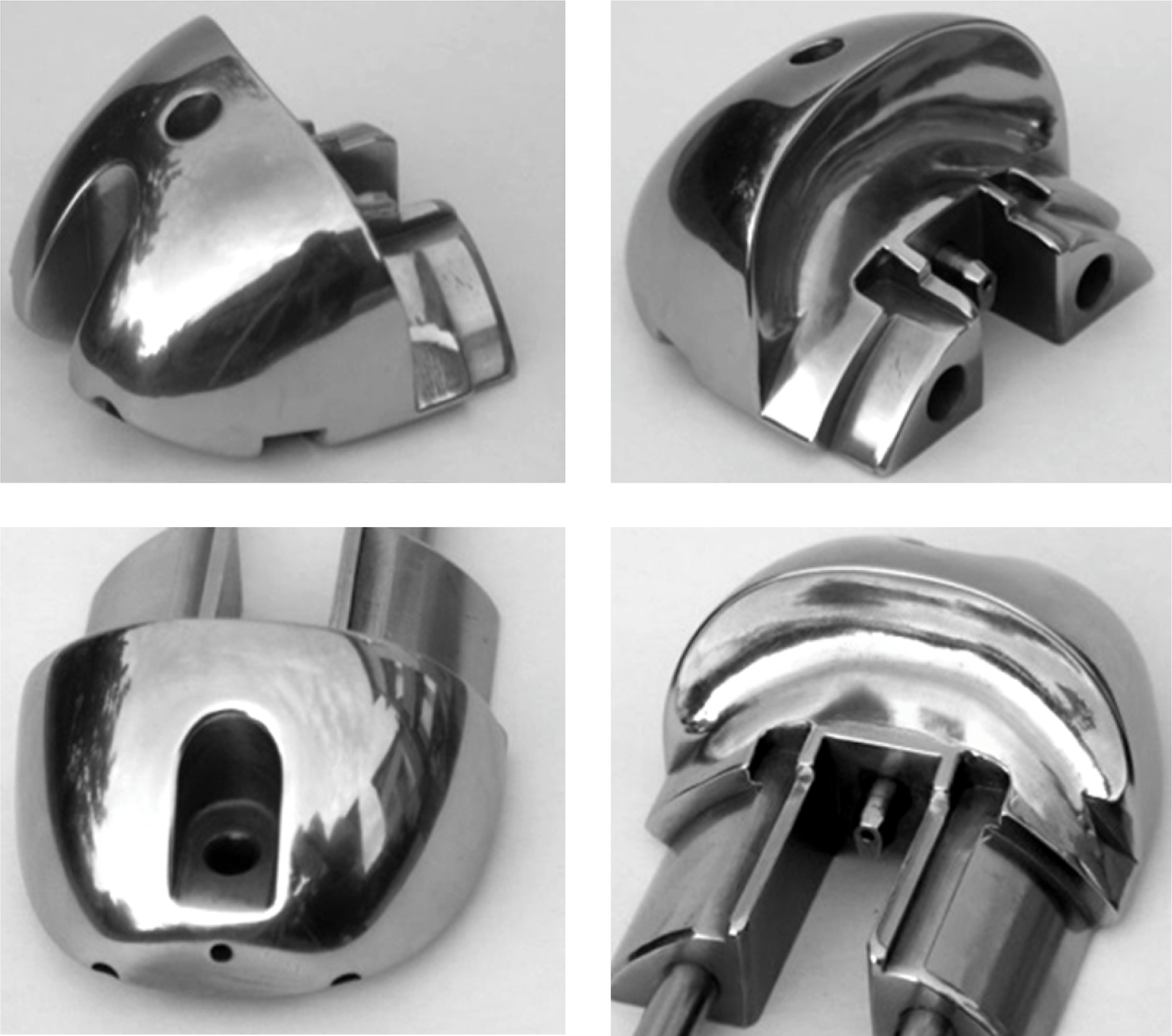
Front and back views of two templates for coil making stator of electromotor.
The template is a tool, which the magnetic wire of future coil slides on. The shape of the template controls not only the precise placing of magnet wire into its position, but also the number of coil loops, which consequently influences the power of electromotor. The winding needle, that leads the wire, works at high frequency (20–30 loops per second). The shape of the parts is asymmetric and it is not anywhere defined, neither in the drawing documentation.
The original parts used to be produced in a way that their finite shapes underwent a hand grinding into an anti-template. The delivery time was usually more than 3 months. This was the reason why the production organization that uses the templates had to have reserves of this technological component. In regard of the fact that for every type of coil it is necessary for another kind of winding (another number of loops, another minimal diameter of the coil, another material and various diameters of the wire and different out hang of the winding, etc.), in the manufacturing plant are templates used are organized into tens.
The templates are mirror-fixed into working position with the same templates (Figure 2). The magnet wire slides over the front surfaces of the templates; the back surfaces of the templates serve for wire positioning. The number of wire loops defines the power of electromotor. The virtual 3D model of assembly is shown in Figure 3(a) and the view of its real version in working position is in Figure 3(b). The final version of stator winding electromotor is presented in Figure 3(c).

Templates in working position and the final real version of stator winding of electromotor.
4. Materials and Methods
It was necessary to make these templates with high precision (± 0.2 mm in comparison with original) from high alloyed tool steel (STN 19 221, EN ISO C120U); therefore the casting or forming couldn't be chosen as production technology.
Based on available sponsor plant opportunities and its machinery, and also in view of the shape complexity of the parts, it has appeared to have selected 5-axes milling as the most suitable production technology. Unfortunately the NC program creation was not possible at the beginning because the dimensions of complex surfaces and their shapes were undefined, consequently undocumented. Only basic outside dimensions of raw parts and the position of auxiliary features (e.g., holes, chamfers, and rounds), which are necessary for their arrangement into the assembly, were known (Figure 4).

The part of the drawing of raw product with basic features.
Concerning the NC milling technology and the fact that the shape of the template was not defined, it was primarily necessary to obtain the data that characterized the geometry of the template surface. The most effective and most accurate method appeared to be the method of model digitizing by three-dimensional scanning [14]. A scanning device was chosen the scanner Roland PICZA LPX 250 (Figure 5), which was available at the authors’ workplace. All digitizing operations of this 3D scanner LPX 250 that uses an advanced noncontact laser sensor are controlled by the program Dr. PICZA3.

3D laser scanner LPX 250 [15].
3D scanner LPX-250 digitizes objects with both rotary and plane scanning [15]:
Rotarythis scanning mode (Figure 6(a)) is ideal for high-speed scanning of spherical and smooth-surfaced objects. Once the object is placed on the rotating table and after the scanning process's activation, the laser beam moves vertically, simultaneous with object rotation.
Planethis scanning mode (Figure 6(b)) is able to capture complicated (complex) angles and body side-cuts that could not be defined by rotary scanning. The LPX-250 laser beam scans a maximum of six surfaces at right angles.

The principle of rotary and plane scanning mode [15].
Considering the surface of the original component was too reflexive for the laser beam scanning (it was glossy so the laser beam reflects back from top surface), it was necessary to decrease its gloss values by spray-painting but not however in black, because this colour absorbs the laser beam. The original hand-made template was coloured by a grey undercoat colour. It was essential to evenly apply the sprayed layer as this factor could also affect the approximation stage of a created model toward its original and so a finite accuracy of the template was created on the basis of a virtual 3D model. The combination of concave and convex surfaces of the part caused that the laser beam was not able to recover the body as one whole entity.
The solution of this problem (Figure 7) consisted in the scan process repeating with various positions of the object and with various input data settings. Consequently the partial surfaces were merged in the software of the scanning environment and the unnecessary parts were deleted. The wire and volume presentations of scanned templates are shown in the Figure 8.

Deficiency of scanning.

The wire and volume presentation of scanned template.
For next process it was necessary to export the acquired data from the software Dr. PICZA3 and subsequently import them into Pixform software. Figure 9 shows the imported part that is represented by so called “cloud of points.”

Imported part as a points cloud in software Pixform.
The software application listed above enables it to cover the cloud of points by one complex surface (polygonal mesh) that was created by plenty of little polygonal surfaces. The precision of covering depended on the number of selected checkpoints. This software also allowed it
to modify the polygonal meshes by means of editing control points, polygon edges, and surfaces (removing, moving, or adding new surfaces),
to reduce polygonal meshes, that is, a reduction in the number of polygons in the meshes, at the expense of the quality and display fidelity, however,
to partially polish the obtained model, however, not with a sufficient accuracy.
Obtained polygonal surfaces covered over the scanned object in PIXFORM environment for 100 and 300 checkpoints are shown in the Figure 10.

Polygonal meshes in PIXFORM software.
Obtained data represents the geometry of the model with the unsmoothed top and curves, which are not continuous. Also some technological features (e.g., the holes) were not scanned completely, but only as the surfaces that indicate the position of these features. Virtual model was in this faulty version exported in STEP or IGES format and imported into CAD/CAM system Pro/Engineer (Figure 11).

The imported model of part to CAD/CAM system.
Software Pro/Engineer was selected based on the authors experience and on the base of its availability. In the process of 3D model creating and finalising, the various tools and techniques were used, which this CAD/CAM system offers to a user. To work with complex shaped templates easily it was advantageous to utilize the operations with surfaces. For this purpose, sections were first created by the imported model in three perpendicular directions. The points generated in the curves intersection and they define the shape of template's top in individual cross section planes. Bezier and Spline types are mostly used for approximating the curves. Secondly the curves were described via mathematical apparatus in software Matlab and they were expressed by polynomial equations, whereby their smoothing was achieved (Figure 12).
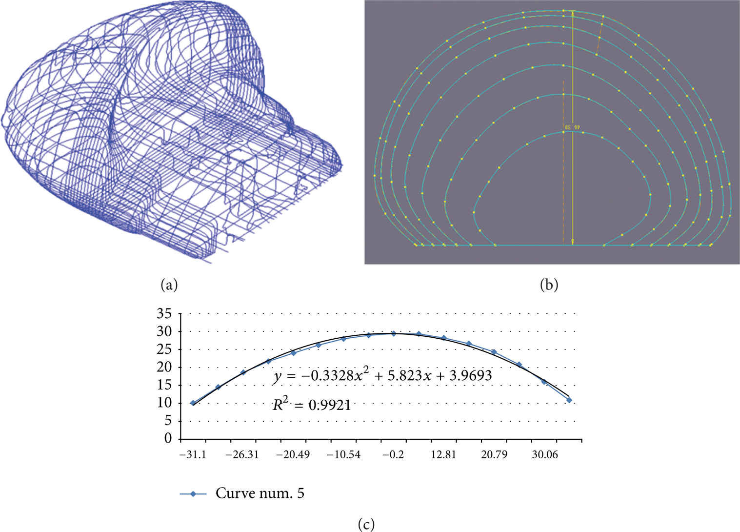
(a) all curves in three directions, (b) curves in one section plane, and (c) curve definition by polynomial function.
By means of equations, the curves were modelled in Pro/Engineer again and in the next step the curves were covered with a needed surface coat. As with the curves, in Pro/E environment it was also possible to control, analyse, and modify the curvature and “smoothness” of the selected surface (Figure 13).

Created surface and its analysing.
All top surfaces were joined into one continual top surface that responded to the template shape. This surface was filled by the “material” so the volume 3D model originated. The virtual model prepared in this manner was created as Pro/Engineer system's own element so the geometric data describing this surface were readable also for CAM module of software and they were usable for NC program generation.
5. Results and Discussion
The designed volume of 3D model, shown in the Figure 11, was in Pro/Engineer compared to the geometry of the scanned shape. The gaps between points, in which the measuring was done, were 1 mm and the tolerance was ± 0.1 mm. It could be said that 97% of the created top surface was inside the tolerance (the required precision was ± 0.2 mm). However it is necessary also to say that the comparison was done in the phase, when only the basic body of the part was modelled (before the features such as are holes and chamfers were created), so in these locationswere areas (blue and red coloured) which differed from the scanned model more than 0.2 mm (Figure 14(b)).

The comparison of created basic volume of model and scanned data.
Seeing that the basic volume of the model corresponded to the original in required accuracy, the features specified by the drawing (holes, chamfers, rounds) could be modelled to achieve the final shape of the part. The definitive versions of 3D models are shown in the Figure 15.
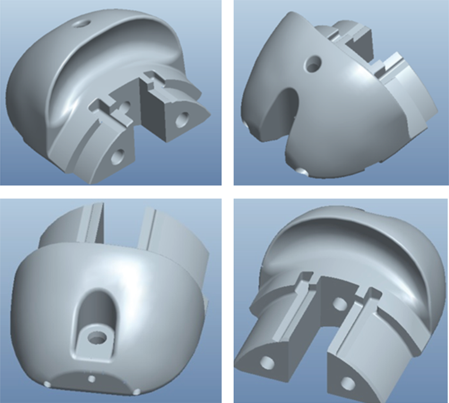
The final shape of the model.
For the created 3D model to be verified the geometry data was exported from CAD/CAM system to STL format and a new template from hardened plastic material was made by rapid prototyping method (Figure 16).

Template made by rapid prototyping.
This real plastic part was firstly compared with the original hand-made steel part by means of 3D measuring equipment (Figure 17) and then it was tested in a real situation as the component of a technological machine. The plastic part fully confirmed the functionality of the model in real conditions during the process of stator coil winding.

The comparison of new manufactured part and original.
Based on the geometrical data of virtual 3D models, the NC programs for every type of template was prepared very easily by means of STEP-NC standard. These programs were enabled in case of a need to make very quick adequate numbers of a specific type of the template.
The automation of the manufacturing process is one of the main goals in present days. It has been realised thanks to the quick development of information technology and by the sequential application of computer aid into all areas of production. Many of the hand-made prototypes are created without drawing documentation and so the manufacturing of such real parts is very complicated. The utilization of computer techniques can become the basis for new technology of their manufacturing suggestion, especially if mass production is necessary. The suitable use of modern methods, technologies, and equipment (computers, NC machines, and scanners) and its correlative combination can greatly decrease delivery time of parts, investment quantity blocked in stores, and financial demands of their acquisition.
The evaluation of the influence of the model that was created within Reverse engineering method, the costs, and savings is in the Figure 18 [16, 17].

6. Conclusion
The paper deals with the process of 3D digitization as a tool for increasing production efficiency of complex shaped parts. The concept of reverse engineering and new model of NC program STEP-NC is used for production of winding stators templates used in electric household devices.
The template is a tool, which the magnetic wire of future coil slides on. The shape of the template controls not only the precise placing of magnetic wire into its position, but also the number of coil loops, which consequently influences the power of electromotor, winding the needle that leads the wire to work at high frequency (20–30 loops per second). The shape of the parts is asymmetric and it is not anywhere defined, neither in the drawing documentation.
The original parts used to be produced in a way that their finite shapes underwent a hand grinding into an antitemplate. The delivery time was usually more than 3 months. This was the reason the production organization that uses the templates had to have a reserve of this component. In regards to the fact that for every type of coil it is necessary for another kind of winding (different number of turns, different minimum winding diameter, different material and different thickness of wire, and different winding overhang), the types of templates used in the manufacturing are organised into tens.
By that technique is possible to shorten the delivery time and to decrease the cost with the utilization of innovative technologies within the available means and capabilities of the company. The specific choice of a new process plan was influenced not only by unknown geometry and the shape complexity of its parts, but also the need to maintain their high dimensional accuracy. The next important factor influencing the choice of the new strategy was the material of products. It was necessary to make these templates from structurally high alloyed tool steel (STN 19 221, EN ISO C120U), therefore the casting or forming could not be chosen as production technology. The most suitable way to increase production efficiency of the templates seems to approach with the utilization of reverse engineering, a concept that helps to define the shape geometry of the parts. As a means of digitization and specification of complex shaped surfaces, a 3D laser scanner was used. Its output data were processed and transformed in CAD/CAM system by means of several software applications, in which a new 3D model of the template was created. The virtual model subsequently served as the basis for creating the NC program using the new object-oriented methods of STEP-NC.
After the 3D model creation and its verification and after the generation of the NC program, the delivery time for Slovak producer had shortened compared to the foreign producer by about 90–98% (about 80–88 days from the initial minimal 90 days), the number of templates in store could be reduced by a minimum of 50%, and the price of the templates produced in Slovakia was lower than 60% in comparison with foreign suppliers.
Conflict of Interests
The authors declare that there is no conflict of interests regarding the publication of this paper.
Footnotes
Acknowledgment
This paper originates with the direct support of Ministry of Education of Slovakia by Grants VEGA 1/0934/14 and KEGA 013TUKE-4/2014.