
Abstract
During turbocharger rotor speed-up tests, the sensor installed in the compressor greatly affects the rotor dynamics. The effect of the floating bearing stiffness coefficient on the critical rotational speeds and the shaft dynamic response due to the unbalanced mass were both analyzed using rotor dynamics theory and a finite element analysis. The results illustrate that the initial sensor design reduced the 3rd order critical speed to lower than the maximum normal operating speed which leads to the rubbing and failure of the rotor during the speed-up test. The sensor structure was then optimized to reduce the negative influence of the sensor on the rotor dynamic characteristics to ensure stability during rotor speed-up tests.
1. Introduction
A turbocharger works by using energy in the exhaust gas of a diesel engine to provide pressurized air to the engine. A turbocharger can significantly improve the engine power output without any emissions increase. Moreover, turbocharged engines have less oil consumption and less gas emissions than high-emission naturally aspirated engines with the same power capacity, which explains why turbochargers have been extensively used in recent years.
Turbochargers vibrate due to unbalanced masses and aerodynamic forces during operation. Excessive vibrations can then loosen connecting components, such as the bolts, which will lead to turbine casing cracks and lighter failure will degrade engine performance because of gas leaks in the turbocharger and will increase the noise because of the loose connections. The turbocharger will eventually fail due to bearing wear and impeller casing rubbing resulting from the loose connections or crack propagation. End users need highly reliable turbochargers, so reducing vibration failures is one of the key factors for evaluating turbocharger design optimizations.
Rotor speed-up tests are frequently used by turbocharger manufacturers to test the rotor vibration characteristics. A sensor is usually installed in the impeller to collect speed and displacement signals during operation. However, the sensor installation changes the rotor structure and an unreasonable sensor design can cause excessive rotor vibration. Therefore, the impact of the sensor on the shaft stability should be evaluated to minimize vibrations caused by the sensor. This study focuses on a diesel engine turbocharger with an initial sensor structure design and an equivalent sensor for the analysis model with the same mass and rotational inertia installed at the end of the compressor impeller in a rotor speed-up test. During the test, the turbocharger speed will gradually increase to the maximum of 130000 rpm (the normal operating speed range is 60000∼130000 rpm) after ten minutes. The vibrations continued to increase at this speed, with much noise and eventually impeller fragmentation at 37's after severe rubbing with the casing as shown in Figures 1 and 2. Hence, the rotor dynamics including the critical speed and the unbalanced response must be analyzed to eliminate the unreasonable sensor design and to optimize the sensor design to meet the rotor stability requirements.
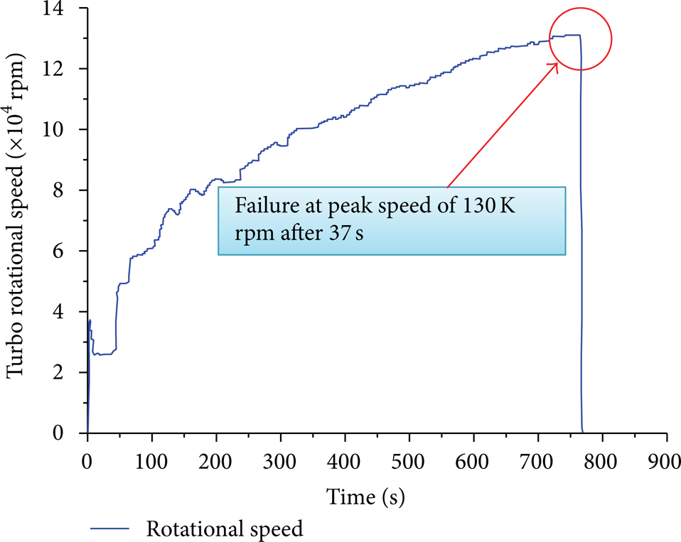
Rotor speed-up test with the initial sensor design.

Broken compressor and turbine.
The speeds of diesel engine turbochargers are normally tens of thousands or even hundreds of thousands of rotations per minute, with the operating speeds of most rotors higher than the low-order critical speed, so the operator must carefully consider the rotor dynamics. Thus, the critical speed must be accurately calculated to guarantee that the rotor operating speeds are beyond the critical speed for the supercharger rotor design. The finite element method has been widely used for turbocharger rotor critical speed calculations. Liao et al. [1, 2] used a one-dimensional finite element model to predict the rotor system critical speeds and vibration modes using a simplistic subspace iteration method to analyze the effect of the support stiffness on critical speed. Wan et al. [3] used a three-dimensional finite element model to study the impact of prestressing on the critical speed. In addition to the critical speed, unbalanced masses in the pressure impeller and turbine also strongly influence the rotor stability. Kirk et al. [4, 5] analyzed oil film instabilities in turbocharger rotors by a linear model and pointed out that the bearing parameters were the main reason for the oil film instability which can be suppressed by a slightly unbalanced rotor. Holt et al. [6] verified that a rotor unbalance can stabilize the originally unstable speed range through nonlinear transient response analysis and testing. However, there are few studies on the impact of sensors on the turbocharger dynamics.
Rotor dynamic theory is used here with a 3D finite element model to calculate the critical speed of a turbocharger and the vibration modes. The shafting response amplitude caused by the imbalance and the impact of the sensor installation on the rotor dynamics are analyzed to show that rubbing leads to failure of the turbocharger rotor with the initial sensor design during speed-up tests and that an optimum sensor design eliminates the rubbing and failure.
2. Rotor Dynamics Finite Element Analysis Theory
2.1. Shaft Modal Analysis
The critical speed is the rotational speed that corresponds to the structure's resonance frequency (or frequencies). The critical speed occurs when the natural frequency is equal to the excitation frequency. The excitation may come from an unbalance that is synchronous with the rotational velocity or from any asynchronous excitation.
The rotor dynamics equation including the gyroscopic effect, G, in a stationary reference frame is [3]

where
M is the mass matrix;
K is the generalized stiffness matrix;
[C] is the damping matrix;
[G1] is the gyroscopic matrix corresponding to a unit rotational velocity Ω. The gyroscopic effect increases the positive procession critical frequency and decreases the negative procession critical frequency;
q is the displacement vector;
Ω is the rotational speed of the reference rotor. If the rotor contains several rotors, the gyroscopic matrices and the circulatory forces are multiplied by a proportionality factor.
A solution is sought in the following form:
Substituting (2) into (1) leads to

The solution to (3) is

The rotor system will become unstable if α>0.
β is the natural frequency.
The critical speed is the angular velocity that has a natural frequency

Critical speeds can be determined using a Campbell diagram analysis to calculate the complex eigenvalues and the intersection points between the natural frequency curves and the excitation line. This sweeping method couples the pseudomodal algorithm with the Lanczos algorithm. This is an approximate but economical method with the subspace bi-iteration algorithm leading to the exact solution. These algorithms can be used to solve large problems with several million degrees of freedom. The multifrontal algorithm is adopted to solve the linear system of equations.
The critical speeds can also be determined by directly solving a new eigenproblem which is called direct method. For an undamped rotor, the dynamics equation, (1), can be rewritten as

The solution is sought in the following form:

where {ϕ} is the mode shape and β is the natural frequency.
The critical speeds are natural frequencies that are proportional to the rotational velocity. The proportionality ratio υ is defined as
Substituting (7) and (8) into (6) leads to the new eigenproblem
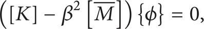
where

This problem can be solved using an unsymmetric eigensolver. The eigensolutions of this algorithm are the critical speeds. This method can only be used with undamped systems and with constant stiffness.
2.2. Shaft Response Analysis
A shaft response gives the harmonic response of a structure with rotating isotropic parts. The harmonic analysis solves the following equation in a nonrotating coordinate system:

where
B(Ω) is the generalized damping matrix including the gyroscopic matrix;
q(ω) is the displacement vector;
g(ω) is the loading.
Two algorithms are used to compute the harmonic response. Modal algorithms project the forces and matrices to a modal basis obtained from a pseudomodal method coupled with the Lanczos algorithm for a specified number of eigenvalues. Direct algorithms use a direct solver at each frequency in a defined range which allows local nonlinearities (clearances, nonlinear stiffnesses, etc.). The solution is normally coupled with an equivalent linearization technique. The bearing damping must be taken into account to get accurate rotor vibrations for the response calculation.
3. Initial Design Analysis
3.1. Critical Rotational Speed and Unbalanced Harmonic Response Analysis
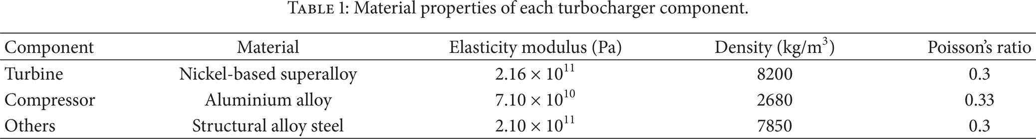
The diesel engine turbocharger rotor bearing system analyzed here includes the shaft, compressor, and turbine, with an axial length of 170 mm, as shown in Figure 3. The rotor is supported by two radial floating bearings with one on each side. The compressor impeller material is an aluminium alloy and the turbine is made from a nickel-based superalloy, while the other parts are alloy steel, with the properties given in Table 1. This type of turbocharger operates at speeds of 0∼130000 rpm, with 60000∼130000 rpm used for normal stable operation. A three-dimensional model was used to ensure the accuracy. Some chamfers, key grooves and other details were initially ignored to simplify the geometric model. The model used tetrahedral elements with a total of 64,463 elements and 15,676 nodes. The bearing was connected to the rotor model using bearing elements as shown in Figure 4.
Material properties of each turbocharger component.

Diesel engine turbocharger rotor structure.

(a) Turbocharger rotor with initial sensor design and (b) bearing system and finite element model.
The bearing finite element analysis was arranged with two radial floating bearings. The stiffness coefficients of the floating bearings depend on their structure and the dynamic properties of the lubricants with typical stiffness coefficients of 7 × 10⁶ N/m to 7 × 10⁷ N/m. The damping in the bearing was not taken into consideration in the critical speed analysis. A ground bearing was used to simulate the floating bearing in the finite model with the casing assumed to be rigid. The dynamic characteristics of the turbocharger rotor were studied before and after the sensor installation. Different critical speeds were calculated for different bearing stiffness coefficients with the unbalanced mass of 2.5 gm exerted to compressor and turbine impellers separately. The damping of the floating bearing was considered for the unbalanced harmonic response analysis shown in Figure 5.

Unbalanced masses at the two ends of the turbocharger shaft.
3.2. Results and Discussions
The oil forces in the bearing were modelled by a spring element with a stiffness coefficient. Past experience and the comments by Liao et al. [1] lead to the floating bearing stiffness being varied from 7 × 10³ N/mm to 7 × 10⁴ N/mm. The influence of the floating bearing stiffness coefficient on the critical speed of the turbocharger rotor system without a sensor is shown in Figure 6(a). Increasing the stiffness coefficient from 7 × 10³ N/mm to 7 × 10⁴ N/mm increased the first- and second-order critical speeds only by a small amount, while the third-order critical speed increased significantly. The normal operating speed range of the turbocharger is 60000 rpm∼130000 rpm, within the speed range of 38500 rpm∼228600 rpm shown in Table 2 from the maximum second-order critical speed to the minimum third-order critical speed with a relatively large safety margin. Figure 7(a) shows the harmonic response analysis result for the compressor impeller displacement of the turbocharger without the sensor for a smaller bearing stiffness. The peak displacements occur at 15000 rpm and 30000 rpm. However, the turbocharger is always quickly accelerated in normal operations to get past the low velocity zone (<60000 rpm), so the displacement at the peak speed will not be that large because of the acceleration over the critical point. In the normal stable operating range, the amplitude should be stabilized at around 0.006 mm to maintain its safety and reliability.
Predicted critical rotational speeds.

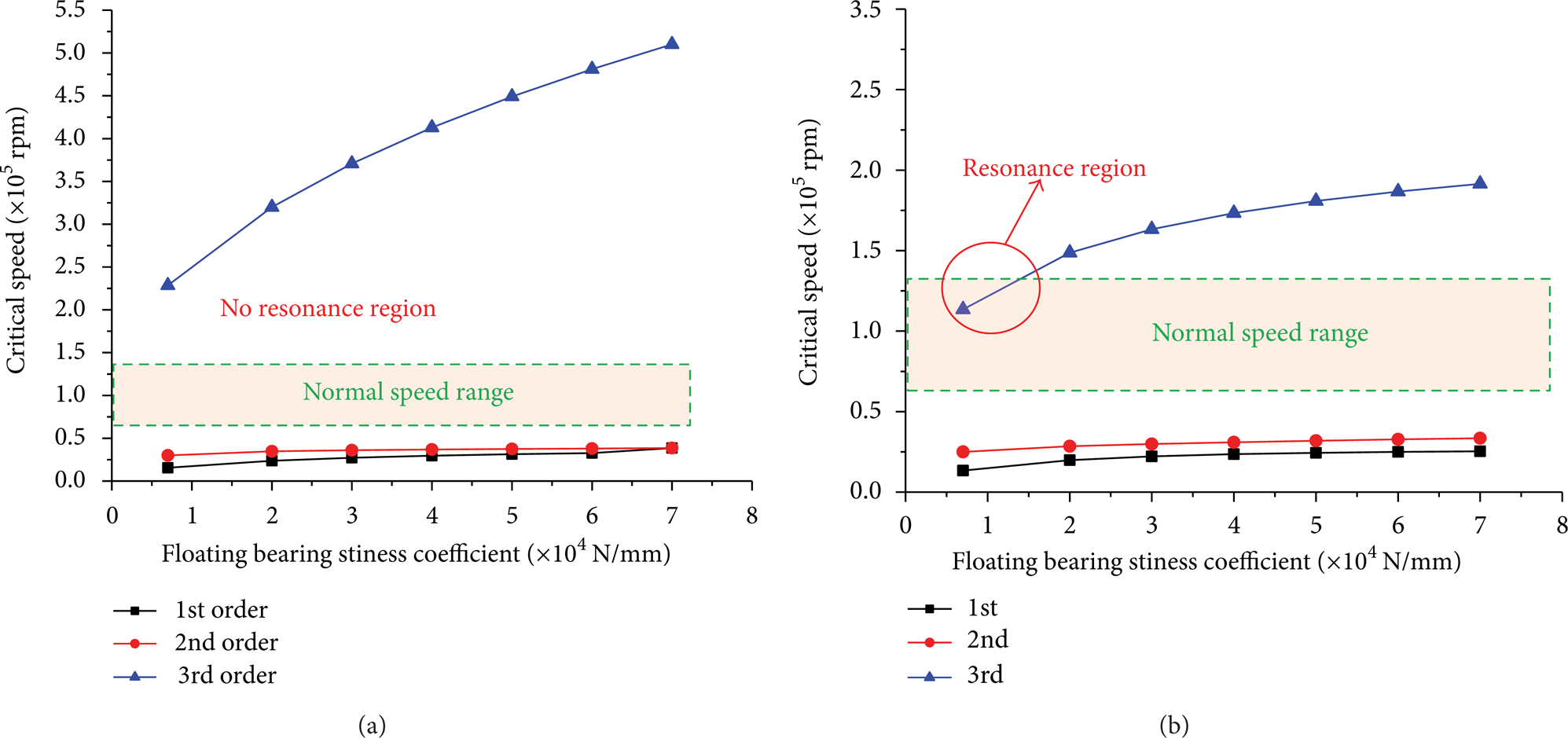
Turbocharger rotor system critical speed analysis (a) without sensor and (b) with initial sensor design.
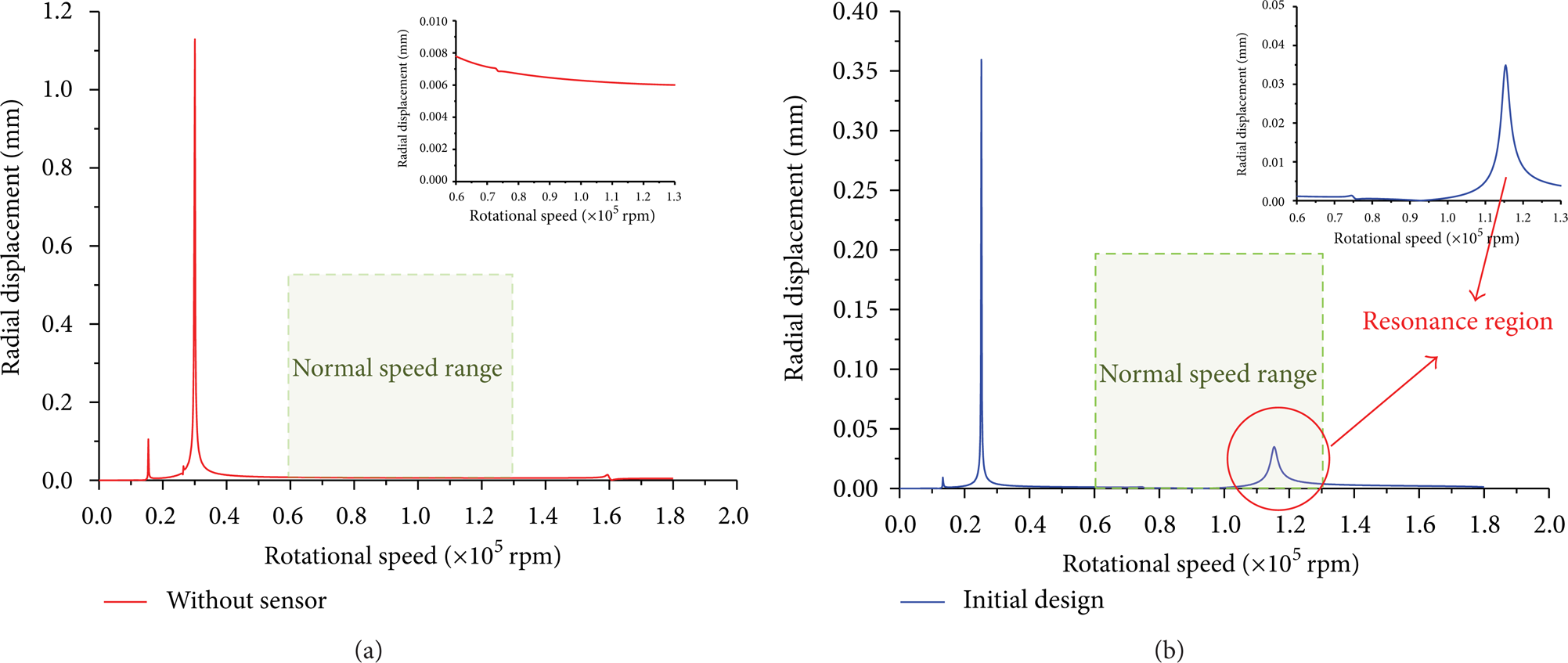
Turbocharger rotor system harmonic response for a bearing stiffness coefficient of 7 × 10³ N/mm (a) without sensor, (b) with initial sensor design.
Figure 6(b) illustrates the turbocharger rotor critical speed characteristics with the initial sensor design. The third-order critical speed is much lower than in Figure 6(a), with a safety running speed range of 33500∼113500 rpm as shown in Table 2. For a smaller bearing stiffness of around 1.2 × 10⁴ N/mm, the third-order critical speed falls within the normal operating range which will result in resonance with a resonance region of 115000 rpm∼130000 rpm as shown in Table 2, which coincides with the rubbing and turbocharger failure at 130000 rpm observed in introduction real system. The harmonic response analysis of a turbocharger rotor system with a lower (7 × 10³ N/mm) stiffness shown in Figure 7(b) shows that the peak displacement, that is, the largest vibration, will occur at 115000 rpm in the stable operating area. The mode shapes in Figures 8(a)–8(c) show that the first-order rotor vibration mode is rigid swing, the second order is compressor impeller vibrations, and the third order is both compressor vibrations and turbine vibrations, where the compressor vibrations are more intense. The mode shapes in Figures 8(d)–8(f) show that the sensor has little influence on the 1st∼3rd order rotor vibration modes. Thus, the unreasonable sensor design only caused the third-order turbocharger critical speed to decrease significantly and eventually lead to the rubbing fault in the rotor speed-up trials. Thus, the sensor structural design should be improved to minimize the impact on the bearing dynamics.
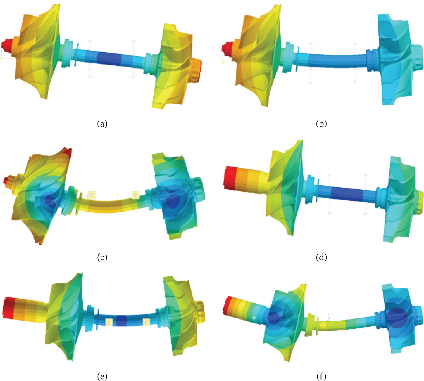
Vibration modes of the turbocharger rotor system. ((a) to (c)) 1st∼3rd order modes without the sensor. ((d) to (e)) 1st∼3rd order modes with the sensor.
4. Best Design
The analysis shows that the initial sensor design significantly reduced the 3rd-order critical speed of the turbocharger and increased its vibration amplitude to cause resonance damage at 130000 rpm. Thus, the sensor design should be improved to minimize its impact on the turbocharger dynamics. The aim of this optimization is to increase the 3rd-order critical speed to avoid the normal operating speed range.
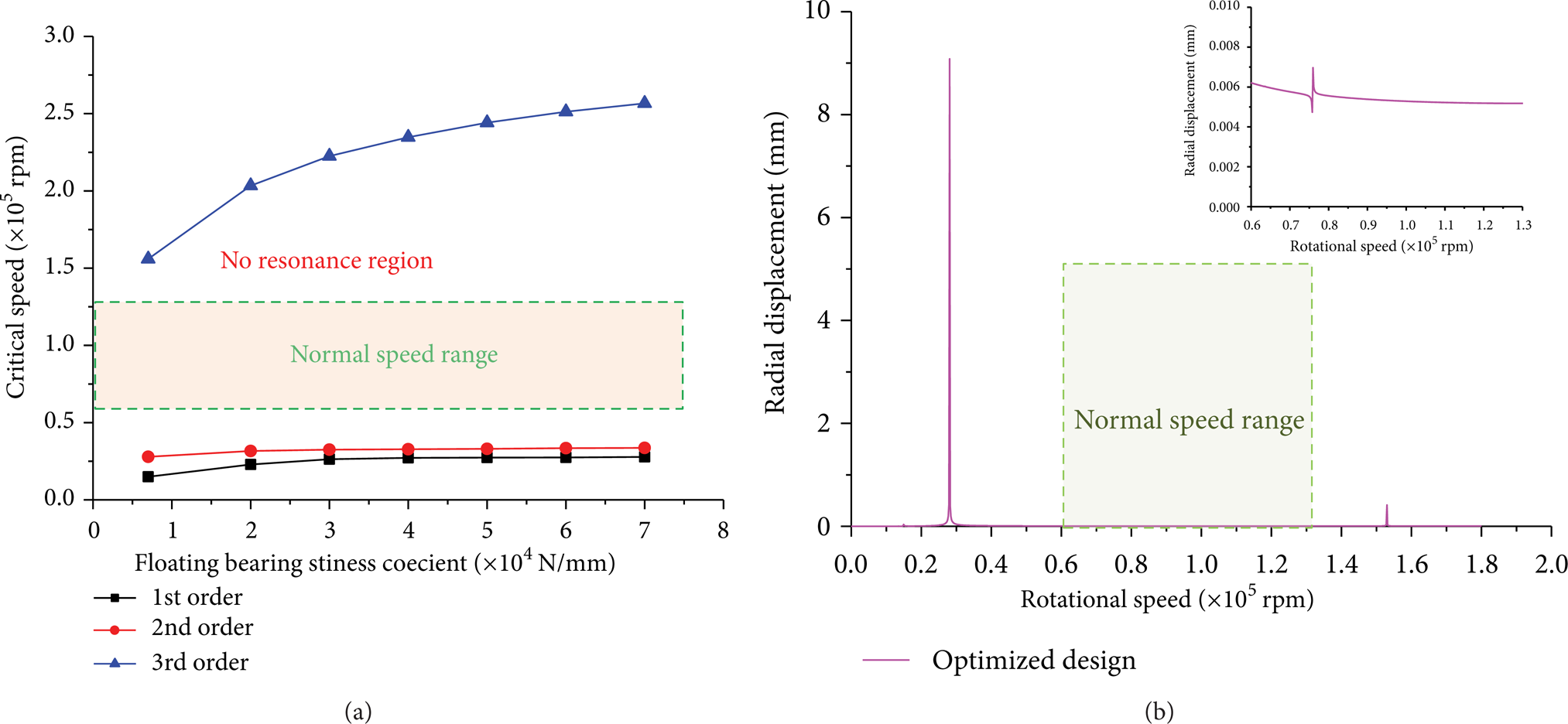
The metal casing of the sensor was then modified without changing the shape of the internal electronics in the sensor. First, the metal casing was thinned and designed with a stepped wall thickness as shown in Figure 9. The metal casing thickness was reduced from 5 mm with more than 10 cases analyzed with H1 set to 4.5 mm, 4 mm, 3.5 mm, 3 mm, and so forth, and H2 set to 5 mm, 4.5 mm, 4 mm, 3.5 mm, and so forth. The analysis proved that the best design had H1 = 0.8 mm and H2 = 1.75 mm. The critical speed and harmonic response of the turbocharger were analyzed with the optimized design having H1 = 0.8 mm and H2 = 1.75 mm. As shown in Figure 10(a), the 3rd-order critical speed of the rotor now differs substantially from the normal operating region which avoids resonance. The pressure impeller response amplitude within the normal operating region is now 0.0055 mm∼0.0062 mm, similar to the response amplitude without the sensor installation in the same region of 0.006 mm∼0.007 mm. Thus, the sensor in this design has less impact on the harmonic response of the turbocharger rotor.
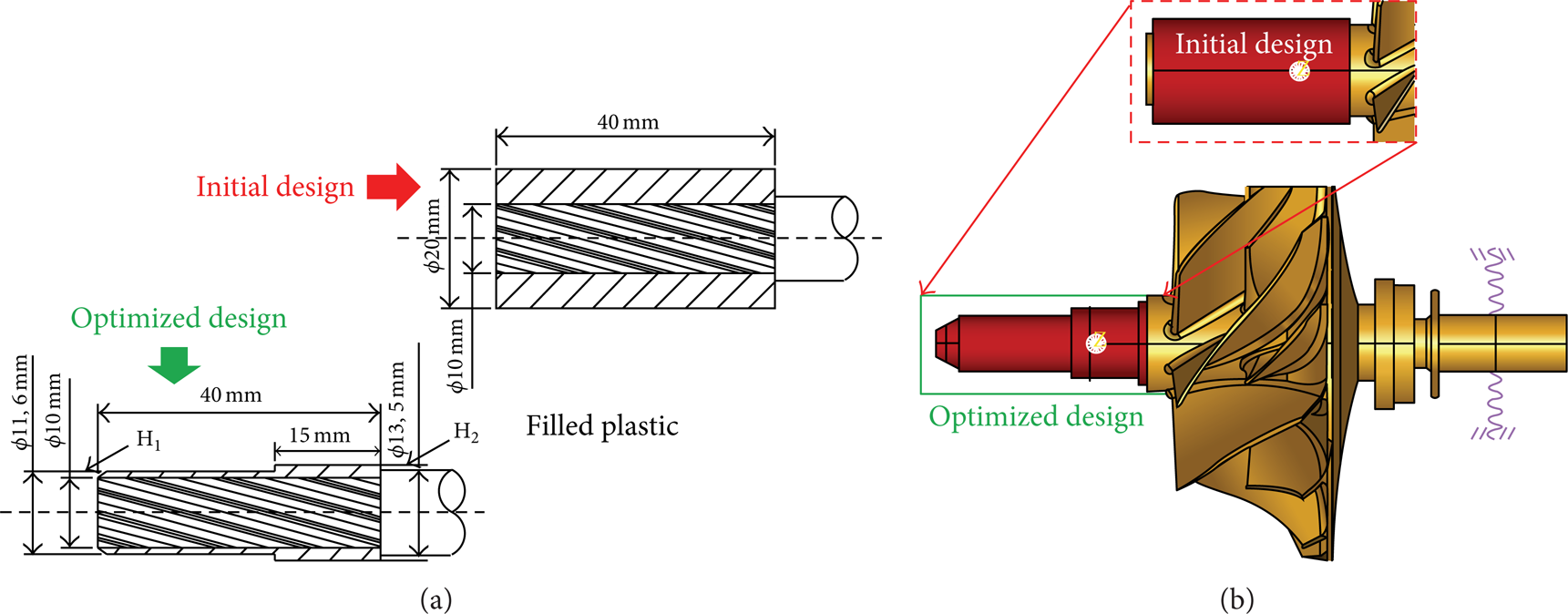
Optimized sensor structure, (a) structure diagram and (b) 3D model.
Rotor dynamics analysis of turbocharger with the optimized sensor installation. (a) Critical Speed. (b) Harmonic Response.
5. Experimental Results
The optimized sensor with H1 = 0.8 mm and H2 = 1.75 mm was then installed at the end of the diesel engine turbocharger compressor for a rotor speed-up test with the turbocharger installed in a test engine. High speed exhaust gas then rotated the turbine and the turbocharger. As the gas flow rate increased, the rotational speed of the turbocharger slowly increased. After about 700's, the rotor reached the highest speed of 13 K rpm and maintained stable operation without rubbing for more than 3 minutes as shown in Figure 11. Thus the test results verify the numerical results and the optimized sensor design can provide stable operation.

Turbocharger rotor speed-up test with optimized sensor.
6. Conclusions
Rotor speed-up tests are often used to test the stability of diesel engine turbochargers. Key parameters are measured by installing a sensor at the end of the impeller during the test. However, the sensor installation will change the rotor system structure and its dynamics such as the critical rotational speed. Even worse, rubbing can occur between the rotor and the casing with an inappropriate sensor design. Therefore, the sensor must be carefully designed for stable operation.
Rotor speed-up tests verified that the dynamic response can be analyzed through using rotor dynamics theory and 3D finite element model. The metal casing design was optimized here using numerical model with predictions of the turbocharger rotor rubbing possibility. The analysis improves the design efficiency, reduces costs, and reduces the risk of sensor failure due to rubbing. The simulation and experimental results show that the metal casing of the sensor should be thinned to a ladder structure which ensures that the structural strength has a smaller reduction of the third-order critical speed of the rotor system so that the critical speed is higher than the stable operating speed to avoid rubbing.
Conflict of Interests
The authors declare that there is no conflict of interests regarding the publication of this paper.
Footnotes
Acknowledgment
This work was funded by the Specialized Research Fund for the Doctoral Program of Higher Education of China (Grant no. 20120002110011).