
Abstract
Fully developed periodic laminar flow and heat transfer in an isothermal wall tube with 45° upstream rectangular winglet vortex generators (RWVG) with closed end are investigated numerically. The fluid flow and heat transfer characteristics are proposed for Reynolds numbers based on the diameter of the tube, Re = 100 to 2000. The RWVGs with an attack angle of 45° are mounted with in-line arrangement on both sides of a plate and the closed tip pointing upstream is inserted in the middle of the tested tube to produce longitudinal vortex flows through the tested section. Effects of different blockage ratios (b/D, BR) and pitch spacing ratios (P/D, PR) on heat transfer, pressure loss, and the thermal enhancement factor (TEF) in the round tube are studied. The results show that the longitudinal vortex flows can induce impinging flows on a tube wall leading to an extreme increase in heat transfer rate over the round tube for all cases. Additionally, the rise in the BR and the reduction of PR result in the increase of both the Nusselt number and friction factor values. The optimum TEF in the range studied is around 2.9 at BR = 0.15, PR = 1, and Re = 2000.
1. Introduction
The augmentation on heat transfer is the main aim, which is of considerable interest to investigators as it leads to saving energy and more cost. Both reducing energy lost from ineffective use and improvement of performance have become an increasingly significant mission for design and operation engineers for many systems because of the increase in energy demand all over the world. For decades, numerous researches have been carried on heat transfer enhancement. These researches focused on studying a technique that not only increases heat transfer but also reaches higher thermal performance. The higher heat transfer rates with various enhancement techniques can result in substantial energy savings, more compact and less expensive equipment with higher thermal performance.
Heat transfer augmentation techniques have been widely used in heat exchanger equipment, such as chemical process, air condition, heat recovery, and so forth. One of the widely used heat transfer enhancement techniques is inserting turbulators or vortex generators in channel flow. The longitudinal vortex generators applied in various heat exchangers have received considerable attention for the advantage of heat transfer enhancement.
The uses of winglet vortex generators were reported by many researchers. For example, Fiebig et al. [1] experimentally investigated three tube rows heat exchanger elements with delta winglets. They concluded a 55–65% of heat transfer augmentation with corresponding 20–45% increase in the apparent friction factor for in-line arrangement case. Biswas et al. [2] numerical studied the flow structure and heat transfer characteristics in a channel with vortex generators on flow structure and heat transfer characteristics in a channel. Biswas et al. [3] claimed that the main vortex, a corner vortex, and induced vortices appeared behind a winglet vortex generator position. Chen et al. [4] numerically investigated punched winglets vortex generators in an oval tube on heat transfer and flow structure for both in-line and staggered arrangements. The investigation on the effect of annular and delta winglet vortex generators in fin-and-tube heat exchanger with dye-injection visualization was reported by Wang et al. [5]. Numerical simulation to investigate the heat transfer performance of a rectangular channel with a pair of rectangular winglets VGs punched out from the wall of the channel was presented by Wu and Tao [6]. They analyzed the results from the view of field synergy principle [7–9]. Joardar and Jacobi [10] experimentally estimated the potential of multi-row inline-tube heat exchangers with winglet vortex generator arrays. They also found an increase in the heat transfer coefficient around 16.5% to 44% for the single row winglet arrangement with an increase in pressure loss of less than 12%; for the three-row vortex generator array case the heat transfer coefficient increases from 29.9% to 68.8% with a pressure loss penalty from 26% to 87.5%. The comparison of the thermohydraulic performance of the finned oval tube heat exchanger element with one to three rows of winglets was studied by Chen et al. [11]. He et al. [12] numerical studied heat transfer enhancement by punched winglet vortex generator arrays in fin-and-tube heat exchangers. They also summarized that in the punched VG cases, the corner vortex flow shows significant effect on the heat transfer performance higher than the main vortex flow. The combination between delta winglet vortex generators (DWVG) and riblets for wall/fluid heat exchange enhancement was reported by Colleoni et al. [13]. Gong et al. [14] numerically studied the effect of combined rectangular winglet pairs (CRWPs) on flow structure and heat transfer characteristics in the wavy fin-and-tube heat exchanger. The numerical results showed that the wavy fin-and-tube heat exchanger has better heat transfer performance when the winglets were punched on the suction side of the wavy fin. Min et al. [15] numerically examined six main parameters of the combined rectangular winglet pair (CRWP) on both heat transfer characteristics and flow behavior in a turbulent region. The experimental study on the performance of a novel fin-tube air heat exchanger with delta winglet pairs was presented by Wu et al. [16].
Most of earlier investigations on flow behavior and heat transfer characteristics have considered delta and rectangular winglet vortex generators in fin-and-tube heat exchangers only. Thus, the numerical investigation of rectangular winglet pairs with closed end inserted in a round tube has rarely been reported. In this present paper, the numerical computations for the fully developed periodic laminar forced convection in a round tube with pairs of upstream closed end rectangular winglet vortex generators (RWVG) inserted in the middle of the tested tube are investigated. The use of RWVG is to changes in the flow structure and thermal performance improvement by creating longitudinal vortex flow over the tested tube.
2. Numerical Modeling
2.1. RWVG Geometry and Computational Model
Figure 1 displays a circular tube with 45° upstream closed end rectangular winglet vortex generators (RWVG) inserted in the middle of the tested tube in tandem for in-line arrangement on both sides of a plate. Periodic conditions in which the velocity field and temperature profile repeat themselves from one cell to another module are used for inlet and outlet of the computational domain. The theory of periodically fully developed flow and its solution procedure has been described in [17]. The inlet air temperature, Tin, flows over a 45° RWVG where b is the height of RWVG, D is set to 0.05 m, is the tube diameter, and b/D is identified as the blockage ratio, BR. The distance between RWVG module is set to L = D in which L/D is defined as the pitch spacing ratio, PR. To examine the effect of the interaction among winglet, BR and PR are varied in a range of 0.05–0.20 and 1–2, respectively, for α = 45° in the present investigation.
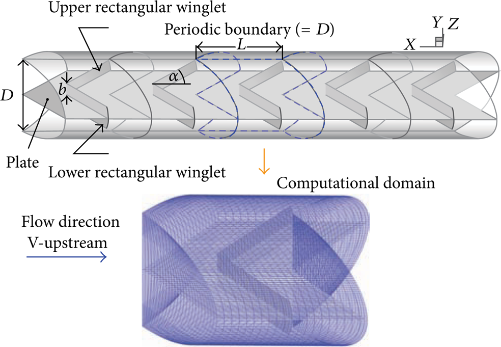
Tested tube geometry and computational domain of periodic flow.
The mathematical form for fluid flow and heat transfer in a round tube was developed under the following assumptions [18–21]:
steady three-dimensional fluid flow and heat transfer,
the flow is laminar and incompressible,
constant fluid properties,
body forces and viscous dissipation are ignored,
negligible radiation heat transfer.
2.2. Boundary Conditions
References [18–21] show that periodic boundaries are used for the inlet and outlet of the flow domain. Constant mass flow rate of air with 300 K (Pr = 0.7) is assumed in the flow direction rather than constant pressure drop due to periodic flow conditions. The inlet and outlet profiles for the velocities must be identical. The physical properties of the air have been assumed to remain constant at average bulk temperature. Impermeable boundary and no-slip wall conditions have been implemented over the tube wall as well as the RWVG. The constant temperature of the circular tube wall is maintained at 310 K while the RWVGplate is assumed at adiabatic wall conditions.
2.3. Governing Equations
References [18–21], based on the above assumptions, show that the tube flow is governed by the continuity, the Navier-Stokes equations, and the energy equation. In the Cartesian tensor system these equations can be written as follows.
Continuity equation:

Momentum equation:

Energy equation:

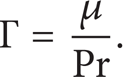
where Γ is the thermal diffusivity and is given by
Apart from the energy equation discretized by the QUICK scheme, the governing equations were discretized by the second order upwind scheme, decoupled with the SIMPLE algorithm and solved using a finite volume approach [22]. The solutions were considered to be converged when the normalized residual values were less than 10−5 for all variables but less than 10−9 only for the energy equation.
2.4. Grid System
References [18–21] show that the computational domain is resolved by regular Cartesian elements. For this tested tube flow, however, regular grid was applied throughout the domain. A grid independence procedure was implemented by using Richardson extrapolation technique over grids with different numbers of cells. The characteristics of four grids: 49,000, 98,000, 196,000, and 392,000 cells are used in the simulations for using the grid convergence index (GCI) [23]. The variation in Nu and f values for the RWVG at BR = 0.15 and Re = 1000 is less than 0.25% when increasing the number of cells from 98,000 to 196,000; thus there is no such advantage in increasing the number of cells beyond this value. Considering both convergent time and solution precision, the grid system of 98,000 cells was adopted for the current computational model at PR = 1 while using 122,500, 147,000, 171,500, and 196,000 cells for PR = 1.25, 1.5, 1.75, and 2, respectively.
3. Calculation of Heat Transfer, Friction Factor, and Thermal Enhancement Factor
References [18–21] show that four parameters of interest in the present work are the Reynolds number (Re), friction factor (f), Nusselt number (Nu), and thermal enhancement factor (TEF). The Reynolds number is defined as

The friction factor, f, is computed by pressure drop, Δp, across the length of the periodic tube, and L as

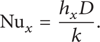
The heat transfer is measured by local Nusselt number which can be written as
The average Nusselt number can be obtained by

The thermal enhancement factor (TEF) is defined as the ratio of the heat transfer coefficient of an augmented surface, h, to that of a smooth surface, h0, at an equal pumping power and is given by

where Nu0 and f0 stand for Nusselt number and friction factor for the smooth tube, respectively.
4. Numerical Result and Discussion
4.1. Validation of Smooth Circular Tube
Figures 2(a) and 2(b) show validation of the heat transfer and friction factor of the smooth round tube without RWVG, respectively, with similar condition. The results show agreement well within ± 0.28% on both Nusselt number and friction factor. The exact solutions of the Nusselt number and the friction factor for laminar flows over smooth tube with constant wall temperature are as follows [24]:


Validation of (a) Nusselt number and (b) friction factor for smooth round tube.
4.2. Flow Topology
The flow visualization in the tested tube with RWVG inserted in the middle of the round tube can be displayed by considering the streamline plots as depicted in Figures 3 to 7. Streamlines in transverse planes and the details of each plane (A1–A5) for RWVG at PR = 1, BR = 0.15, and Re = 1000 are presented in Figures 3(a) and 3(b), respectively, while the PR = 1.25, 1.5, 1.75, and 2 are also present in Figures 4(a), 4(b), 4(c), and 4(d), respectively, at similar BR and Re values.

(a) Streamlines in transverse planes and (b) details of each plane for RWVG at PR = 1, BR = 0.15, and Re = 1000.

Streamlines in transverse planes for RWVG of (a) PR = 1.25, (b) PR = 1.5, (c) PR = 1.75, and (d) PR = 2 at BR = 0.15 and Re = 1000.
As seen in Figure 3, the main four longitudinal vortex flows appear with RWVG inserted through the tested module. Two similar counter-rotating vortices appear on both the upper and the lower parts due to RWVG symmetry as depicted in planes A1 to A5. This vortex flow pattern is similar for the PR = 1.25, 1.5, 1.75, and 2 cases in Figures 4(a), 4(b), 4(c), and 4(d), respectively, but different in the level of vortex strength.
A closer examination exposes that the upstream RWVG produces two counter-vortex flows, the lower part having a rotating direction down to the tube wall, called “common-flow-down.”. The appearance of the vortex flow can help increase higher heat transfer in the tested tube because of highly transporting the fluid from the central core to the near wall regimes.
The flow visualizations in terms of streamline impinging jet on the plate that installed RWVG are shown in Figures 5(a) and 5(b) for various BR and PR, respectively. In these figures, it is apparent that the differences in BR and PR values lead to the distinction in a helical pitch range. The increment of BR and reduction of PR result in the decrease in helical pitch ranges through the tested tube. The case BR = 0.20 shows the shortened while the BR = 0.05 gives a very long helical pitch range before impinging on the plate wall. The effect of PRs, the streamline impinging jets for all PR values perform nearly pattern but different in the helical pitch length. The PR = 1 shows the shortest in the helical pitch range around 3D before impingement and becomes shorter (about 2D) after impingement when PR>1, the helical pitch range provide longer. This indicates that the helical vortex flow passes three RWVG modules from tip to the other winglet trailing edge (WTE) side before impingement. This behavior is identical on both the upper and lower parts.
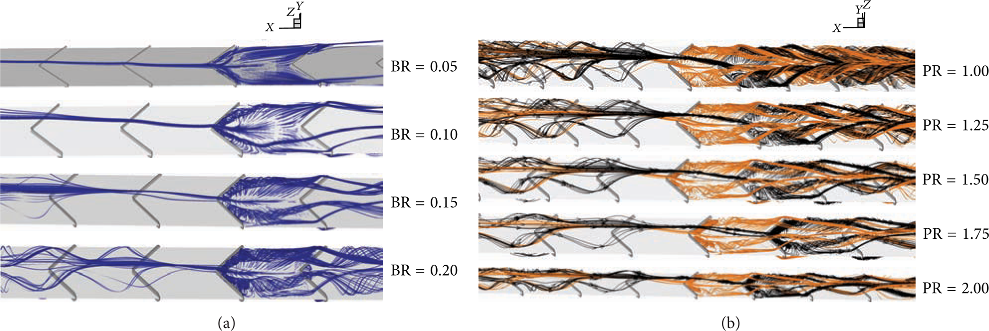
Streamlines of impinging jet between module at (a) various BR for PR = 1.50 and Re = 1000 and (b) various PR for BR = 0.15 and Re = 800 of RWVG.
The streamline jet impinging on the tube wall with the contour of Nu x at PR = 1, BR = 0.15, and Re = 1000 is displayed in Figure 6. As seen in Figure 6, the area of impinging jet shows the highest heat transfer rate than the other zones.
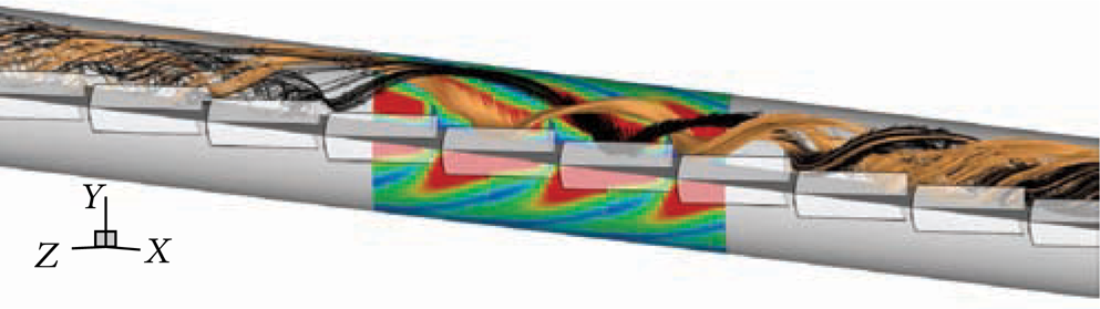
Streamlines of impinging jet on tube wall with contour Nu x for RWVG at BR = 0.15, PR = 1, and Re = 1000.

Contour temperature in transverse planes for RWVG of (a) PR = 1, (b) PR = 1.25, (c) PR = 1.5, (d) PR = 1.75, and (e) PR = 2 at BR = 0.15 and Re = 1000.
4.3. Heat Transfer Characteristics
Figures 7(a), 7(b), 7(c), 7(d), and 7(e) show the contour plot of temperature in transverse planes for RWVG at BR = 0.15 and Re = 1000 at PR = 1, 1.25, 1.5, 1.75, and 2, respectively. These Figures show that there are major changes in the temperature field throughout the round tube. This indicated that the vortex inducing impingement flow provides a significant influence on the temperature field, because it can induce better fluid mixing between the wall and the core flow region, leading to a high temperature gradient over the heating tube wall. The higher temperature gradient can be observed where the flow impinges the tube wall. The impinge area shows that low temperature gradient happens. However, the temperature profiles for all cases are seen to be similar and almost distributed uniformly in the entire flow, indicating excellent mixing of the fluid flow.
Local Nu x contours for the round tube wall with the RWVG at Re = 1000 and BR = 0.15 are presented in Figures 8(a), 8(b), 8(c), 8(d), and 8(e) for PR = 1, 1.25, 1.5, 1.75, and 2, respectively. In these Figures, it appears that the higher Nu x values over the wall are seen in a larger area. The peaks are observed at the impingement areas on the wall near the inserted plate. This shows the advantage of using the RWVG over the smooth circular tube for enhancing heat transfer.

Contour Nu x for RWVG of (a) PR = 1, (b) PR = 1.25, (c) PR = 1.5, (d) PR = 1.75, and (e) PR = 2 at BR = 0.15 and Re = 1000.
The variations of the average Nu/Nu0 ratio with Reynolds number values, BRs, and PRs are depicted in Figure 9(a), 9(b) and 9(c), respectively. It is found that the Nu/Nu0 value tends to increase with the rise of Reynolds number, BRs, and with the decrease in PRs for all cases. The case of BR = 0.20, PR = 1, and Re = 2000 shows the highest heat transfer rate.

Variation of Nu/Nu0 with (a) Reynolds number, (b) BRs, and (c) PRs for RWVG.
Thus, the creation of vortex flows from using the RWVG as well as the role of better fluid mixing and the impingement is the main reason for the augmentation in heat transfer of the tested tube. The use of the RWVG with the Re, BR, and PR range studied yields a heat transfer rate of about 1.0–11.0 times higher than the smooth round tube with no RWVG.
4.4. Pressure Loss
Figures 10(a), 10(b), and 10(c) present the variation of the normalized friction factor ratio, f/f0, with Reynolds number, BRs, and PRs, respectively, for RWVG. As seen in these figures, the f/f0 tends to augment with the rise of Re and BR values and with the reduction of PR for all cases. The use of the RWVG leads to a considerable increase in the friction factor in comparison with the plain tube with no RWVG. The maximum value of f/f0 is found at BR = 0.20, PR = 1, and Re = 2000. The f/f0 values are found to be about 1–105 times over the smooth tube depending on the BR, PR, and Reynolds number values.
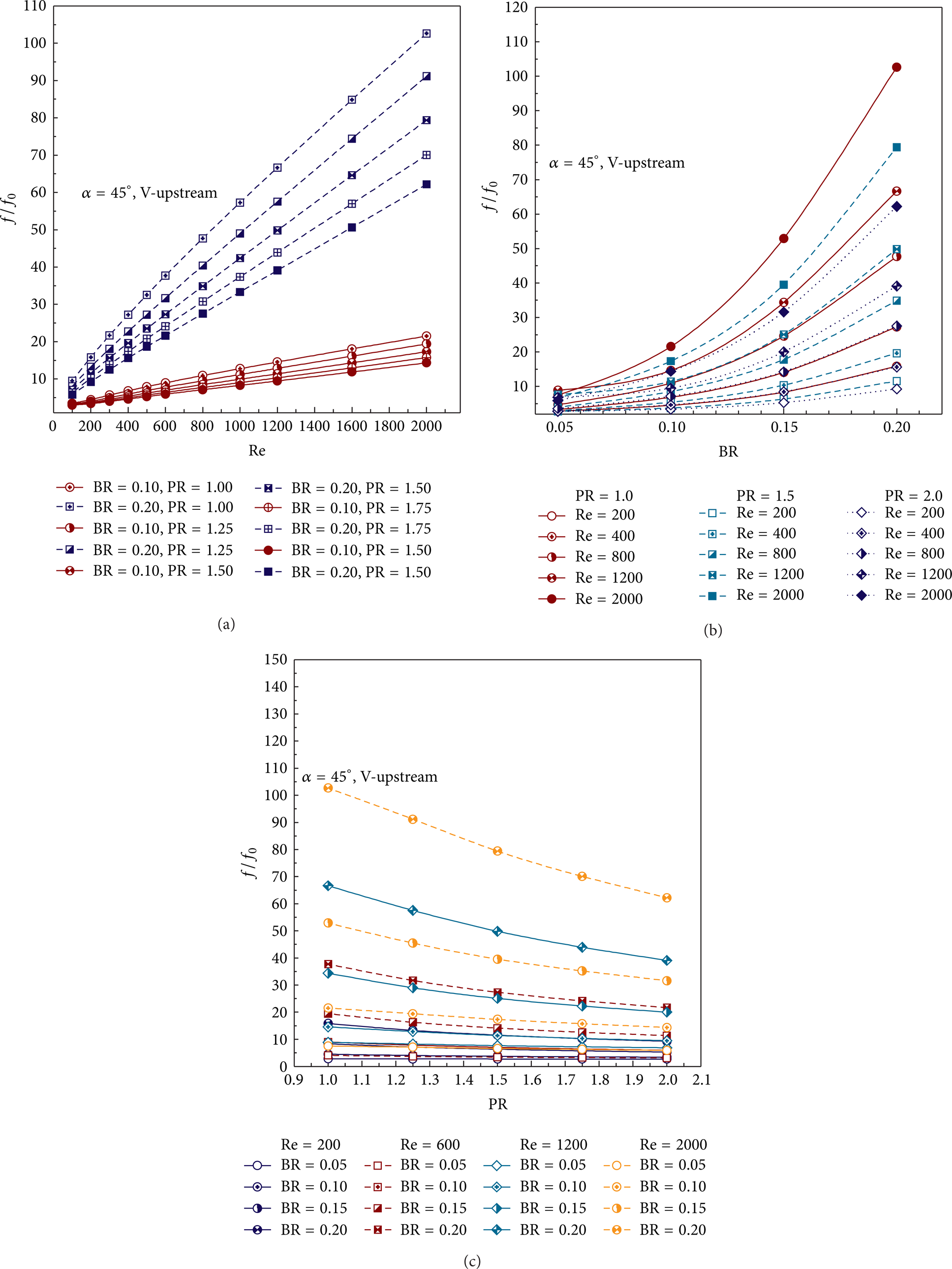
Variation of f/f0 with (a) Reynolds number, (b) BRs, and (c) PRs for RWVG.
4.5. Thermal Enhancement Factor, TEF
Figures 11(a), 11(b), and 11(c) exhibit the variation of thermal enhancement factor (TEF) with Reynolds number, BR, and PR, respectively, for RWVG. In these figures, the enhancement factor of RWVG tends to increase with the rise of Re values for all cases. All of the RWVG provide the highest enhancement factor at the highest Re, Re = 2000. The TEF values are seen to be above unity for all BRs and PRs and vary between 0.9 and 2.9, depending on the BR, PR, and Re values. The maximum TEF is found to be in cases BR = 0.15 at PR = 1.

TEF with (a) Reynolds number, (b) BRs, and (c) PRs for RWVG.
5. Conclusions
In this paper, fully developed periodic laminar flow visualization and heat transfer characteristics in a circular tube fitted with the closed end of RWVG elements in tandem, in-line arrangements on both sides of the inserted plate in the middle of the tested tube have been investigated numerically. The following are the main findings in this paper.
The longitudinal vortex flows created by using the RWVG help induce impingement flows on the tube wall leading to an extreme increase in heat transfer in the round tube.
In ranges studied, the order of heat transfer enhancement is around 100–1100% higher than the smooth round tube for using the RWVG with BR = 0.05–0.20, PR = 1–2, and Re = 100–2000.
The pressure loss is very large, ranging from 1 to 105 times above the smooth round tube.
The thermal enhancement factors for RWVG are found to be in a range of 0.9–2.9 and the maximum TEF is found at BR = 0.15, PR = 1, and Re = 2000.
The variations of BR have influenced much more than the effect of PR values.
Footnotes
Nomenclatures
Conflict of Interests
The authors declare that there is no conflict of interests regarding the publication of this article.
Acknowledgments
The funding of this work is supported by King Mongkut's Institute of Technology Ladkrabang, Thailand. The author would like to thank Associate Professor Dr. Pongjet Promvonge, KMITL, for the suggestions.