
Abstract
Supersonic film cooling is an efficient method to cool the engine with extremely high heat load. In order to study supersonic film cooling in a real advanced engine, a two-dimensional model of the hypersonic inlet in a scramjet engine with supersonic film cooling in the isolator is built and validated through experimental data. The simulation results show that the cooling effect under different coolant injection angles does not show clear differences; a small injection angle can ensure both the cooling effect and good aerodynamic performances (e.g., flow coefficient) of the hypersonic inlet. Under selected coolant injection angle and inlet Mach number, the cooling efficiency increases along with the injection Mach number of the coolant flow, only causing a little total pressure loss in the isolator. Along with the increase of the inlet Mach number of the hypersonic inlet, the cooling efficiency does not present a monotonic change because of the complex shock waves. However, the wall temperature shows a monotonic increase when the inlet Mach number increases. The mass flow rate of coolant flow should be increased to cool the engine more efficiently according to the mass flow rate of the main stream when the inlet Mach number increases.
1. Introduction
Thermal protection is a significant challenge for advanced aeroengines used to power aircraft, rockets, and missiles. In order to protect an engine flying with a high Mach number from being burnt out, regenerative cooling, film cooling, combined cooling, and so forth have been applied to cool the engine [1]. Supersonic film cooling, as one of the most promising cooling methods, has attracted researchers’ attention for its potential usage on scramjet engine, which is one of the engines with extremely high heat load.
Regenerative cooling is the general cooling method in a scramjet engine and there are many challenges when designing the regenerative cooling system. Combined with supersonic film cooling, the difficulties of designing the regenerative cooling system can be largely reduced. On the other hand, supersonic film cooling is very suitable to cool the local area with high heat load.
The advantages of supersonic film cooling have been widely recognized. Many numerical and experimental studies have been carried out. The effect of geometry shape and size of coolant jet holes, the injection Mach number, and blowing ratio of the film on the cooling efficiency has been numerically and experimentally studied [2–4]. Researchers also noticed that the shock waves, which are common in the flow field of a scramjet engine, may have effect on the cooling efficiency. Juhany and Hunt [5] and Kanda et al. [6] have found that the cooling efficiency will be reduced when the shock waves interact with the boundary layer and the research of Peng and Jiang [7] has also indicated the same trend.
However, none of the studies were carried out under real operation parameters and structure parameters of a scramjet engine. In a real engine, the position of the coolant jet holes and the injection angles may have dramatically on the flow field, especially when the jet holes are located at the inlet and isolator. The shock waves in a scramjet engine in a real engine are also very complicated and that makes the supersonic film cooling more complicated. What is more, the main stream used to evaluate the cooling efficiency in most researches is not typical for a scramjet engine.
So, in order to further reveal the cooling efficiency of supersonic film cooling and the practicability of supersonic film cooling in a real scramjet engine, a hypersonic inlet with isolator of scramjet engine is chosen as the study object because of its the complex shock waves. Numerical model in terms of supersonic film cooling is built and validated through experimental results.
In this paper, the effect of injection angle of coolant air on the flow field of the hypersonic inlet with isolator is firstly studied and then the effect of injection Mach number and blowing ratio on the cooling efficiency is investigated. At last, the cooling efficiency of supersonic film cooling at different Mach number of the inlet flow is discussed.
2. Physical Model and Computations
To reflect the real flow field in the scramjet engine, a real hypersonic inlet with isolator from [8] is adopted in this paper, which is listed below. Supersonic film cooling is added to the inlet model and the numerical method used for the supersonic film cooling is the same as that used in [8] and the numerical simulation results were compared with the experimental data in [9]. The comparison showed that the numerical method can predict both the flow field of the hypersonic inlet and the flow characteristics of supersonic film cooling. The details of the numerical method and the validation are listed below.
2.1. Inlet Model with Supersonic Film Cooling and Computations
The main geometric parameters of the hypersonic inlet are referred to in Figure 1 and Table 1, and the length unit is mm, and the angle unit is degree. It is a mixed-compression inlet, including three external shocks and two internal shocks. The compression angle of the three external shocks is 6°, 8.3°, and 9.8°, respectively, and the compression angle of the two external shocks is 10° and 14.1°, respectively, which can guarantee the similar strength of the shock. The external contraction ratio is 5.47, the internal contraction ratio is 1.29, and the total contraction ratio is 7.05. The length of the isolator is seven times the height of the isolator.
Geometric parameters of the hypersonic inlet.


Geometric sketch of the inlet model.
The computation is performed using the Finite-Volume technique with upwind discretization to solve the two-dimensional compressible Reynolds-Averaged Navier-Stokes equations. The air is considered to be a calorically perfect gas. The space discretization is performed by a cell-centered formulation. To account for the directed propagation of information in the inviscid part of the equations, the advection upstream splitting method (AUSM) flux vector splitting is applied for the approximation of the convective flux functions.
SST k-ε turbulence model is implemented for turbulent flows. The boundary condition of the supersonic inflow is far-pressure field, and the freestream conditions can be defined by specifying the boundary conditions. The boundary condition of the exit of the hypersonic inlet is the pressure outlet, and the backpressure can be defined by altering the pressure value. In case of predominant supersonic outflow, the variables are completely extrapolated from the interior to the boundary. Otherwise, the influence of the throttle is simulated with a prescribed backpressure at the outflow boundary and the remaining variables are extrapolated. At solid walls, the no-slip boundary condition is enforced by setting the velocity components to zero. The computations have been performed using the structured grid.
For the computation of the hypersonic flow, it is necessary to construct enough grids to capture the strong shocks. The mesh we used is fine enough to get accurate simulation results according to [8]. In this paper, the inlet Mach number varies from 4 to ∼6 and the boundary conditions of the hypersonic inlet is shown in Table 2.
Boundary conditions of the hypersonic inlet.

Figure 2 shows the temperature distribution of the hypersonic inlet with isolator without cooling. As can be seen from Figure 2, the down wall of the isolator presents a clear high temperature because of the special flow field with complex shock waves interacting with the boundary layers. So, proper cooling is needed for the down wall of the isolator.

Temperature distribution of the hypersonic inlet with isolator without cooling; inlet M0 = 4.
As shown in Figure 3, supersonic film cooling is added into the inlet model through cutting a slot in the down wall of the isolator. The slot is 1 mm wide and the angle of the injected coolant is set to be δ c , which is shown in Figure 3. The air used for supersonic film cooling is subtracted from the air entering the inlet. So, to ensure the aerodynamic performances of the inlet, the mass flow rate of the air used for cooling is limited to be less than 5% of the total mass flow rate of the inlet.

Geometric sketch of the inlet model with supersonic film cooling.
2.2. Numerical Model of Supersonic Film Cooling and Validation
In this paper, the same numerical method is used for the calculation of the supersonic film cooling because the calculations of the hypersonic inlet and the supersonic film cooling are coupled. During the calculation, air is considered to be ideal gas, while the specific heat C p and the thermal conductively λ are got through fitted equations based on the data from NIST database [10] and the viscosity is calculated using the Sutherland model.
The equations to calculate the specific heat and thermal conductivity are listed as follows,

The physical model we used for numerical validation here is the same with that in [8], which is shown in Figure 4. The same boundary conditions are also adopted.
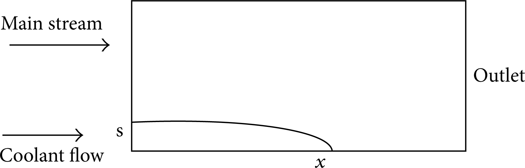
Sketches of the model for numerical validation.
The length of the calculated zone is 2 m and the height of the main stream inlet is 0.2 m. The coolant flow is injected into the calculated zone parallel to the main stream and the height of the coolant flow, s, is in accordance with the experimental data. The main stream and coolant flow are both pressure inlet and the outlet is pressure outlet. All the walls are set to be adiabatic nonslip walls. The boundary conditions of the main stream and coolant flow are given in Table 3.
Boundary conditions of the main stream and coolant flow.

Blowing ratio is always used to present relative value of the coolant mass flow rate in supersonic film cooling and it can be given by

where ρ f ,u f are, respectively, the density and velocity of the injected coolant and the ρ∞, u∞ are the density and velocity of the main stream.
The cooling efficiency of the supersonic film can be given by

where T r∞ , T aw , and T rc , are, respectively the recovery temperature of main stream, the adiabatic wall temperature and the recovery temperature of coolant flow.
As shown in Figure 5, the calculated cooling efficiency of supersonic film is compared with the experimental data from [9] in log-log coordinate. It can be seen from Figure 5 that the calculated results agree with the experimental data well. In Figure 5, Mc is the Mach number of the coolant flow and M is the blowing ratio, which is defined in (2).
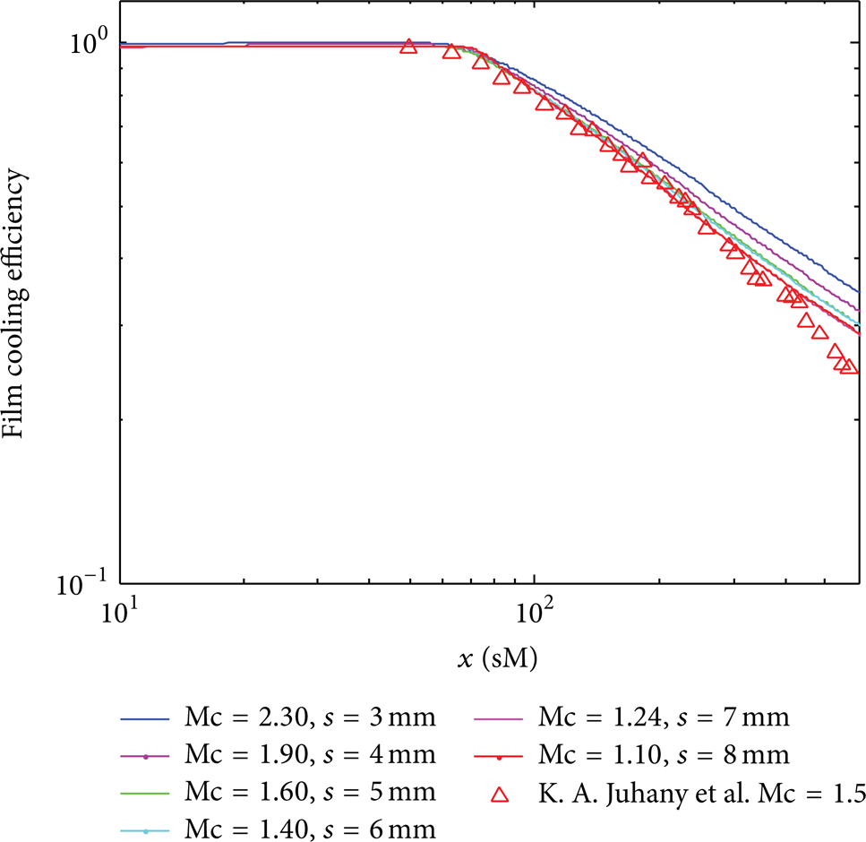
Comparison of supersonic film cooling efficiency between numerical simulation and experimental data.
3. Results and Discussion
For the inlet model with supersonic film cooling at its isolator, which is shown in Figure 3, the injection angle of the coolant flow, the injection Mach number, and blowing ratio are changed to get basic knowledge of the supersonic film cooling under different conditions. After that, a reasonable injection angle and injection Mach number of the coolant flow are selected and the inlet Mach numbers of the hypersonic inlet are changed to see whether the supersonic film can cool the wall of the isolator properly at different inlet Mach numbers.
3.1. Effect of the Injection Angle of the Coolant Flow on the Cooling Efficiency and Flow Field of the Hypersonic Inlet
To see effect of the injection angle of the coolant flow on the cooling efficiency and flow field of the hypersonic inlet, the inlet Mach number of the hypersonic inlet and the injection Mach number of the coolant flow are, respectively, set to be 4 and 2.1; the blowing ratio is 1.153 correspondingly. The static pressure of the coolant flow is set to be the same with the main stream to avoid unnecessary shock waves caused by the coolant flow.
It can be seen from Figure 5 that the supersonic film cooling can efficiently lower the down wall temperature of the isolator and the final mass flow rate of coolant flow, which is 4.12% of the mass flow rate of main stream, is acceptable.
From Figure 6 it can be seen that the cooling effect varies a little when the injection angle increases; however, a large injection angle can cause bad effects on the flow field of the hypersonic inlet. The original pressure and velocity field of the hypersonic inlet without supersonic film cooling are shown in Figure 7, and Figures 8 and 9 are, respectively, the pressure and velocity distributions of the hypersonic inlet at different injection angles of coolant flow. As can be seen in Figures 8 and 9, the flow field of the hypersonic inlet is slightly influenced when the injection angle of the coolant flow is 20°, while along with the increase of the injection angle, the flow field of the hypersonic inlet is dramatically affected and that will cause bad effects on the aerodynamic performances (decrease of the flow coefficient and overall pressure coefficient) of the hypersonic inlet.

Temperature of the down wall of the isolator at different injection angles.
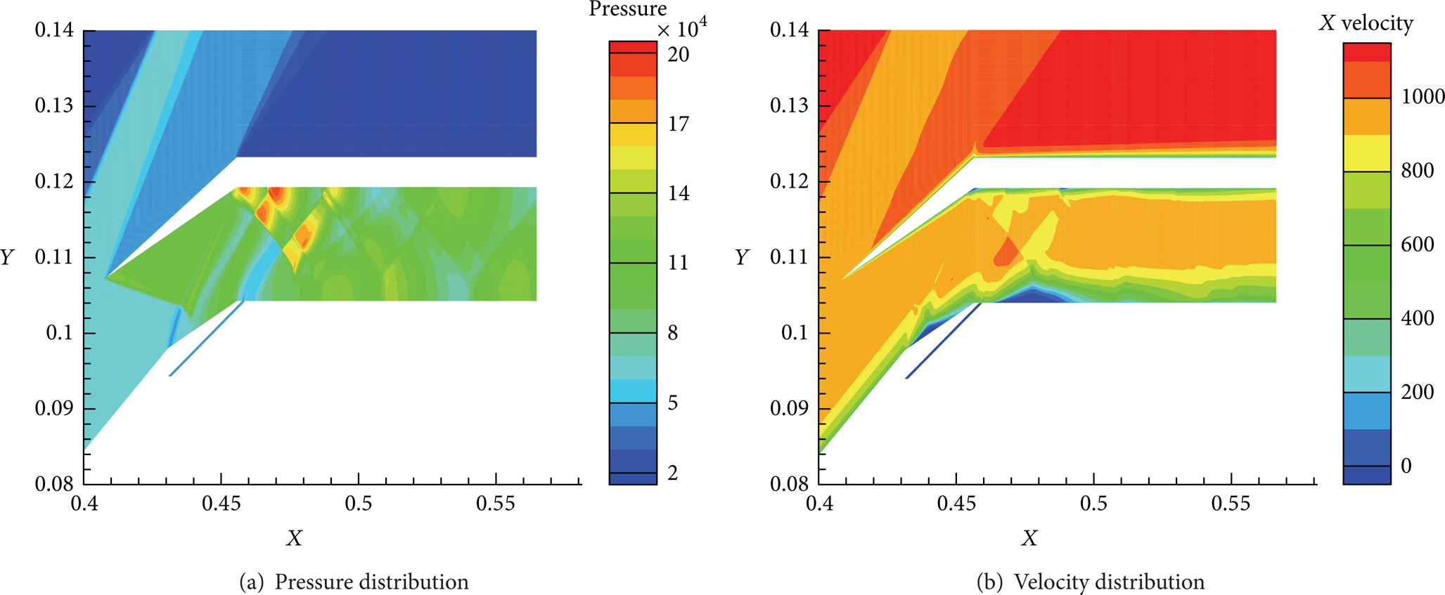
Flow field of the hypersonic inlet with isolator.
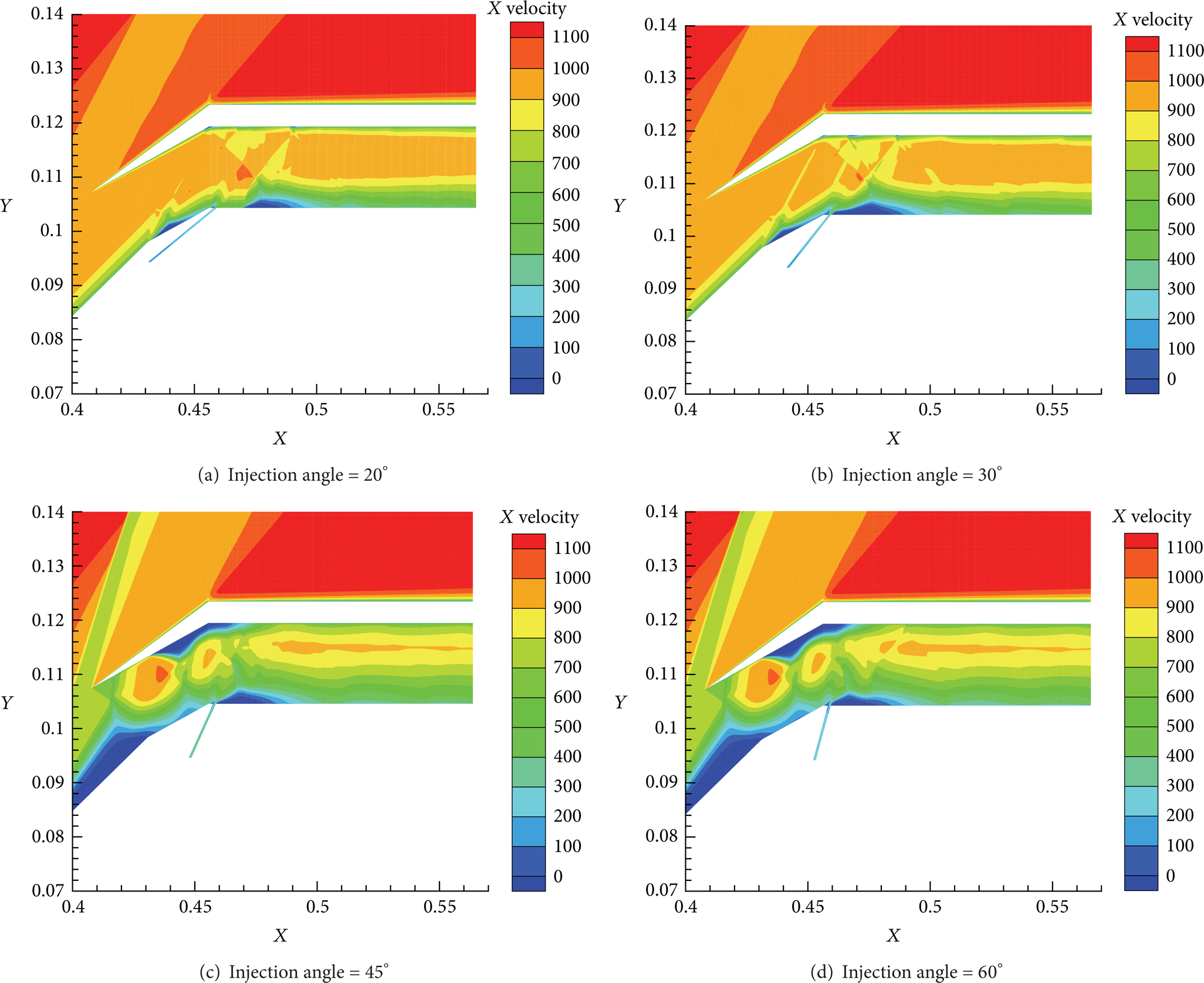
Velocity distributions of the hypersonic inlet with isolator at different injection angles.
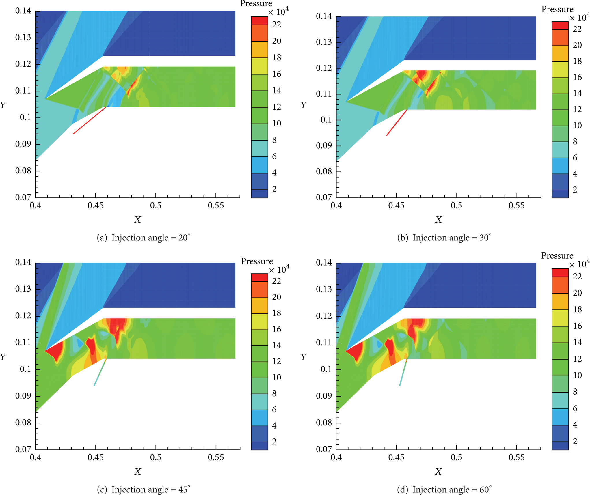
Pressure distributions of the hypersonic inlet with isolator at different injection angles.
From the above analysis, it can be concluded that the supersonic film cooling is an efficient way to cool the wall of the isolator, but the injection angle of the coolant flow should be small enough to avoid bad effects of the large injection angle of the coolant flow on the aerodynamic performances of the hypersonic inlet.
3.2. Cooling Efficiency of Supersonic Film under Different Injection Mach Number and Blowing Ratio of Coolant Flow
To study the cooling efficiency of supersonic film under different injection Mach numbers, the injection angle of the coolant flow is set to be 20° according to the analysis above.
The injection Mach number of the coolant flow varies from 1.14 to 2.1 and the blowing ratio varies from 0.513 to 1.153 correspondingly. The details of the parameters of the coolant flow are listed in Table 4. In the table, mc and mt are respectively the mass flow rates of the coolant flow and the main stream.
Parameters of the coolant flow.

It can be seen from Figure 10 that the cooling efficiency decreases along the wall of the isolator and it is because when the coolant flows through the wall, the main stream keeps mixing with the coolant flow.

Cooling efficiencies of supersonic film cooling at different coolant injection Mach numbers and blowing ratios.
From Figure 10, it is clear that the cooling efficiency increases along with the increment of the injection Mach number and the correspondingly blowing ratio of the coolant flow and that can be explained by Figure 11. As shown in Figure 11, the temperature of the coolant increases very fast when the injection Mach number is small, this is because a lower velocity of the coolant flow will lead to a dramatic mix of the main stream and the coolant flow.

Temperature distributions of the hypersonic inlet with isolator at different injection Mach numbers; injection angle = 20°.
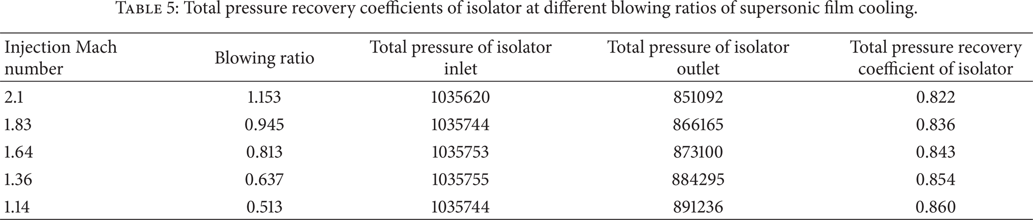
In addition, the effect of the supersonic film cooling on the aerodynamic performances is very important for a good cooling method that should keep the bad effects on the aerodynamic performances minimum. As can be seen in Table 5, the minimum value of the total pressure recovery coefficient of the isolator is 0.822 under all working conditions given in the table, while the total pressure recovery coefficient of the isolator without supersonic cooling is 0.869. So, it can be concluded that the injection Mach numbers of the coolant flow used in this paper are reasonable and the maximum injection Mach number of the coolant flow, which is 2.1, can be adopted.
Total pressure recovery coefficients of isolator at different blowing ratios of supersonic film cooling.
3.3. Cooling Efficiency of Supersonic Film under Different Mach Numbers
From the above analysis, parameters of the coolant flow that can efficiently cool the down wall of the isolator without causing bad effects on the aerodynamic performances of the hypersonic inlet have been selected. Under selected injection angle and Mach number of the coolant flow, which are, respectively, 20° and 2.1, the cooling efficiencies of the supersonic film cooling are evaluated when the Mach number of the hypersonic inlet ranges from 4 to ∼6.
From Figure 12 it can be seen that when the inlet Mach number increases from 4 to 5 or 6, the cooling efficiency decreases. This can be explained by that a higher inlet Mach number will enhance the mixing of the main stream and the coolant flow. However, when the inlet Mach number changes from 5 to 6, the cooling efficiency does not change much firstly and it becomes higher after. This phenomenon can be explained by Figures 13 and 14. From Figures 13 and 14, it can be seen that the low Mach number zone enlarges when the inlet Mach number changes from 5 to 6 and that means a more gender mixing of the main stream and the coolant flow. This mechanism may be caused by the complex shock waves in the hypersonic inlet and should be explored in the future.

Cooling efficiencies of the supersonic film cooling at different Mach numbers of hypersonic inlet.

Mach number distribution of the isolator with inlet Mach number = 5.

Mach number distribution of the isolator with inlet Mach number = 6.
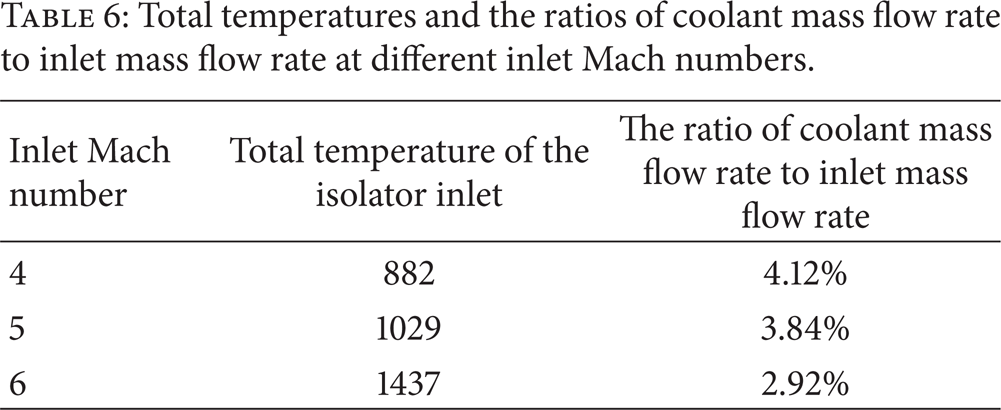
Figure 15 indicates that the wall temperature of the isolator may exceed the allowable temperature when the flying Mach number is 6, even with supersonic film cooling. From Table 6 it can be known that when the inlet Mach number increases, the total temperature and the mass flow rate of the main stream increase, while the mass flow rate of the coolant stays constant. In a real engine, the actual ratio of the coolant mass flow rate to the mass flow rate of the main stream will increase along with the increment of inlet Mach number so that the engine can be efficiently cooled.
Total temperatures and the ratios of coolant mass flow rate to inlet mass flow rate at different inlet Mach numbers.

Temperature distributions of the down wall of the isolator at different inlet Mach numbers.
4. Conclusions
In order to study supersonic film cooling in a real advanced engine, the hypersonic inlet of a scramjet engine is chosen and two-dimensional model of the hypersonic inlet with supersonic film cooling in the isolator is built numerically based on numerical software, Fluent. The model is validated through experimental data. The injection angle of the coolant flow, the injection Mach number, and its corresponding blowing ratio are changed to find reasonable parameters of the coolant flow under limitations in a real engine. The cooling efficiency is studied when the inlet Mach number changes under reasonable parameters of the coolant flow.
The simulation results indicate that if the injection angle of the coolant flow is too large, the aerodynamic performance of the hypersonic inlet will be severely affected. The cooling effect under different injection angles of the coolant flow does not show clear differences; a small injection angle can ensure both the cooling effect and good aerodynamic performances (e.g., flow coefficient, compression ratio, and overall pressure recovery coefficient) of the hypersonic inlet.
Under selected injection angle of the coolant flow and inlet Mach number, the cooling efficiency increases when the injection Mach number of the coolant flow increases and even the highest injection Mach number among the tested cases will only cause a little total pressure loss in the isolator.
Along with the increase of the inlet Mach number of the hypersonic inlet, the cooling efficiency does not present a monotonic change because of the complex shock waves in the hypersonic inlet. However, the wall temperature shows a monotonic increase when the inlet Mach number increases. The mass flow rate of coolant flow should be increased to cool the engine more efficiently according to the mass flow rate of the main stream when the inlet Mach number increases.
The study results have shown that the supersonic film can effectively cool the engine under real limitations brought by the real engine. The effect of the complex shock waves in a real engine on the cooling efficiency should be further studied to better design the supersonic film cooling system.
Conflict of Interests
The authors declare that there is no conflict of interests regarding the publication of this paper.