
Abstract
A multiobjective optimization for improving the turbine output and efficiency of a counterrotating type pump-turbine unit operated at turbine mode was carried out in this work. The blade geometry of both the runners was optimized using a hybrid multiobjective evolutionary algorithm coupled with a surrogate model. Three-dimensional Reynolds-averaged Navier-Stokes equations with the shear stress transport turbulence model were discretized by finite volume approximations and solved on hexahedral grids to analyze the flow in the pump-turbine unit. As major hydrodynamic performance parameters, the turbine output and efficiency were selected as objective functions with two design variables related to the hub profiles of both the runner blades. These objectives were numerically assessed at twelve design points selected by Latin hypercube sampling in the design space. Response surface approximation models for the objectives were constructed based on the objective function values at the design points. A fast nondominated sorting genetic algorithm for the local search coupled with the response surface approximation models was applied to determine the global Pareto-optimal solutions. The trade-off between the two objectives was determined and described with respect to the Pareto-optimal solutions. The results of this work showed that the turbine outputs and efficiencies of optimized pump-turbine units were simultaneously improved in comparison to the reference unit.
1. Introduction
To extract efficiently the renewable energy resources from nature such as hydro, wind, solar, and ocean, there have been increasing interests in the advanced technologies for the power stabilization system in the past several years. However, it is difficult to supply unceasingly the stable power from such nature resources, owing to unforeseen circumstances by an abrupt change in the weather. Thus, the power stabilization system should be certainly advanced to effectively solve the aforementioned problems, with various ideas. Lately, Kanemoto and his colleagues [1–3] have proposed the newly power stabilization system by using the counterrotating type pump-turbine unit with the pumped storage. They demonstrated that this system can instantaneously stabilize the output from the unstable power station with a wind turbine by using the counterrotating type pump-turbine unit. This innovative technology is available for not only the wind power but also all the foregoing renewable energies.
Experimental and computational studies of pump and pump-turbine units with the counterrotating technique have been conducted to understand their internal flow mechanisms and to enhance hydrodynamic performances. The advantages of this counterrotating technique were demonstrated already by many researchers [4–6]. Add to this Kanemoto and Oba [7] have invented the unique double rotational armatures coupled with the counterrotating type impellers or runners to suppress the unstable performance and cavitation throughout the entire operation region. They have called such features “smart control” for thirteen years [8]. Meanwhile, Momosaki et al. [4] performed both the numerical and experimental tests to understand the internal flow structure of contrarotating type axial flow pump rotors, especially the rear rotor. They reported that the unsteady simulation can obtain well more realistic solution as well as to investigate the rotor-rotor interaction. Kasahara et al. [5] discussed the internal flow characteristics at turbine mode of a counterrotating type axial flow pump-turbine unit through numerical analysis. Last, the application of contrarotating type rotors for reducing the rotational speed and/or the pump size under the same specification of conventional axial flow pump was investigated by Cao et al. [9], using experimental and numerical methods.
Although many studies on counterrotating type pump-turbine units have been performed thus far, no attempt has been made to optimize the design of a counterrotating type pump-turbine unit considering simultaneously the multiple hydrodynamic performances. Thus, this study presents a multiobjective optimization procedure for improving hydrodynamic performances of a counterrotating type pump-turbine unit operated at turbine mode based on three-dimensional Reynolds-averaged Navier-Stokes (RANS) analysis. Optimization was conducted to enhance concurrently the turbine output and efficiency of a counterrotating type pump-turbine unit with two design variables related to the hub profiles of both the runners.
The aims of this study are as follows: first, to improve the hydrodynamic performances of a counterrotating type pump-turbine unit operated at turbine mode using the proposed design optimization method; second, to understand the trade-off between the two objective functions with respect to the design variables; and third, to provide practical guideline for the design of the high-performance counterrotating type pump-turbine unit.
2. Counterrotating Type Pump-Turbine Unit
A counterrotating type pump-turbine unit designed from the previous works [8, 11] was considered for the optimization in this work. The counterrotating type pump-turbine unit (Figure 1) consisted of a front impeller (rear runner) with five blades and a rear impeller (front runner) with four blades and operated at a total speed of 1,800 min−1 in this work. In other words, the relative rotational speed between the front and rear runners was kept constant n T = 1,800 rpm. The tip clearances of both the runners were 0.2 mm, respectively; the blade sections were defined by NACA4409 hydrofoil with the single arc camber and thereafter were redesigned numerically by using the commercial computational fluid dynamics (CFD) code to improve the pump performance [11]. The volumetric flow rate and unit output at the best efficiency point were 0.025 m3/s and 5.94 kW, respectively, with the efficiency of 81.26%. The detailed major specifications of this pump-turbine unit were mentioned in [8, 11].

Counterrotating type pump-turbine unit.
In this unit, a new type of the AC induction motor with the double rotational armatures has been developed to operate the counterrotating type impeller (or runner) in place of the traditional type [12]. Namely, the inner and the outer armatures drive the front and the rear impellers, respectively, while the relative rotational speed between both armatures is kept constant and the rotational torque is counterbalanced between both impellers/armatures. Then, the angular momentum change through the front impeller must be the same as that through the rear impeller. Such operating conditions play important parts in adjusting automatically the front and the rear impeller works in response to the discharge and then suppress successfully the unstable operation at the low discharge and the cavitation at the high discharge. Consequently, this unit has fruitful advantages that not only the induced voltage is sufficiently high without supplementary equipment such as a gearbox, but also the rotational moment hardly acts on the mounting bed because rotational torque counterbalances in armatures/runners [12].
3. Numerical Analysis Methods
The flow characteristics through the counterrotating type pump-turbine unit were analyzed by solving three-dimensional incompressible Reynolds-averaged Navier-Stokes (RANS) equations with a k-ω-based shear stress transport (SST) turbulence model [13] using a finite volume solver, the commercial code ANSYS CFX-12.1 [14]. A high-resolution scheme with the specified blend factor value of 1 that is second-order accurate in space was used to solve the convection-diffusion equations. This k-ω-based SST turbulence model is well known to make accurate predictions of flow separations under an adverse pressure gradient [15]. This model uses k-ω and k-ε models in the near-wall region and bulk domain, respectively, and a blending function ensures smooth transitions between these two models. Meanwhile, blade profile creation and computational mesh generation were performed using ANSYS Blade-Gen and Turbo-Grid, respectively. ANSYS CFX-Pre, CFX-Solver, and CFX-Post were used to define boundary conditions, solve governing equations, and postprocess the results, respectively.
The computational domain for the numerical analysis is shown in Figure 2, which consists of each single passage for the two rotational runners of the counterrotating type pump-turbine unit. The flow between two adjacent runner blades was assumed to be periodic in the direction of rotation. The designed normal velocity of 1.689 m/s was set with the turbulence intensity of 5% at the inlet and the averaged static pressure was set at the outlet of the computational domain. Water was considered as the working fluid. The solid surfaces in the computational domain were considered to be hydraulically smooth with adiabatic and no-slip conditions. The periodic boundaries were set at the blade passage interfaces, and the tip clearance was modeled along the blade tip, for the two runners. The stage method [14] which performs a circumferential averaging of the fluxes through bands on the interface was used for the connection between the front and rear runners.

Computational domain and grids.
A hexahedral grid system was constructed in the computational domain with O-type grids near the blade surfaces and H/J/C/L-type grids in other regions, as shown in Figure 2. The grid systems for the front and rear runner domains were constructed using approximately 510,000 and 420,000 grid points, respectively. Here, to benefit from the k-ω-based SST model, the near-wall grid resolution was adjusted to keep y + ≤ 2 to accurately capture the wall shear stress and to implement the low-Reynolds-number SST model [13]. Consequentially, the total grid system has approximately 930,000 grid points for the numerical analysis.
As convergence criteria, the root-mean-square (RMS) values of the residuals of the governing equations were set to less than 10−5 for all equations. The computations were conducted using an Intel Xeon CPU with a clock speed of 3.47 GHz. Here, each calculation was subdivided into four tasks, and data transfer was carried out using MPICH2 [16]. The converged solutions were obtained after 500 iterations and the computational time was approximately 4 hrs.
4. Parametric Study
In the previous work [5], through analyses of the internal flow field at the best efficiency point of the reference pump-turbine unit operated at turbine mode, some losses by the reverse flows were observed in the region of the near hub of both the runners. These losses have an adverse effect on the overall turbine performance of the unit. Therefore, in order to reduce these losses, two geometric variables related to the hub profiles of both the runners were tested to investigate their effects on the pump-turbine's hydrodynamic performances in this work.
An angle β distribution at the hub span of both the runners is changed as shown in Figure 3. Angle β is defined as the angle between the axis of rotation and a tangent of the camber line at the hub span [17, 18]. As the previous works, Kim et al. [17, 18] enhanced successfully the performances of various turbomachines by changing of the β distribution. The entire β distribution changed equally along a runner hub having the fixed meridional geometry, as shown in Figure 3. Here, when the β distribution at each hub was changed equally, the runner blade profiles at other locations were interpolated using a B-spline curve from hub to tip, with the fixed runner profiles at the midspan and tip.

Angle β distribution at hub span of both runner blades.
Sensitivity tests were performed by changing the value of each variable with the other variable fixed at the reference value. Figure 4 shows the results of the turbine output and efficiency through the sensitivity tests of each variable. Here, the value 0 of the x-axis means the unchanged reference angle β. Two variables are generally sensitive to the turbine output and efficiency, as shown in Figure 4. In Figure 4(a), the turbine outputs for the front and rear runners are increased gradually with the decrement and increment of the angle β, respectively. The peak efficiencies for the front and rear runners are distributed at the varied angle β, −4 and 6 degrees, respectively. Especially, the maximum efficiency is shown at the angle β, 6 degree, of the rear runner in Figure 4(b).

Results of sensitivity tests.
5. Multiobjective Optimization Technique
In this work, a multiobjective optimization was conducted for enhancing the multiple hydrodynamic performances of the counterrotating type pump-turbine unit operated at turbine mode. The objective of the present optimization was to simultaneously maximize the turbine output (P11) and the efficiency (η); these were selected as objective functions for the design optimization of the pump-turbine unit. These objective functions are defined as follows:

where P, D, H, ρ, g, and Q denote the output power, diameter of turbine, head, density, acceleration of gravity, and volume flow rate, respectively. To optimize the aforementioned two objective functions simultaneously, a hybrid multiobjective evolutionary algorithm (MOEA) coupled with response surface approximation (RSA) model [19] was applied to obtain the global Pareto-optimal solutions (POSs).
In this work, the aforementioned geometric parameters related to the hub profiles of the two runners were selected as design variables for the optimization to maximize the turbine output and the efficiency of a counterrotating type pump-turbine unit operated at turbine mode. In particular, in design optimization, it is important to find the feasible design space formed by establishing the ranges of the design variables. The ranges of design variables are presented in Table 1, which were determined through the aforementioned parametric sensitivity tests.
Ranges of design variables.

Twelve design points within the design space were selected using Latin hypercube sampling (LHS), which is a design-of-experiment (DOE) method [20]. LHS is an effective sampling method in the design and analysis of computer experiments (DACE) [21]. LHS generates random sample points that ensure that all portions of the design space are represented.
In the present work, as the surrogate model, the RSA model [19] was applied to predict the objective function values in the design space. The RSA model is a methodology of fitting a polynomial function to discrete responses obtained from numerical calculations and represents the association between design variables and response functions. The RSA model can use information collected from various sources and by different tools. The constructed response of a second-order polynomial RSA can be expressed as follows:

where, C, N, and x represent the regression analysis coefficients, the number of design variables, and a set of design variables, respectively, and the number of regression analysis coefficients (C0, C i , etc.) is (N + 1) × (N + 2)/2.
The global POSs were obtained through a hybrid MOEA [22] based on the real-coded NSGA-II developed by Deb [23] for two objective functions: the turbine output and efficiency. Here, “real-coded” means that the crossover and mutations are conducted in real space to obtain a response from the NSGA-II. These POSs are then refined by searching a local optimal solution for each objective function over all NSGA-II-obtained optimal solutions using sequential quadratic programming (SQP) with NSGA-II solutions as initial guesses. The SQP is a gradient-based optimization technique [24] and is a generalization of Newton's method. In this work, one objective was optimized by treating the others as equality constraints, and the local search was repeated for the second objective function by treating the first as an equality constraint [25]. This process resulted in two new sets of optimal solutions that were merged with the NSGA-II solutions. The process of local search improves the quality of the POSs. From these solutions, the first dominated solution was discarded, and subsequent duplicate solutions were removed to obtain the global POSs.
6. Results and Discussion
To verify the accuracy of the numerical analysis, the results of the flow analysis in this work were compared to experimental data performed in the previous work [1]. The reference counterrotating type pump-turbine unit was considered for this validation. Figure 5 shows the performance curve validation results for the turbine output and efficiency of the pump-turbine unit operated at turbine mode [10]. As shown in Figure 5, the numerical results are in good agreement with experimental data across the entire volume flow range. Therefore, it can be seen that the numerical analysis results of this work are valid and reliable.

Validation of the numerical results [10].
To carry out a multiobjective optimization, the RSA models for both objective functions were constructed by using the numerical results at twelve design points selected by LHS. An analysis of variance (ANOVA) and a regression analysis with t-statistics [19] were carried out to measure the uncertainty in the set of coefficients in the polynomial of the response function of the RSA model. Table 2 lists the values of R2 and Radj2 for the second-order curve-fitting and the root mean square error (RMSE) for the RSA model. Here, R2 and Radj2 represent the correlation coefficient in the least squares surface fitting and the adjusted correlation coefficient, respectively. In Table 2, the values of Radj2 for the turbine output and efficiency are 0.996 and 0.956, respectively. As suggested previously by Giunta [26], these values are reliable according to the 0.9<Radj2<1.0 range to evaluate the accurate prediction of the RSA model. Leave-one-out cross validation (CV) errors [27] were also estimated for the RSA models and are listed in Table 2. Consequently, the functional forms of the RSA models for the objective functions can be expressed in terms of the normalized design variables as follows:

Results of ANOVA and regression analysis.

Figure 6 shows the turbine output and efficiency of the global POSs generated by the hybrid MOEA, the clustered optimal solutions (COSs), the evaluations at design points, and the reference design. As objective function values for the turbine output and efficiency are to be maximized, the global POSs show a convex shape, and specifically a trade-off analysis shows an obvious correlation between two objective functions. In other words, a higher efficiency is obtained at a lower turbine output, and vice versa. On the other hand, two objective function values for the global POSs and design points were considerably increased through the multiobjective optimization, in comparison to the reference unit.

Pareto-optimal solutions of multiobjective optimization.
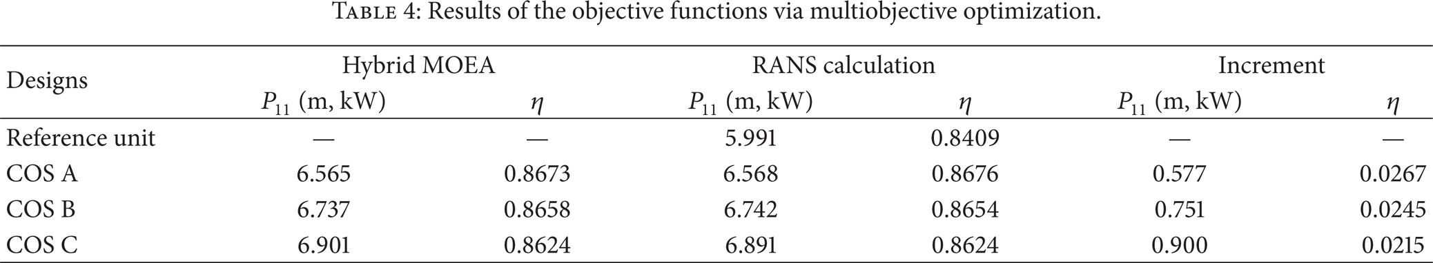
Table 3 lists the values of the optimum design variables for the COSs, and the results of their objective functions are listed in Table 4, along with the reference unit. As shown in Table 3, design variable, β F , tends to decrease, whereas β R tends to increase as the point moves from A to C as shown in Figure 6. In a trade-off of two design variables, specifically they show an obvious opposite relation. Furthermore, two optimum design variables were changed remarkably compared to the reference values. In comparison to the reference unit, both the turbine output and efficiency were noticeably improved in all the COSs, as shown in Table 4 and Figure 7. As the point moves from A to C, the turbine output increases while the efficiency decreases. Hence, COSs A and C represent the designs with the highest efficiency and turbine output, respectively, in the COSs. Consequentially, the results for COSs A and C show improvements in the turbine output by 0.577 and 0.900 m, kW, respectively, and improvements in the efficiency by 0.0267 and 0.0215, respectively, compared to the values for the reference unit, as shown in Table 4 and Figure 7.
Results of the design variables via multiobjective optimization.

Results of the objective functions via multiobjective optimization.
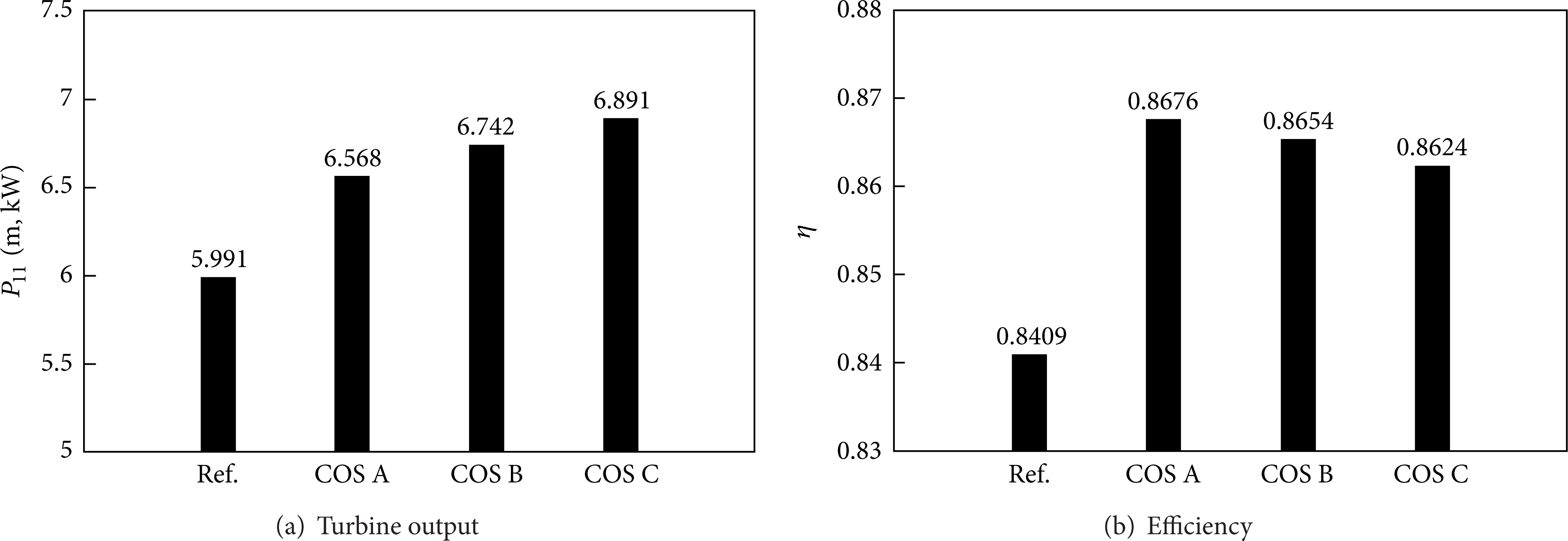
Results of multiobjective optimization.
To investigate the main factors responsible for improving the pump-turbine unit's hydrodynamic performance, the internal flow fields of representative COSs A, B, and C in the global POSs were analyzed and compared to the reference unit. Figure 8 shows the isosurfaces having a reverse flow of 0.1 m/s. As mentioned already, these reverse flows as the negative velocity have an adverse effect on the overall hydrodynamic turbine performance of the pump-turbine unit. As shown in Figure 8, an extensive reverse flow region formed on the hub between the two runners of the reference unit, whereas a similar reverse flow isosurface disappeared clearly in all the COSs. On the contrary to this, the reverse flows at the trailing edge near the suction side of the rear runner in all the COSs were increased slightly compared to the reference unit. However, it can be ignored relatively in comparison to the clear suppression of such extensive reverse flow region. On the other hand, small reverse flow components still occur near the downstream of 90% span in the front runners of all designs including the reference unit.

Isosurfaces with reverse flow of 0.1 m/s.
The velocity vectors near the hub span for the reference unit and all the COSs are plotted in Figure 9. In the reference unit, the reverse flow zone occurred on the suction side downstream of front runner. In particular, the extensive reverse flow occupying the entire blade-to-blade passage occurred on the upstream region of the reference rear runner. Specifically, the velocity vectors in the upstream region of the rear runner are moved to the leading edge of next runner blade, and eventually the extensive reverse flow zone was formed in the entire blade-to-blade passage, as shown in Figure 8(a). In contrast, these reverse flows were reduced generally in the all COSs, and above all the main flow was stabilized substantially near the upstream region of the rear runner. Moreover, the reverse flows near the suction side downstream of their front runners were decreased in comparison to the reference unit, as shown in Figures 9(b)–9(d).

Velocity vectors near hub span (unit: m/s).
Figure 10 shows the streamlines near the hub of the rear runner for the reference unit and all the COSs. In comparison to the reference unit, the streamlines in all the COSs were stabilized significantly in the leading edge region of the rear runner, as shown in Figure 10. Therefore, the COSs produced mostly stable flows in the downstream passage by the optimization.

Streamlines near hub of the rear runner.
Figure 11 shows the pressure distribution in the streamwise direction at the hub span on the suction and pressure sides of the rear runner for the reference unit and all the COSs. As shown in Figure 11, the pressure rise between the pressure and suction sides of the rear runner for all the COSs was enhanced in comparison to the reference unit, and especially at the suction side of the rear runner. These highlight the considerable increase in the hydrodynamic performance of the turbine output and efficiency in the counterrotating type pump-turbine unit as a result of the optimization.

Pressure distribution at hub span of the rear runner.
7. Concluding Remarks
The geometry related to the blade hub profiles of the two runners in a counterrotating type pump-turbine unit operated at turbine mode was optimized using a hybrid MOEA and RSA model through three-dimensional RANS analysis. Optimization was carried out to enhance both the turbine output and efficiency with two design variables related to the blade hub geometry of the two runners. The highest increments of the turbine output and efficiency achieved by the global POSs through multiobjective optimization were 0.900 m, kW and 0.0267, respectively. Through analyses of the flow field in the reference pump-turbine unit at the best efficiency point, it was found that an extensive reverse flow region formed on the hub between the two runners. This reverse flow as the negative velocity had an adverse effect on the overall hydrodynamic performance of the pump-turbine unit. However, the similar reverse flow disappeared clearly in all the COSs produced through the multiobjective optimization. This contributed to considerable increase in the hydrodynamic performance in the optimized pump-turbine units. On the basis of the present results, the multiobjective optimization work for enhancing the hydrodynamic performance at not only the turbine mode but also the pumping mode will be performed in the near future.
Conflict of Interests
The authors declare that there is no conflict of interests regarding the publication of this paper.
Footnotes
Acknowledgment
This work was supported by the SEED Research Project Grant in the Korea Institute of Industrial Technology (KITECH) funded by the Korean government (MSIP) (no. PER14100). The authors gratefully acknowledge this support.