
Abstract
Selecting one IS 150-125-250 centrifugal pump as reference model, impeller with 3D blades has been designed using two-dimensional theory. Numerical simulations using Reynolds averaged N-S equations with a RNG k-ε two-equation turbulence model and log-law wall function are used to estimate the hydraulic performance of pump and obtain BVF distributions on impeller blade pressure surfaces and suction surfaces. The results show that, compared with IS150-125-250 pump, the designed one shows better performance in a wide operation range with the maximal efficiency 2.8% increase. With the help of boundary vorticity flux diagnostic, further improvement is realized. Local defect areas on blade surfaces are identified and inlet blade angle distribution modification and wrapping angle change of designed impeller are carried out on local defect areas. The vortices that exist in designed impeller disappear after modification and it flows more smoothly in the modified impeller with slight hydraulic performance improvement than in the original designed one. BVF diagnostic can be further embedded in optimal design method to perform an automatic optimal design without manual trial-and-error procedures.
1. Introduction
Centrifugal pump has extensive applications in industry and other technical sectors because of its design simplicity, high efficiency, smooth flow rate, and ease of operation and maintenance. Among all the installed pumps in a typical petroleum plant, almost 80–90% of pumps are of the centrifugal type. Design processes of traditional impeller design methods, which are mainly based on the similarity theory, empirical correction, model tests and engineering experience, are difficult tasks mainly due to the great number of free geometric parameters. And these manual processes are often time-consuming. Normally multiple “trial and error” procedures are needed to identify the right combination for the best solution to minimize the effects of local design defect.
With the purpose of deepening the knowledge of relationship between geometric structure of centrifugal pump impeller and the internal flow field in its impeller channels, the local vortex dynamics diagnostic theory is introduced and boundary vorticity flux (BVF) is used to diagnosis the flow in impeller channels. BVF measures the vorticity creation rate from solid surface and enables significant focusing to localized key regions, and the theory shows that the total force and moment can be cast to proper surface integrals of BVF no matter how complicated the vorticity evolution [1–3]. Since the mid-1980s, Wu et al. have established a theory of boundary vorticity dynamics and successfully applied this theory in the aerodynamic diagnosis and optimization of airfoil profile [4]. Zhaohui has diagnosed the flow field of high speed centrifugal pump with BVF method and caught the dramatic change of BVF in the corresponding position of cracks on the inducer blades [5]. Yang et al. analyzed the bidirectional flow in a pump-turbine runner with BVF method and got an optimized blade [6]. Yao et al. optimized the impeller by adjusting the geometrical parameters and modifying the meridional shape of the blade based on BVF method, and the hydraulic performance of the pump was improved [7]. Wu Z et al. have reviewed vortex dynamics theory with emphasis on its physical background and demonstrated its applications [8]. Zhang et al. fully used the advantage of BVF to detect the area during blade design and modify the blade profile under the guide of flow theory of impeller [9]. Compared with the traditional framework analyses of velocity fields and pressure fields, BVF diagnostic has the advantage of obvious amplification of local unwanted flow.
Since no simple mathematic model can be established to well predict the performance of impellers at present and by using numerical procedures, it is possible to predict the performance curve of impellers with enough accuracy and compute the flow field inside the impeller; the BVF distribution in impeller can be easily obtained with the help of computational fluid dynamics technology.
In this paper, IS 150-125-250 centrifugal pump is used as reference model, and one impeller has been designed using two-dimensional theory. Numerical simulations are used to calculate the BVF distributions on impeller blade pressure surfaces and suction surfaces, and modifications of designed impeller are carried out on local defect areas. The effect of improvement of the impeller is verified by numerical simulation and test.
2. BVF Diagnostic Method
Boundary vorticity flux (BVF) is a key concept of the boundary vorticity dynamics theory, and it was first introduced by Lighthill in 1963 as the measure of vorticity creation rate from a body surface ∂B per unit area in a unit time and was defined as [10]
where
For a viscous compressible flow over an arbitrary body surface, the boundary vorticity flux

where

When it comes to centrifugal pump under steady operation condition, it is reasonable to assume that the rotate speed is constant, fluid medium is incompressible, the solid boundaries are no-slip wall, and volume force can be neglected. At large Reynolds number conditions, the effect of explicit viscous terms is a few orders smaller than that of tangent pressure gradient and it is sufficient to focus only on the component

When the Reynolds number is large enough (it usually happens in the flow of impeller passages) it can be well estimated. Any changes in the location and magnitude of BVF distribution can be accounted as redistribution of pressure on surfaces.
The torque on blade can be obtained by BVF integration strictly through derivative moment theory of any domain set by Wu et al. [12]. Consider
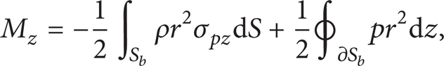
where S
b
indicates blade surface, ∂S
b
is the boundary line of the said blade surface, r is the radius, and σ
pz
is the axial component of
In incompressible flow field the undesired BVF distribution that is the primary cause of the creation and diffusion of the vorticity may cause adverse flow such as boundary layer separation, secondary flows, or large-scale separation flow. Therefore, improvement of impeller blades can be realized by modifying the local defect areas to change the BVF distribution on their blade surfaces.
3. Centrifugal Pump Original Model and Numerical Simulation
The original impeller of a centrifugal pump has been designed using in-house code, which is based on hypothesis of two-dimension theory and the working medium is considered as inviscid and incompressible fluid. Some more details on design procedure can be seen in [13, 14]. According to the desired operating conditions (usually capacity, head, and rotate speed), the basic geometrical features of the initial impeller (such as D1, D2, B2, and Z) can be determined by empirical correlations which are based on the method of velocity coefficient. The parameters are listed in Table 1 and the model of designed pump is shown in Figure 1.
Parameters of designed centrifugal pump impeller.


The model of designed pump.
The calculation domain is mainly composed of inlet extension, impeller, volute, and outlet extension. Reasonable lengths of inlet and outlet extensions are added to the real machine geometry to reduce the unavoidable effect of inlet and outlet boundaries on the final flow solution as a result of the boundary conditions (the length of inlet extension is 4 times of impeller eye diameters and outlet extension is 8 times of outlet tube diameter).
The discretization of the calculation domain is done keeping the balance between calculation time and the accuracy order of the simulation of the flow structure by the ANSYS ICEM preprocess code, and unstructured hexahedra with strong flexibility are used to define the impeller domains. After grid independence analysis, approximately 5.68 million grids of computational domain are chosen to be used in calculation: 3.72 million impeller grids, 1.42 million volute and outlet extension grids, and 0.54 million inlet extension grids. The computational grids are shown in Figure 2.

Computational domain and grids of designed pump.
The fully 3D turbulent flow fields of centrifugal pump are solved by commercial ANSYS FLUENT code. Assuming that the fluid is steady, viscous, and incompressible, the simulation is conducted by applying mass conservation equations, Reynolds averaged Navier-stokes equations, and the RNG k-ε turbulent model and multiple reference frame (MRF) model is applied to take into account the interaction between stationary volute and rotating impeller. For such calculations, wall functions based on the logarithmic law have been used. The pressure-velocity coupling is calculated through the SIMPLEC algorithm, PRESTO! (PREssure STaggering Option) scheme has been used for pressure terms, and second-order upwind discretizations have been used for convection terms.
The type of inlet boundary condition is velocity inlet and it is assumed as a uniform velocity distribution at this plane. The magnitudes of the velocity vectors are computed from the specified mass flow rate. For outlet, the outflow is given as boundary condition. Interface pairs are set between the stationary and rotational regions. The solid wall such as blade surface, hub, and shroud is given the moving wall and others are given the stationary wall. Nonslip conditions have been imposed over all wall boundaries. The operation condition of impeller (Flow rate) can be changed through modifying the axis velocity magnitude at inlet boundary. Water is used as working fluid in ambient condition.
The test rig has also been set up to study hydraulic performance of pump, as it shown in Figure 3. The numerical results obtained with the settings mentioned above and test results of IS 150-125-250 centrifugal pump have been compared to verify the reliability of these numerical simulation settings, as it shown in Figure 4. It can be seen that the hydraulic performance curves agree well with the experimental ones and the relative error is within 1%. And the hydraulic performances of the designed pump are also presented, which are obtained with the same setting. It shows that the performance of designed one is better than IS 150-125-250, with 2.8% maximal hydraulic efficiency increasing.
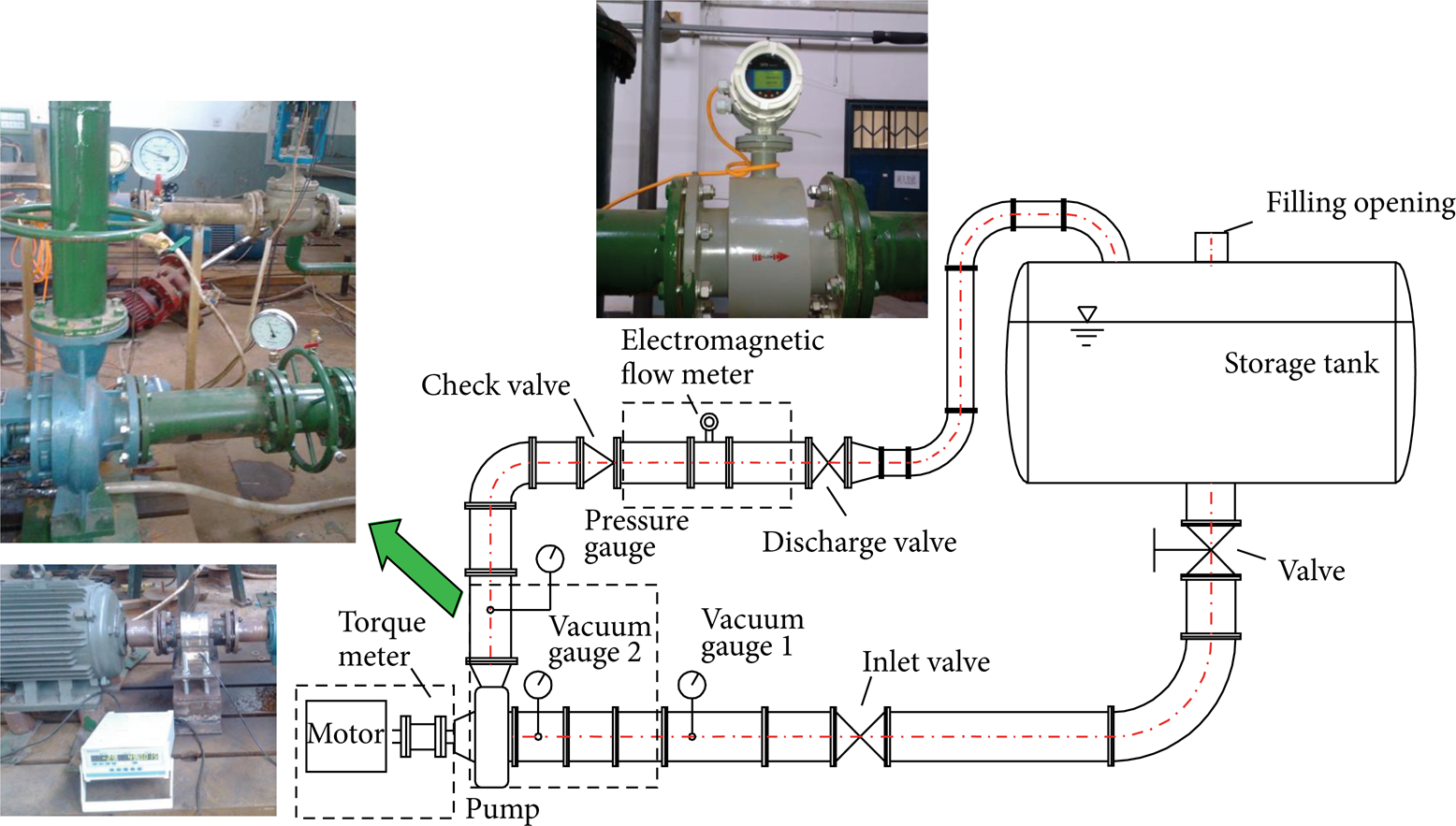
Hydraulic performance test rig of centrifugal pump.

Hydraulic performance curves of the IS 150-125-250 centrifugal pump and designed pump.
4. BVF Diagnostic on Blades
BVF analysis is introduced to diagnose the local key regions on the designed impeller surfaces to locate defect areas. After numerical simulation the data of inner flow fields will be obtained, and then the BVF z distribution of pressure surface and suction surface of blade can be calculated using the expressions mentioned above. The BVF z distributions on pressure side and suction side of designed blade are shown in Figure 5.
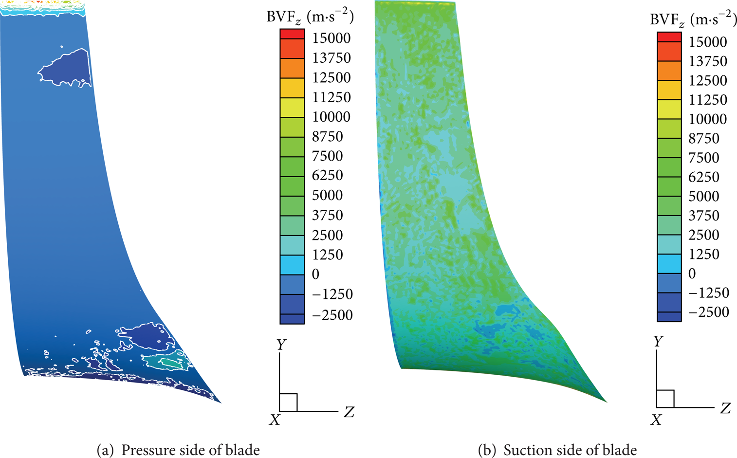
BVF z distribution on the designed blade surfaces.
From Figure 5, it can be seen that the positive BVF z peak value locates at the blade trailing edge region and the large pressure gradient values are near the inlet and outlet regions. The negative BVF z peaks locate at local region on pressure surface near leading edge and trailing edge. And there is alternate area of positive peak and negative peak on pressure side near trailing edge, while BVF z distribution of other areas is uniform. The positive BVF z peak on suction surface locates at trailing edge region of blade, and the negative BVF z area is a little smaller than that on pressure surface.
According to the above BVF analyses of blade, vortices may exist near trailing and leading edge regions of blade, where there is an alternate area of positive peak and negative peak. Two axial sections of impeller are set on these positions as it is shown in Figure 6 for better analysis of the flow field. The relative velocity and pressure distributions on these two sections are presented in Figures 7 and 8.

The position of cross-sections.

Relative velocity distribution and streamline on cross-section 1.

Relative velocity distribution and streamline on cross-section 2.
As it can be seen from streamlines in Figure 7, there is a small scale of axial vortex near blade pressure side in the borderline region on cross-section 1 (its position is shown in Figure 6) which means that flow separation exists at this position on pressure surface. It will reduce the flow passage area which may bring more losses because of the rising of flow velocity and will also cause energy losses due to viscosity of flow medium. From Figure 8, it can be clearly seen that there is a large low relative velocity area near the pressure side and a larger axial vortex at the exit in the impeller channel on cross-section 2 (its position is shown in Figure 6), which will also induce large energy losses. These two vortices have the same position of BVF peak on pressure surface of blade, which reflects that it will be a much better way to analysis the flow in impeller by using BVF diagnostic, in which only the flow fields on blade surfaces are needed. And the local designed defect can be easily caught, which will assist in the improvement of blade design.
5. Profile Modification
After targeting local defect regions on blade surfaces by using BVF diagnostic, it will be very convenient to modify the shape of blade locally to realize an improved design, with the help of ANSYS BladeGen code.
5.1. Blade Inlet Modification
According to above BVF diagnostic, modifications need to be made around blade inlet where the small alternate area of positive peak and negative peak exists. The profile of meridional flow passage is shown in Figure 9, where R represents the coordinate of the radial direction and Z is the coordinate of the axial direction. Five streamlines (including one for hub profile line and one for shroud profile line) are used to divide the flow passage into four parts. These streamlines are numbered from 1 to 5 from hub to shroud.

Meridional flow passage.
The blade angle distributions along these five meridional streamlines are shown in Figure 10, where the horizontal coordinate means the relative meridional streamline lengths and the vertical coordinate is the blade angle value at this position; span 0.0000 represents the streamline at hub (streamline number 1), span 1.0000 represents the streamline at shroud (streamline number 5), and Data 00, Data 01, and Data 02 represent streamlines number 2, number 3, and number 4. It can be seen from Figure 10 that besides streamline number 5 the blade angle distributions along other 4 streamlines are similar. On streamline number 5 it has sharp rising of blade angle at inlet section of blade and its inlet blade angle is relatively small (18°) where the vortex occurs. The reason is that the flow angle near the shroud on the pressure is relatively large and the blade angle is not large enough that negative incidence angle appears which will cause flow separation at blade pressure side easily.
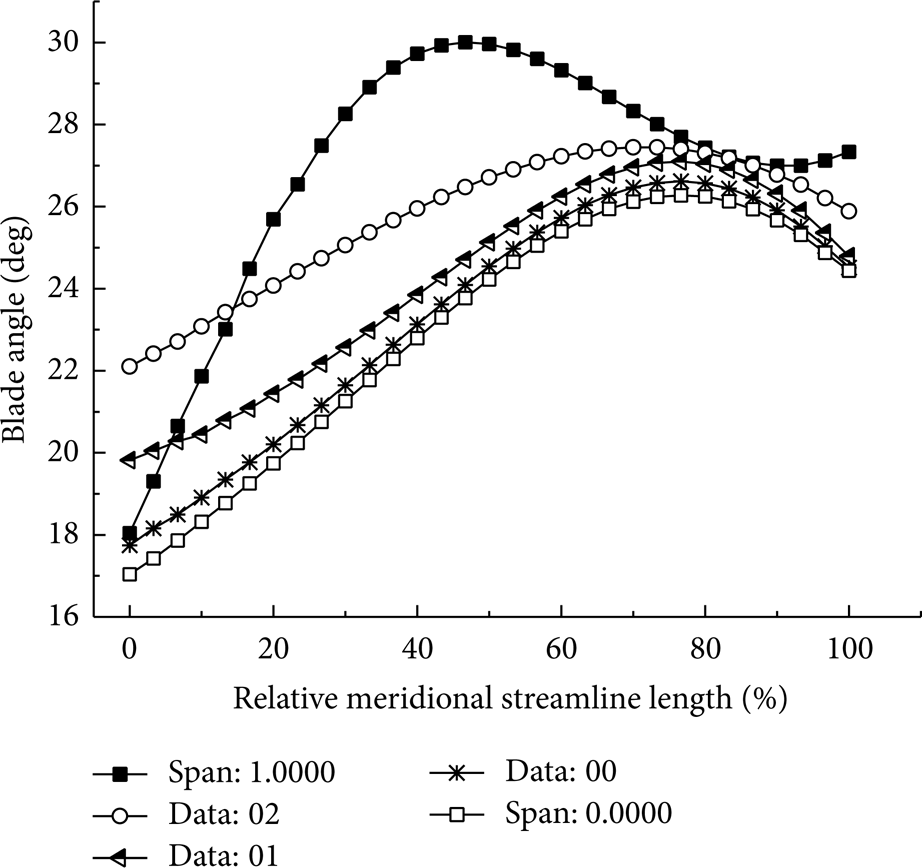
Blade angle distributions along meridional streamlines.
With the consideration of enlarging the inlet blade angle on streamline number 5, the designed blade has been modified by increasing the inlet blade angle by 5° to obtain a new impeller, IMP1. The blade angle distributions of IMP1 are shown in Figure 11. It can be clearly seen that, unlike original designed impeller, the blade angle distributions along these 5 streamlines show similar change and the inlet blade angle is increased to 23°, which will have better effect on impeller performance.

Beta angle change along meridional streamline of IMP1.
The hydraulic performance of IMP1 impeller at operation condition is calculated by numerical simulation and tests, and the comparison of original designed impeller and IMP1 one is listed in Table 2. With only a little change of blade angle distribution on streamline number 5 of blade, its performance is slightly improved.
Numericalcalculation results of original designed pump and the first modified pump.

The comparison of BVF distributions on original impeller and IMP1 one is shown in Figure 12. It can be seen that the area of BVF peak decreases, but it still exists. The reason is that there will be some other factors that contribute to the BVF peak value generation besides the effect of negative incidence angle. By analyzing the relative velocity distribution on blade pressure surface (shown in Figure 13), the back flow happens near hub. It is caused by centrifugal effect when flow changes from axial direction to radial direction, which can be reduced by decreasing the radius of hub profile line.
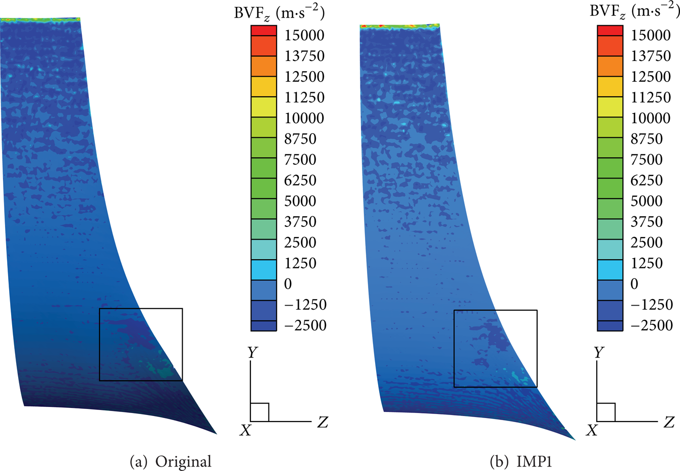
The comparison of BVF z distributions on the pressure sides.
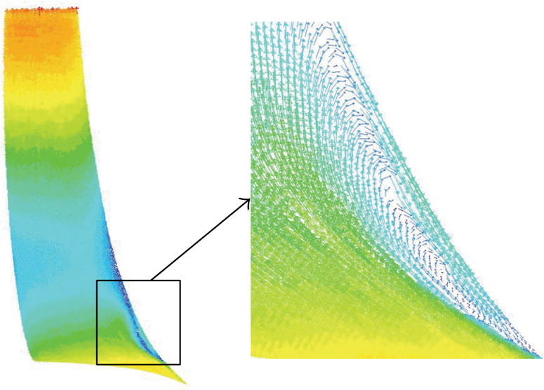
Relative velocity distribution on the pressure side of IMP1.
5.2. Blade Outlet Modification
The large scale of vortex at outlet of blade can be reduced by increasing the wrapping angle of blade to realize a better flow control [15, 16]. IMP1 impeller is used as a base model, and IMP2 one is produced from increasing the wrapping angle of IMP1 blade by 5°, which is carried out by changing the blade angle of blade at middle section and keeping blade angles at the inlet and outlet the same as before. The blade angle distributions along 5 streamlines of IMP2 impeller blade are shown in Figure 14. Different from IMP1 impeller, the blade angles increase gradually along the streamlines and the largest blade angle on each streamline is at the outlet.

Beta angle distribution along meridional streamline of IMP2.
The hydraulic performance of IMP2 impeller at operation condition is calculated by numerical simulation and tests, and the comparisons of original designed impeller and IMP1 one are listed in Table 3. The test result of hydraulic efficiency of IMP2 rises by 0.67%, compared with IMP1 impeller. The blade with larger wrapping angle will have better control of flow to prevent flow separation, while larger wrapping angle will also bring about much disk friction loss. The optimum wrapping angle should be obtained keeping the balance between flow control and friction loss.
Numerical calculation results of the first modified pump and the second modified pump.

From the relative velocity distribution and relative streamlines on IMP2 impeller section in Figure 15, it can be seen that the small vortex near the blade inlet and the large vortex near the blade outlet disappear, and it shows better flow field in flow channels. With the increase of only small blade angles, the shape of blades change but not so much and this change will improve local flow field, while contributing only a small part in whole hydraulic performance. The improvement of local flow filed may show good cavitation performance, because it eases local peak pressure areas on blade surfaces. And it still needs some further tests and analysis work to verify it.
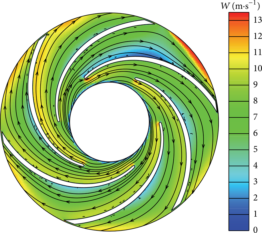
Relative velocity distribution and streamline.
6. Conclusion
Compared with the standard centrifugal pump IS 150-125-250, the performance of designed one, which is designed adopting two-dimension theory, shows better hydraulic performance than IS 150-125-250, with 2.8% maximal hydraulic efficiency increasing.
Through BVF diagnostic the defect areas on blade surface can be easily caught, which is realized by identifying the position of BVF peak and modification can be applied to these areas to improve the flow field in impeller channels and to slightly enhance hydraulic performance of impeller.
According to these different detected BVF peak areas, inlet blade angel increasing and blade wrapping angle increasing are used. The flow fields of these impellers have been calculated by numerical simulation and the results show that, after modification, vortices disappeared. The simulation and test results show that the hydraulic efficiency of pump increases.
Conflict of Interests
The authors declare that there is no conflict of interests regarding the publication of this paper.
Footnotes
Acknowledgments
This research was supported by Petro-China Innovation Foundation (2012 D-5006-0611) and Science Foundation of China University of Petroleum, Beijing (no. KYJJ 2012-04-11). The supports are highly appreciated.