
Abstract
Modern gas turbine blade is operating at high temperature which requires abundant cooling. Considering both heat transfer rate and pumping power for internal passages, developing efficient cooling passages is of great importance. Ribbed channel has been proved as effective heat transfer enhancement technology for considerable heat transfer characteristics; however, the pressure loss is impressive. Dimple and protrusion are frequently considered as new heat transfer augmentation tools for their low friction loss in recent years. Numerical simulations are adopted to investigate the thermal performance of rectangular channel with compound heat transfer enhancement structures with ribs, dimples, and protrusions. Among all configurations, the nondimensional dimple/protrusion depths are 0.2. The results present the flow structures of all channel configurations. The Nu/Nu0 distributions of channel section are discussed for each case. The pressure penalty f/f0 and the thermal performance TP are also considered as important parameters for heat transfer enhancement. It can be concluded that the optimal structure of the compound heat transfer enhancement structure is rib + protrusion (D = 6 mm) + dimple (D = 15 mm).
1. Introduction
Heat transfer enhancement in coolant channel is of great interest and importance in many industrial applications such as gas turbines, heat exchangers, and many cooling devices because higher heat transfer rates increase system efficiency and reduce thermal load. From heat transfer theory, we know that air-side heat transfer enhancement plays a critical role in the design of the heat exchangers. Therefore, many techniques such as rib turbulators, pin arrays, arrays of shaped roughness elements, and dimples have been used in practical systems and many studies have been conducted on them. Xie and his partners [1–4] have made a large amount of research on thermal performance in differently shaped microchannel heat sinks or with different flow pattern.
The rib turbulators break the laminar sublayer and create local wall turbulence due to flow separation and reattachment between the ribs, greatly enhancing the heat transfer. Several researchers have studied the heat transfer and friction characteristics in straight channels. Han and his partners [5–11] have made a large amount of research in this area; they studied the effects of flow Reynolds number and rib geometry on heat transfer and pressure drop in the fully developed region of a uniformly heated square and rectangular channels and showed that angled ribs provide better heat transfer enhancement than transverse ribs. Ekkad and Han [12] have studied the detailed heat transfer distributions in two-pass square channels with rib turbulators and the detailed distributions provide a clear understanding of the secondary flows induced by the 180° turn and the rib turbulators. Much research has shown that ribs can greatly enhance the heat transfer, while making larger pressure drop.
The dimple and protrusion have been frequently investigated in recent years as a structure with small flow resistance and high heat transfer enhancement characteristics. It has great prospect in heat exchanger and gas turbine internal cooling channel and has received widespread attention in academic and engineering field. Bearman and Harvey [13] found that the concave surface on the golf ball can delay the separation of the boundary layer which can reduce the resistance of the ball in 1993. Afanasyev et al. [14] investigated the heat transfer and pressure drop properties on a flat plate with shallow dimples. Moon et al. [15] experimentally studied the heat transfer characteristics and pressure drop in rectangular channel with fork dimple (H/d = 0.37, 0.74, 1.11, 1.49); the result shows that it is about 2.1 times greater heat transfer enhancement and 1.6–2 times lower pressure penalty compared to smooth channel, and there is no relationship between pressure penalty and the channel height. Elyyan and Tafti [16] studied the heat transfer characteristic of the finned surface with dimple structures; the study found that heat transfer coefficient increased about 12%∼50% and the resistance increased as high as 60%. Xiao et al. [17] studied the thermal performance of dimples and protrusions in laminar flow; they, respectively, arranged on both sides of the passage, the Reynolds number range from 260 to 1030; the study found that, compared with turbulence flow, the wall with protrusions under the laminar flow does not enhance heat transfer and the average Nu and resistance characteristics of the wall with dimple were opposite. Mahmood et al. [18] reported instantaneous, dynamic, and time-averaged characteristics of the vortex structures of a channel with dimpled wall and protrusion on the opposite wall. Mahmood and Ligrani [19] studied the flow and heat transfer characteristics over a set of staggered dimple arrays. The effects of inlet stagnation temperature, channel height, and Reynolds number were investigated.
Lan et al. [20] has studied heat transfer enhancement in a rectangular channel with the combination of ribs, dimples, and protrusions. In his paper, only rib + dimple and rib + protrusion have been studied. In the present paper, a compound heat transfer enhancement technique, heat transfer enhancement in rectangular channel with the combination of ribs, dimples, and protrusions, is investigated. Flow characteristics, Nu ratio distributions, and thermal performance are obtained.
2. Numerical Method
2.1. Computational Model
Figure 1 presents a schematic of the physical model. Circle represents dimple or protrusion and ribs are placed between dimples or protrusions. The coordinates x, y, z represent the streamwise, normalwise, and the spanwise direction, respectively. The rectangular channel is 140 mm (W) × 30 mm (H) in cross-section. Figure 2 presents detailed information of the channel. The channel is roughened with square ribs (a/e = 1, a = 4) on two large opposite walls, and the height normalized pitch (P/e) is 11. The placement of the ribs is orthogonal to the flow direction. Two rows of dimples are symmetrically arranged between the ribs, so are the protrusions and the combination of the two.

Computational model.
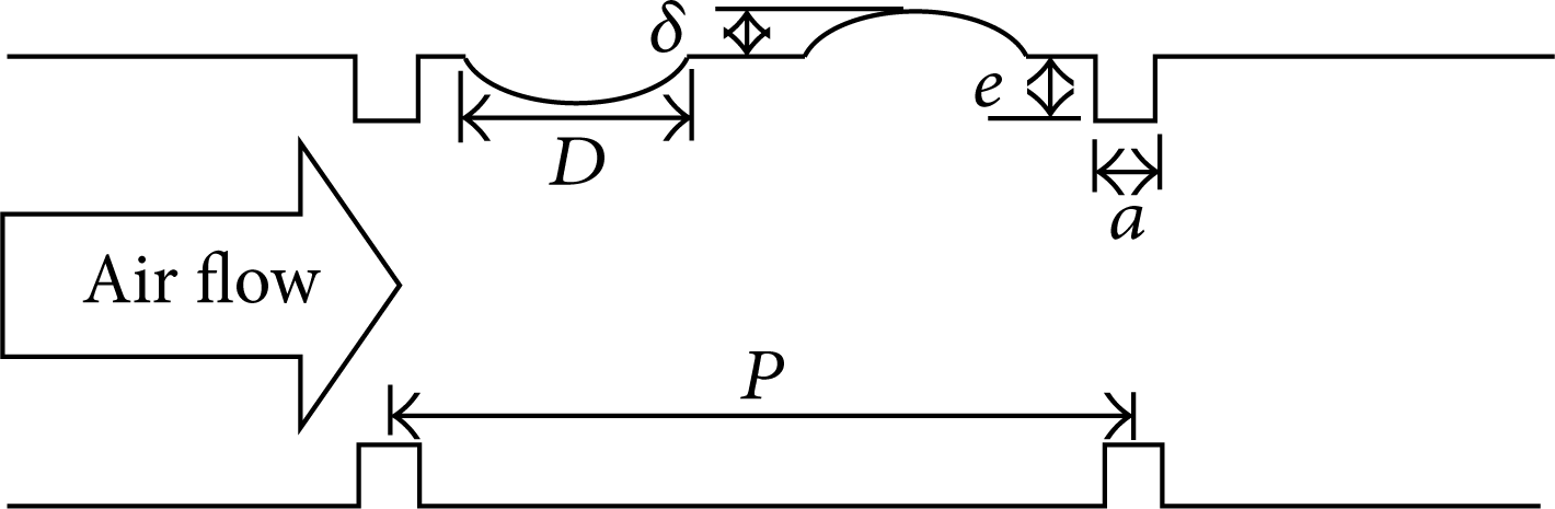
Cross-sectional view of the combination of ribs, dimples, and protrusions.
In this paper, there are four different configurations. In case 1, two rows of dimples are placed between two ribs, and the arrangement is shown in Figure 3. In case 2, instead of dimples, two rows of protrusions are placed between two ribs; the arrangement is the same as that of case 2. In case 3, along the flow direction, one row of dimples and one row of protrusions are placed between two ribs; the arrangement is the same as case 1 and case 2. In case 4, on the contrary, along the flow direction, one row of protrusions and one row of dimples are placed between two ribs. The detailed parameters are presented in Table 1. All cases are researched under Re = 10000, 50000, and 100000.
Parameters of the cases.

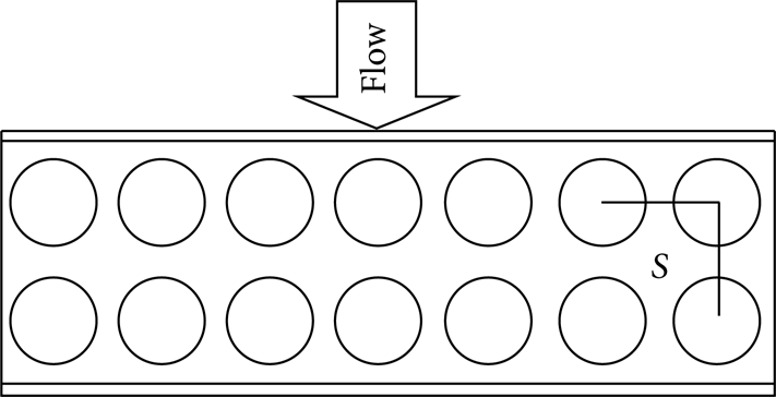
Top view of the dimple/protrusion arrangement.
2.2. Computational Method and Boundary Condition
The Navier-Stokes equation in its steady form is solved using the finite-volume based computational fluid dynamics solver FLUENT. The SIMPLEC algorithm is used to solve the pressure-velocity coupling. The standard scheme is used for pressure discretization. In this paper, Reynolds number ranges from 10000 to 100000, and the corresponding velocity ranges from 3.135 m/s to 31.35 m/s. The flow in the channel can be considered as incompressible flow. Besides the default quantities (such as continuity, energy, and velocities), the pressure gradient per unit length of the channel and the area-averaged wall temperature are considered to judge the convergence of the computations. The computations are considered to be converged when the residues for continuity, energy, velocities, and pressure gradient per unit length of the channel are less than 1 × 10⁻⁶, 1 × 10⁻⁷, 1 × 10⁻⁷, 1 × 10⁻⁴, and 1 × 10⁻⁴, respectively. Fully developed periodic velocity and temperature will be obtained after a certain number of obstacles in streamwise direction. In this case, a periodic geometry can be chosen to minimize the computational cost. In the ribbed rectangular channel, fully developed periodic velocity and temperature will obtained after x/D h >3 as Han [7] reported. The smallest periodic domain is shown in Figure 4. Turbulence model chosen in this paper is realizable k-ε model as Lan et al. [20] used; a clear comparison of different turbulence models has been shown in the paper. The boundary conditions are as follows: (a) a uniform heat flux of q = 1500 W/m2 is applied at the top and bottom surfaces of the channel. (b) No-slip boundary condition is applied at the four external surfaces of the channel. (c) Transitional periodic boundary condition is applied at the inlet and outlet.

The smallest periodic domain.
2.3. Grid Information and Data Processing
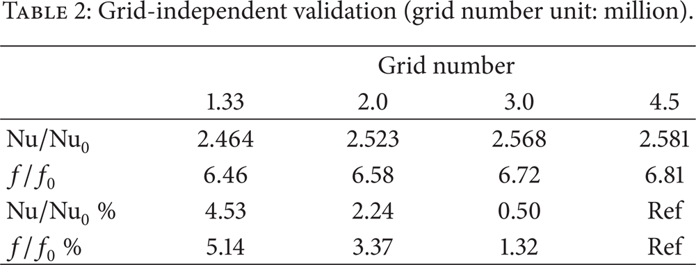
The computational grid consisted only of hexahedral grid. An O-grid was generated around the ribs, dimples, and protrusions and an H-type grid was generated for the flow core. The averaged Y+ value was less than 1.0 for all cases. Taking case 1 as example, Figure 5 shows an amplified view of the grid around the ribs and dimples. Considering the computational precision and time, the grid independence verification is needed. Taking case 1 at Re = 50000, for example, four types of grids are analyzed for the present study. The grids are systematically refined with a constant grid refinement ratio 1.5. Table 2 shows the grid independence verification. From Table 2, the Nu/Nu0 and f/f0 change by 0.5% and 1.32% from grid 3 to grid 4; hence the grid number about 3.0 million is chosen and is selected for other cases. It takes about 48 hours to complete one case with eight Q8200/2.33-GHz processors used.
Grid-independent validation (grid number unit: million).

Amplified view of the grid distribution near the dimples and rib corner.
In this paper, the Reynolds number is defined by

where Um,in is the inlet average velocity. The hydraulic diameter D h is given by

The local Nusselt number is described as

where λ is the thermal conductivity of air. The local heat transfer coefficient hx is defined as

where q″ is the heat flux. ΔT x is the local temperature difference between the wall and the air which can be obtained as follows:

where Tw·x and T x are the local wall and bulk mean temperatures, respectively.
The average Nusselt number for the channel can be calculated by
The Fanning friction factor f is defined as

where Δp is the pressure drop. L is the streamwise channel length of the computational domain.
The thermal performance [20] is defined as
The baseline Fanning friction factor f0 [20] is calculated by

The baseline Nusselt number Nu0 [20] is given as

3. Computational Results and Analysis
3.1. Heat Transfer Performance
Figure 6 presents the average Nusselt number of different cases at different Reynolds numbers. It can be observed from the figure that the combination of ribs, dimples, and protrusions has considerable effect on the heat transfer performance. The range of Nu/Nu0 is 1.892–2.774 in different cases. With the increase of Reynolds number, the Nu/Nu0 value is also increased. Comparing the value of Nu/Nu0 in all cases, we conclude that case 4 (rib + protrusion + dimple) presents the best heat transfer enhancement in the range of the Reynolds numbers. Case 1 ranks just behind case 4. Case 2 shows the lowest Nu/Nu0 value.

Nu/Nu0 variations with Reynolds number.
3.2. Friction Characteristics
Figure 7 presents the normalized friction factor of different cases at different Reynolds numbers. The main feature is that f/f0 increases as Re increases in each case. The range of f/f0 is 4.162–8.418 in different cases. Case 3 and case 4 show the same trend of f/f0 which varies with Reynolds number, and the f/f0 remains the same in all Reynolds numbers and is the highest among all cases. Case 2 shows the lowest f/f0 value.
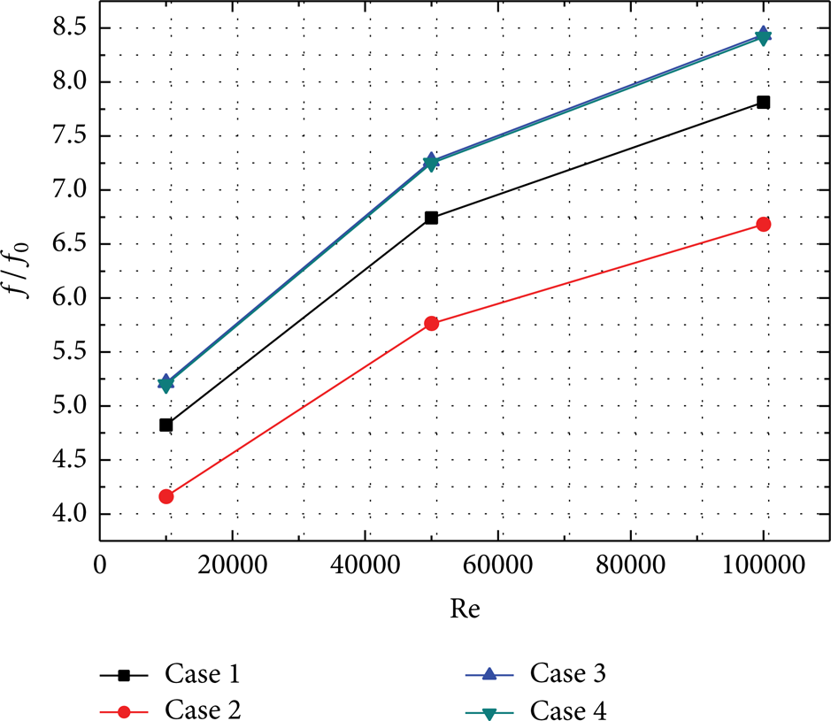
f/f0 variations with Reynolds number.
3.3. Thermal Performance
Figure 8 presents the thermal performance of different cases at different Reynolds numbers. TP in each case increases as Reynolds number increases. Case 1 and case 4 perform much better than case 2 and case 3, and The TP value of case 2 is nearly the same as case 3. TP value of the case 1 is higher than case 4 in all range of Reynolds numbers, and it is about 1.73% higher at Re = 100000.
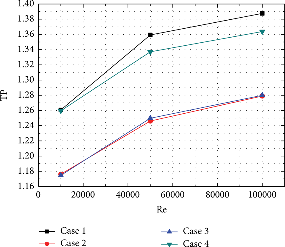
TP variations with Reynolds number.
3.4. Flow Characteristics and Local Nu Distribution
By an examination of all cases, the flow characteristics are nearly the same at different Re for each case. Taking Re = 50000 as example, Figure 9 shows the streamlines and temperature contours at the center plane (z = 0) near the ribbed/dimpled/protrusioned walls, and Figure 10 shows the local Nusselt number distribution of each case. Air flow direction of each case is left side to right side in Figures 9 and 10. It can be observed from the Figure that there exist flow separation and reattachment in each case. In case 1, as the mainstream flow near the wall passes over the rib, it separates from the wall due to the rib and a big recirculation occurs within the first row of dimples, and then the mainstream flow reattaches to the wall at the downstream edge of the first row of dimples, and there are no separation and recirculation in the second row of dimples, agreeing well with Figure 10; the local Nu number is high in the downstream edge of the first row of dimples. In case 2, the mainstream flow separates from the rib and reattaches at the windward side of the first row of protrusions and the recirculation is smaller compared with case 1, and there is a small recirculation between two row of protrusions and another reattachment occurs at the windward side of the second row of protrusions. In case 3, the mainstream flow reattaches to the downstream edge of the dimples and the windward side of the protrusions. A big recirculation occurs within the dimples and small recirculation occurs between the protrusions and next ribs. In case 5, the mainstream flow separates from the wall and reattaches at the windward side of the protrusions and at the downstream edge of the dimples. The first recirculation occurs between the first ribs and the protrusions, second recirculation occurs within the dimples, and another small recirculation occurs between the dimples and ribs.

Streamlines and temperature contours at the center plane (z = 0) near the ribbed/dimpled/protrusioned wall at Re = 50000.

Local Nusselt number distribution at Re = 50000.
Observing all cases in Figure 10, higher local Nu number values are located at the rib surfaces. In case 1, higher local Nu number values are located at the rib surfaces and near the downstream edge of the first row of dimples where the mainstream flow reattaches to, and relative low local Nu number is located in the upstream portion of the dimples where recirculation occurs. In case 2, higher local Nu number values are located at upstream portion of the first row of protrusions and relatively high local Nu number values at upstream portion of the second row of protrusions due to the fact that the mainstream flow reattaches to the wall and lower local Nu number values occur at the wall where small recirculation presents. For case 3, higher local Nu number values are located at the downstream edge of the first row of dimples and upstream portion of the second row of protrusions due to the fact that the mainstream flow reattaches to the wall and impinges on the protrusions. For case 4, considerable local Nu number values are located at the rib surfaces compared with other cases and also at upstream portion of the first row of protrusions.
Comparing Figures 9 and 10, when the mainstream flow reattaches to the wall, it can impact the wall and the cooling air can make the higher heat transfer in there, so higher local Nu number values are located at where mainstream flow reattaches to.
4. Further Study about the Influence of Protrusions in Case 4
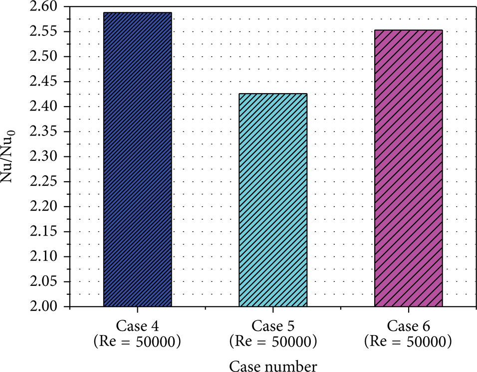
Based on the research of the four cases above, case 4 shows better performance in the heat transfer. However, big protrusions can make greater pressure drop than dimples. In this paper, further study has been done for the influence of protrusions in case 4 in order to find the optimal protrusion dimensions. In all cases, only different diameter of protrusion has been chosen, D = 15 mm (case 4), 10 mm (case 5), and 6 mm (case 6), respectively, and δ/D = 0.2 in all different cases; other conditions are the same in all cases. The Nu/Nu0, f/f0, and TP value are also obtained. By examination of all cases, the trend of the values is nearly the same at different Reynolds numbers. Taking Re = 50000, for example, Figure 11 shows the Nu/Nu0 in different cases, Figure 12 presents the f/f0 of different cases, and Figure 13 gives the TP value of different cases.
Nu/Nu0 in different cases at Re = 50000.
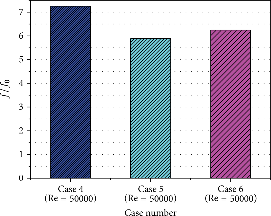
f/f0 in different cases at Re = 50000.

TP in different cases at Re = 50000.
It can be observed from Figure 11 that when the diameter of the protrusion deceases the Nu/Nu0 of the rib + protrusion + dimple also decreases, compared with case 4. For case 5 (D = 10 mm), it is about 6.3% smaller than case 4, and, for case 6 (D = 6 mm), it is about 1.35% smaller than case 4.
Figure 12 compares the friction characteristics of all the cases. For case 5, the value of f/f0 is about 18.75% lower than that of case 4. For case 6, the value of f/f0 is about 13.86% lower than that of case 4.
Figure 13 presents the thermal performance (TP) of all the cases. It can be noted that case 6 performs much better than other cases in thermal performance; it is about 3.7% higher than case 4. For case 5, it is about 0.4% higher than case 4. Compared to case 1, TP of case 6 is about 1.96% higher.
After the research of influence of protrusion diameter, it can be concluded that when the diameter of protrusion is 6 mm, the performance of rib + protrusion + dimple is the best.
5. Conclusion
Numerical simulations were conducted in this paper to investigate flow characteristics and heat transfer performances in a rectangular channel with the combination of ribs, dimples, and protrusions. And optimal structure also has been discussed in this paper. The considered Reynolds number range is 10000–100000. The results indicate that the combination of ribs, dimples, and protrusions in a rectangular channel is effective for heat transfer enhancement. The following conclusions can be drawn from the present work in detail.
The Nu/Nu0, f/f0, and TP value increase as Re increases in each case. For the same Reynolds number, the rib + protrusion + dimple case is the highest Nu/Nu0 value and rib + protrusion is the lowest.
The rib + dimple + protrusion case and rib + protrusion + dimple case show the same friction characteristics, and the f/f0 value is the highest of all cases for the same Reynolds number.
The rib + protrusion case provides the lowest value in both Nu/Nu0 and f/f0. As a result, the thermal performance of the rib + protrusion case is nearly the same as the rib + dimple + protrusion.
Among all cases, the rib + dimple case provides the most considerable thermal performance.
Under study of structural improvement about diameter of protrusion in case 4, when the diameter of protrusion is 6 mm (Case 6), it is much better for the case of rib + protrusion + dimple in thermal performance, it is about 3.7% higher than case 4 and is about 1.96% higher than case 1, and the friction characteristics are also better than case 1 (rib + dimple).
Case 6 is the best choice of compound heat transfer enhancement structures.
Footnotes
Nomenclature
Conflict of Interests
The authors declare that there is no conflict of interests regarding the publication of this paper.