
Abstract
The presented paper deals with the design of a mathematical model of a rejection filter for the drives stabilization applied to pressure die casting processes. The rejection filter allows the stabilization of electrohydraulic servo drives making use of periodically repeated zero transfer functions while taking advantage of the essence of a parallel joint of the proportional unit and a time delay unit. Consequently, the model of the adaptive rejection filter algorithm with a higher form of electrohydraulic servo drives has been mathematically elaborated. The paper comprises the algorithm description for the models implementation in the process of a servo drive control, which to a sufficiently greater extent can respond to the changes in technological parameters of pressure die casting than a conventional drive system. The introduction of a position feedback or a high-speed feedback allows the elimination of excessive porosity formation. By Introducing additional feedbacks, it is possible to affect the speed of a piston movement in the range of a low pressing speed depending on other technological parameters, for example, a melt temperature in the chamber.
1. Introduction
The piston movement rate within the filling and injection phases is directly related to the porosity occurrence as well as the morphology of gas impurities [1–3]. The design of drive systems and their control structures is an important stage in terms of the concept of pressure die casting machines.
At present, hydraulic drives are almost exclusively used to move piston [4, 5]. Among their basic attributes there are high motion resetting forces, low inertia, simplicity, reliability, and linear motion excluding a gearbox application [6]. On the other hand, there are several disadvantages of using such systems. The basic disadvantage compared to the use of electric drives is the requirement of a hydraulic pressure economy, the existence of a hydraulic system leakage, a flexibility of linear hydraulic drives, and the existence of a bleeder resistor [3, 7].
The most common types of endogenous bubbles when casting under pressure are gas impurities and shrinkages. One of their causes is an improper speed of a die-cast cylinder [1, 8–10]. This is the cause of an excessive mixing of air in the melt [3, 7, 11, 12]. During the cylinder movement, the speed changes according to its position. At the same time, the level of the molten metal in front of the piston gradually increases. At the beginning, the cylinder moves slowly. Before the level reaches its maximum, the cylinder accelerates rapidly. The last phase of the cylinder movement takes place at a high speed, thereby filling the mold [5, 13].
As the piston moves forward, a wave is created in front of it, which may encounter a reflected wave. In the middle of the chamber, the crest of the wave occurs and air turbulence as well as air entrapment appears (Figure 1). The best solution is to move the piston only after the wave is reflected from the piston; it means that the piston moves in the same direction as the original wave, thus minimizing the amount of the entrapped air. Another way of reducing a potential formation of bubbles is to design such a shape that the chamber is filled up to 50%. A critical point is the acceleration of the piston movement from the resting state to the desired speed. If the acceleration is too large, the so-called foamed wave supporting bubbles formation is created in front of the piston (Figure 1). If the acceleration is slow, the wave approaches the mold; it is reflected and returns to the moving piston. Here, a risk of creating a large bubble occurs [3, 7, 11, 12].
Penetration of air bubbles due to the movement of a die-cast cylinder [14].
2. Analysis of the Applied Methods to the Electrohydraulic Servo Drives Stabilization
Based on the analysis of the presented problem, a servo drive and a control system for the application to pressure die casting have been designed. The servo drive control system can substantially better respond to the changes relating to the technological parameters requirements in the process of casting under pressure than a conventional drive system [4, 5, 15–19]. The introduction of a position feedback enables to eliminate the excessive formation of porosity [5, 20–23]. The application of additional feedbacks such as high-speed feedback allows to control the speed of the piston movement in a low pressing speed range movement in a low pressing speed range depending on other technological parameters such as the melt temperature in the chamber. By installing pressure sensors, by means of a position feedback, it is possible to control the static pressure in a casting mold. These are the main reasons why in the following section of the paper we will deal with the analysis of electrohydraulic servo systems considering their application to a pressure die casting technology and their essential parts as well as their control system.
A servomechanism is characterized as a control loop to regulate the position or any of its derivatives. Electrohydraulic servomechanism comprises a servo valve to control the flow of a pressure oil, the actual hydraulic drive, and the sensing devices for the controlled variable sensing (Figure 2). When formulating a transfer function of the drive system with respect to the objectives of this work, we will deal exclusively with electrohydraulic servo drives with linear cylinders.

Scheme of an electrohydraulic servo drive [24].
A block diagram in Figure 3 shows the basic concept of the electrohydraulic servomechanism in a position feedback. It is a linearized model. In terms of a particular application, a servo valve and a linear hydraulic motor are the most important elements of a loop. Concerning high-speed servo drives, amplifiers, and position sensors, eventually speed sensors are designed in order to affect the dynamic properties of the control loop to a minimum extent.

Block diagram of an electrohydraulic servo drive [25].
A servo valve operates as a controllable energy source. It is the most demanding part of the entire servomechanism concerning its manufacturing. The control variable of a servo valve is the input current. The output variable is the flow rate through the slide edges. Currently, a two-stage servo valve concept prevails. The first stage is an electrohydraulic amplifier, and the second stage comprises a servo valve slide. The slide position is equipped with electric and eventually mechanical feedback [6, 24].
Via the analysis of the methods used so far for the stabilization of electrohydraulic servo drives, it can be concluded that the use of corrective and stabilizing elements leads to the deterioration in some dynamic properties of control loops. In particular, it refers to the deterioration in the quality of a regulation process and time responses. Due to a low damping, overregulation occurs, and eventually a significantly excessive resonance frequency makes it difficult to achieve the desired amplitude safety. If in the loop there is also astatism, the situation becomes complicated due to the exhaustion of a phase safety by that element. Regarding the stabilization of hydraulic servo drives, it is necessary to keep in mind that the excessive resonance is in a low frequency range [20, 22, 26–28]. Therefore, it is rather difficult to design such an element that in an effective manner would create a sufficiently stabilizing effect.
These facts are the basis for the design of the rejection filter. The essence of the filter consists in the rejection creation as a counterpart of an excessive resonance. In the case of the designed filter, the rejection is infinite and an excessive resonance is eliminated sufficiently. As the existence of the rejection is limited in terms of a bandwidth, it has a minimal effect on the dynamic properties of the control loop. The filter has been designed as a parallel joint of a time delay element and a proportional element. It is then apparent that there is an intentional involvement of a time delay in the control loop. This may result in the damping of a step response.
3. Model of the Rejection Filter
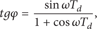
A rejection filter is characterized by a periodically repeated zero transfer function of the amplitude or by periodic rejections. The essence of the rejection filter consists in a parallel joint of a proportional unit and the unit with a time delay. Its basic transfer function can be characterized by the relation
The filter frequency response in a complex plane is shown in Figure 4. When passing through the origin of the coordinate system, the transfer function of the amplitude is equal to zero. With the implementation of the so-called artificial time delay, in principle, it is possible to proceed in two ways using the Padé approximation by digital loops or by creating reservoirs, among which the input signal is transferred due to which a time delay occurs.

Frequency response of the rejection filter.
3.1. The Rejection Filter Transfer Function
In order to derive the filter transfer function, let us assume that the signal input to the filter has a harmonic course [29]. Let us consider the Z transfer function of the input harmonic signal in the following form:

The signal in the branch with the time delay v is in the form of a phase-shifted harmonic signal as follows:
The output signal is in the following form:

The resulting transfer function of the digital rejection filter is analogous to its continuous form as follows:

In order to derive the transfer function of the amplitude and the phase, the substitution is introduced as follows:

And we will introduce the Z transfer function sin(ωT + φ) as follows:

Comparing the previous relations, we obtain the following equation:

whereas K formally represents the transfer function of the amplitude. Substituting for z = e jωT and z−n = e−jωTd, we will find out the transfer function of the phase of the amplitude K. Comparing the real and imaginary components of the left and right side of the modified equation, the following relations are obtained based on the comparison of the real part as follows:

which after the modification will give the relation
and an imaginary part

or after the multiplication

After substituting K for (10), we obtain the phase transfer function as follows:
whereas, after the modification, the amplitude transfer function is obtained as follows:
For further solution procedure, it is advantageous to introduce the concept of a continuous-time rejection filter. Such filter differs from a real one in a fictitious replacing of a discrete signal transfer in the branch with a time delay by a continuous-time signal. Unlike the physically realizable filter, the continuous-time filter is a mathematical fiction, which is particularly useful in assessing its properties while really characterizing the filter in the sampling time instants [26–29]. In order to derive the transfer of the continuous-time rejection filter, it is again necessary to keep to the substance of a parallel joint of a proportional element and an element with a time delay. The filter output signal is given by the relation

where T d is the time delay magnitude, eventually in the operator's form

So the continuous-time filter transfer function is

Based on Euler's relations, it is also possible to derive the amplitude and phase transfer functions using this relation. These relations are completely identical to the relations that were derived for the real filter.
4. Synthesis of Electrohydraulic Servo Drives and a Rejection Filter
We assume the continuous-time transfer of the filter (1). The filter frequency response in the complex plane is shown in Figure 4. Its response indicates cyclically repeated amplitude responses. The essence of the filter application is that the frequency response at the frequencies

where K f is the filter gain in the range (0. 1). This leads to the attenuation of the time delay effect in the filter. In other words, the rejection magnitude changes to finite magnitude.
The peak amplitudes, that is, when

The basic condition for the successful use of the filter in control loops with electrohydraulic servo drives is for the rejection frequency to respond the resonance frequency. The most effective filter effect is achieved if the first rejection eliminates an excessive resonance. Based on that, it is possible to derive the relationship between the rejection and resonance frequencies and eventually between the time constant of the drive and a time delay. For the resonance frequency, the following applies:

where ω m is the drive frequency. This frequency has to correspond with the first rejection frequency of the filter (i.e., k = 0); therefore it holds

For

of which, after the modification, a relation between the time constant of the system and the magnitude of the filter time delay follows

The filter is implemented as a CCD element and as a special utilitarian controller which realizes the A/D conversion of the input signal, its processing in terms of Algorithm (5), and a D/A conversion. The controlled variable is the actual position of the hydraulic cylinder y(t), and in physical terms it refers to voltage from the position sensor. The filter is a parallel connection of the unit member and the member with the time delay. The value of the time delay corresponds to the time constant of the controlled electrohydraulic actuator or in general the time constant of the controlled system. The time delay is realized on the basis of CCD elements connected in series. The number of CCD elements is determined by the size of the required time delay. The shift of the input signal towards the output was time synchronized by a sampling rate of the A/D converter. At the output of the filter there is a D/A converter, which generates a continuous control signal in the form of voltage. This signal is transformed to the control current signal that is a manipulated variable of the control servo valve.
4.1. Design of the Adaptive Rejection Filter
The algorithm of the adaptive rejection filter is a higher form of the electrohydraulic servo drives stabilization. The adaptive filter has been designed to respond to the changes of the systems dynamic properties, which arise due to the changes in operating regimes as well as to the changes in physical properties.
The adaptive filter is designed based on a recurrent algorithm that is considered a discrete one. If the sampling frequency is many times higher than the natural frequency of the controlled actuator, it is possible to work with a filter continuous interpretation according to a transfer function (1) provided that the continuous filter is a mathematical interpretation, which coincides with the discrete version of the filter at the sampling moments.
The design of the adaptive rejection filter is primarily based on the selection of an appropriate identification method. The design of the adaptive algorithm is based on the requirement for a real-time processing. This is why the identification is demanding and a number of computational steps are limited [20, 22, 26]. Therefore, further on, we will rely primarily on continuous methods of adaptive identification. The adaptive filter algorithm solves three tasks. The first task is to measure the inputs and outputs of the system; the second one is the identification process and parameters determination of a discrete mathematical model. The third task is the determination of the filter parameters and their operational intervention.
The algorithm design is based on the knowledge that the change to the resonance response can be accurately identified on the basis of the changes in the system properties. When identifying the servo drive parameters, considering the filter application, the damping ratio magnitude is not crucial but the time constant, and eventually the natural frequencies are decisive. Based on these identified parameters, it is possible to determine unambiguously the drive resonance response.
A controlled variable is the actual position of the hydraulic cylinder y(t); in physical terms it refers to voltage from the position sensor (see Figure 3). This signal is delayed and shifted in time by the value of the time delay T d , which corresponds to the time constant (according to (23)) of the controlled electrohydraulic actuator or of the generally controlled system. A time delay is realized on the basis of CCD elements connected in series. The manipulated variable u(t) is the control current to the actuator.
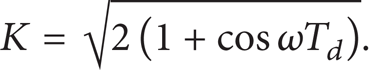
The application of this method satisfies the requirements for a fast processing of information. Let us suppose that, up to the kth time instant, the

where

To start calculating the adaptive identification, it is required to enter the initial values of the parameters vector
The overwhelming majority of processes are stochastic in nature. It follows that the measured output is not clearly determined only by the input values and its past, but random effects, whose source is unknown and eventually even cannot be determined, are also manifested here. Let us start with the description of the system in the form of the so-called static linear regression model as follows [30]:
where K0 is the constant, e(t) is a random component with a zero mean value, Q
i
, P
i
are the coefficients of output and eventually input signals, and
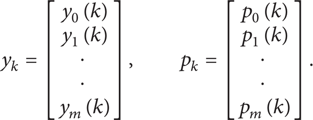
Further on, it is assumed that e(t) is uncorrelated with inputs, outputs, and other values. After providing a formal discretization, for the kth time instant, we can write

where A
i
, B
i
are the coefficients of discrete outputs and eventually inputs. If we introduce the parameter vector

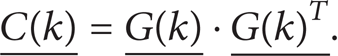
Like most practical applications, the Refil filter is also based on the least squares method. Information on minimum inputs and outputs forms a system in the matrix
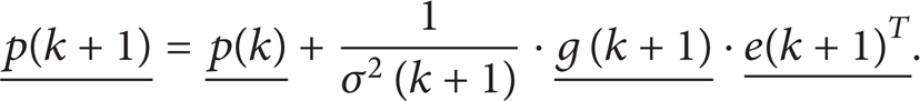
From the numerical point of view, it is advantageous to update the factors of the matrix

The design of the algorithm of the adaptive rejection filter is shown in Figure 5. It ensures the measurement of input and output variables in the identified system, parameters estimate based on the information obtained, the calculation of the resonance frequency, and the determination of the filter parameters.
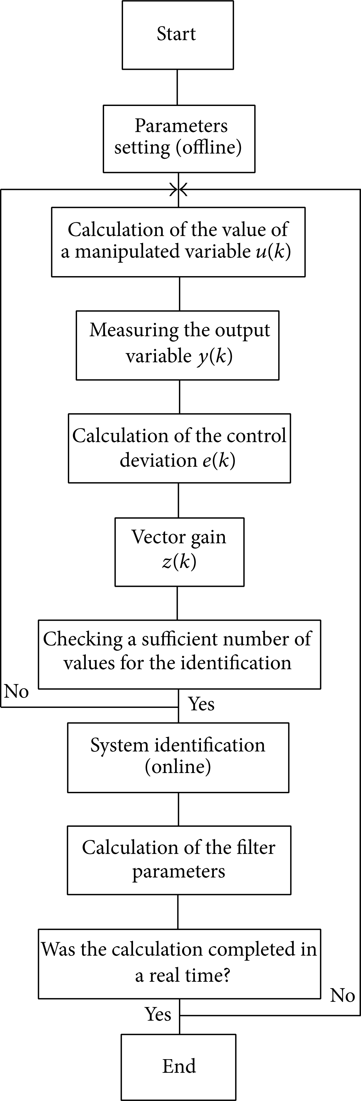
Adaptive filter algorithm.
The adaptive filter makes use of the possibilities offered by a digital control and processing of the control algorithm in real time. As a model, the servo drive with the transfer function was used as follows:
Eventually

whereas the input variable is the control signal u(t) and the output variable is the signal y(t). The Z transfer function is obtained from the transfer function (34) via a classical procedure. The step response has the form

If
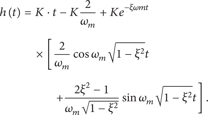
then, using the Z transformation, the following Z transfer function corresponds to a continuous-time transfer function (34):

Modifying (37) to a common fraction, the transfer function can be written in the form

whereas the individual elements A i , B i are determined by the following relations:
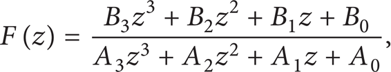
Based on the transfer function (37), a differential equation can be derived on the basis of which parameters estimate will be determined as follows:
Eventually, as A3 = 1,

This differential equation is the basis for the parameters p(k) estimate. The data matrix in this case is in the form


Based on each new parameters estimate, the relations (41)–(43) are used to determine the current value of the natural frequency ω m , the damping ratio ξ m , and the gain K. In our case, we are interested in obtaining only the value of the natural frequency and based on it in determining its value according to the relation for a resonance frequency (20). According to (23), which is the condition of the consistency of the resonance frequency with the rejection frequency, it is necessary to carry out the change of the filter parameters and perform an operational intervention. This is the essence of the adaptive algorithm of the rejection filter. As proved by the experience, in order to estimate the damping and the natural frequency, it is advantageous to use the coefficients A i because for the range of the operating natural frequencies 10–50 Hz they gain higher values than the coefficients B i . As a result, the coefficients A i converge substantially faster.
The identification method utilising the Refil filter provides the parameters estimation in steps. This means that the parameters satisfactory estimation needs to be carried out in the course of time that is available and is limited by the validity of Shannon's theorem. This is particularly in the case of the differential equation (40) rather difficult in terms of time, especially in such a case if the input signal is stabilized. Via the simulation, it was found out that the results of the parameters estimate by the Refil filter are satisfactory for electrohydraulic servo drives whose frequencies are higher than 20 Hz. For lower frequencies, the parameters values A i are small which does not allow the estimation of the equation parameters with a sufficient accuracy. For these systems, it would be suitable to apply the method of a shadow identification, where the convergence is significantly faster than it is by the Refil method. The scheme of the control loop of electrohydraulic servo drive with adaptive rejection filer is on Figure 6.

Block diagram of implemented adaptive rejection filter.
5. Results and Discussion
The essence of the filter application in control loops with electrohydraulic servo drives lies in eliminating excessive resonance of the hydraulic motor by the filter rejection. The problem of electrohydraulic actuators stabilization in a position feedback lies primarily in the fact that the amplitude frequency logarithmic response is characterized by a relatively high resonant frequency excess with the phase shift asymptotically approaching φ = −π. A phase safety of the control loop is in addition in the whole frequency band exhausted by a phase shift φ = −π/2. Therefore, the use of a filter is an effective tool for regulation. The natural frequency of the actuator is very low, about 25 to 40 Hz. The width of the rejection band v is presented in logarithmic coordinates of the amplitude response. In case of any inconsistency between a rejection rate and a (resonant) frequency of the actuator, the application (according to (23)) of the filter is ineffective.
Figure 7 shows the amplitude response of the filter and the hydraulic servo drive. An amplitude drop does not occur up to the rejection frequency. The rejection frequency sufficiently eliminates the excessive resonance and the following peak amplitude is suppressed by a decrease of the amplitude response of the system with a slope of −40 dB/decade.
Filter frequency response with the electrohydraulic servo drive in logarithmic coordinates.
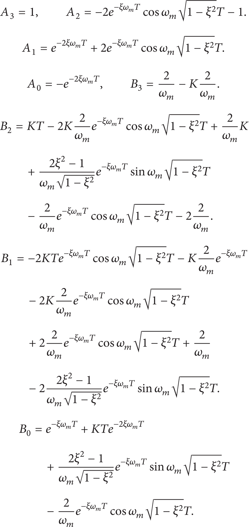
If in addition there is astatism in the circuit, as in the case of a position feedback of electrohydraulic servo drives, then the amplitude response is shown in Figure 8.

Frequency response of the electrohydraulic servo drive and the rejection filter with a position feedback.
In such a case, sufficient conditions to achieve the required amplitude safety will be established. As noted, the cylinder movement in pressure die casting involves a position feedback. This implies the natural astatism in the loop, so the mentioned amplitude transfer function is consistent with the amplitude transfer function of the electrohydraulic servo drive. The existence of astatism has another beneficial effect. The filter is the proportional element in the control loop, thus having a permanent regulation deviation. The integrator involvement, however, eliminates it.
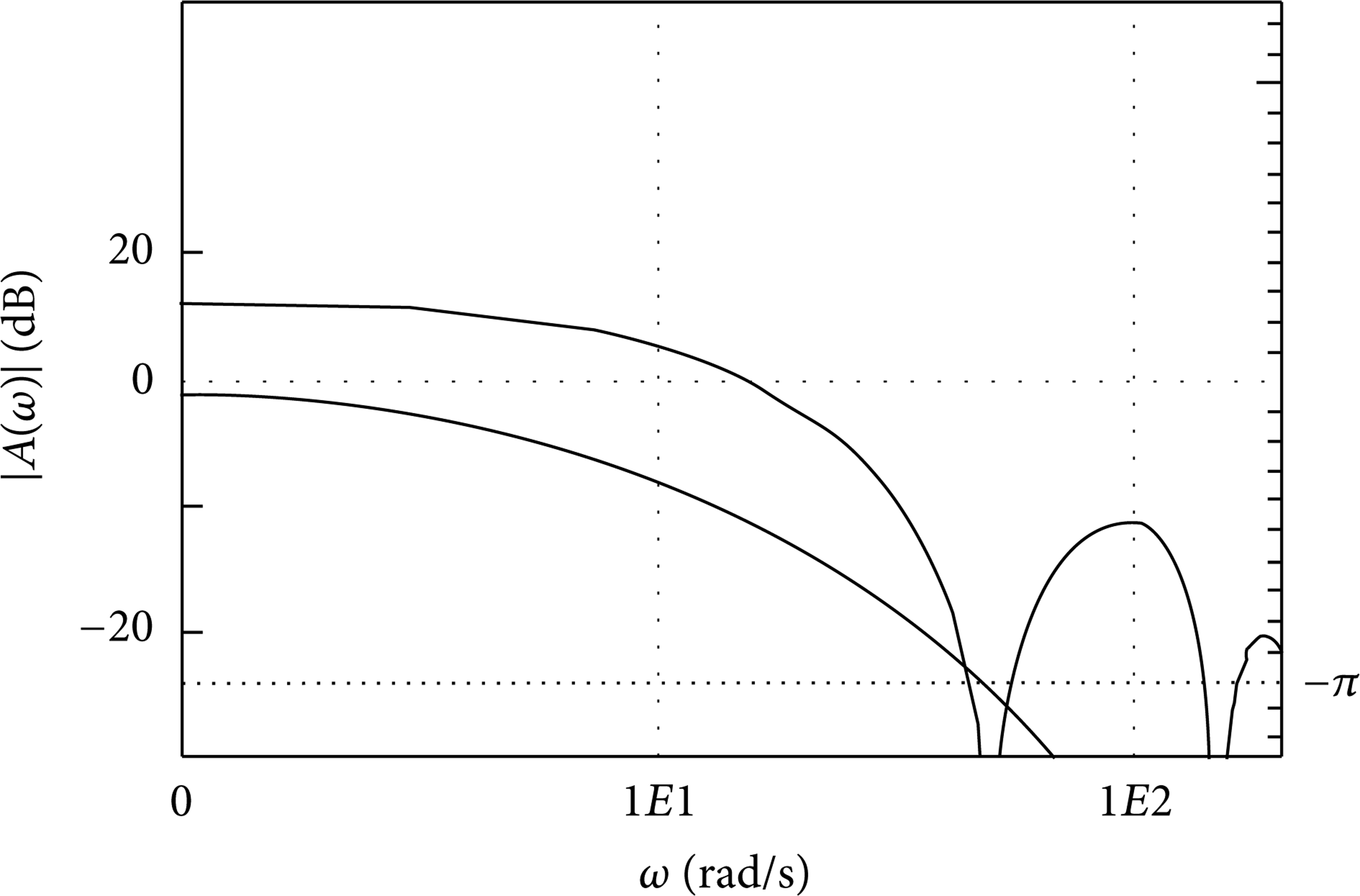
Within the time area, owing to the conducted experiments, a significant damping of electrohydraulic drives occurs. Figure 9 shows a step response of the hydraulic cylinder with the filter with a position feedback. Based on this figure, good stabilizing effects of the filter may be assumed.

Filter step response of the electrohydraulic servo drive with the filter and without the filter.
The stabilizing effect of the filter is so distinct that it is even possible to consider its utilisation with the drives with a minimum damping value (Figure 10).
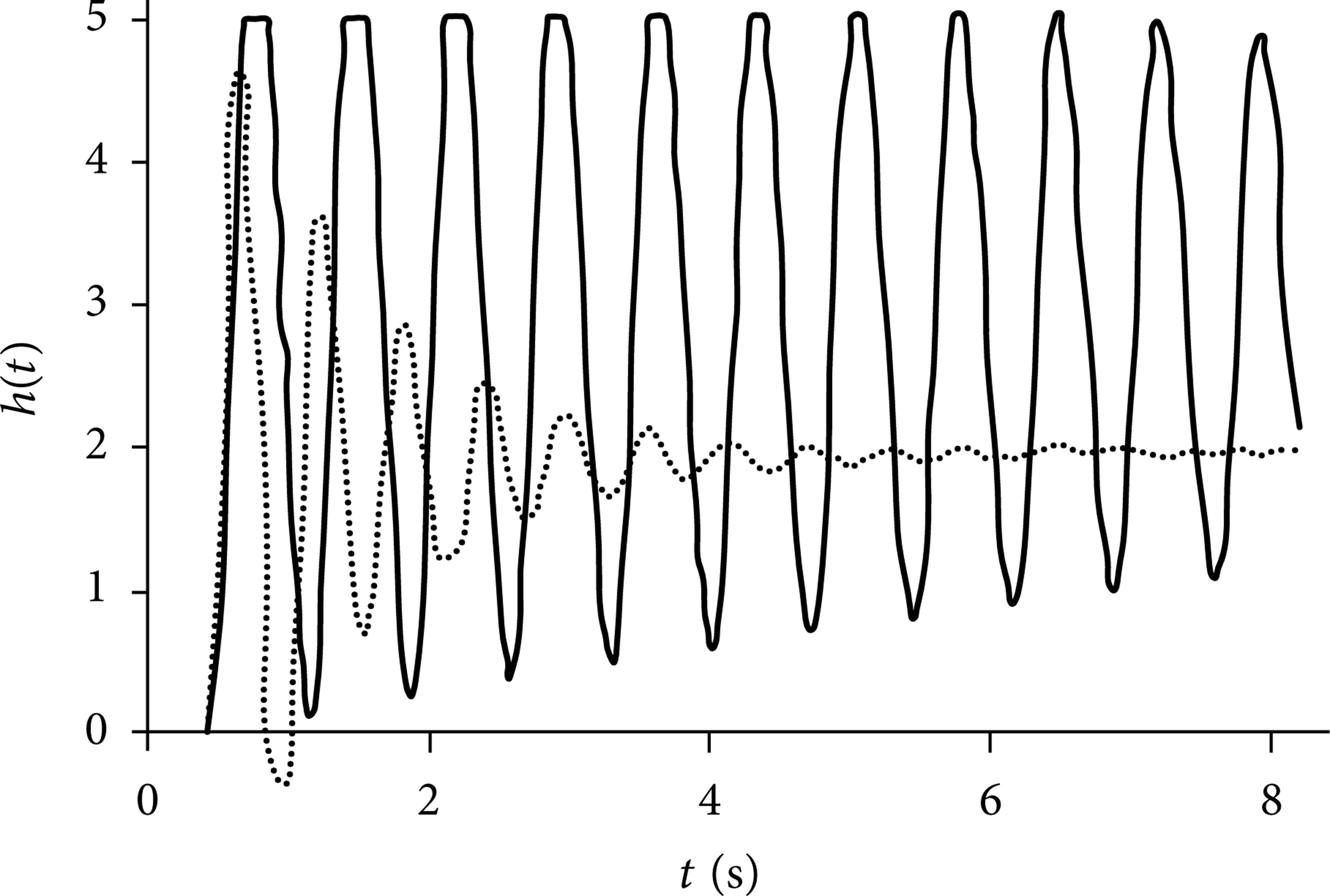
Drive stabilization with ultralow damping ratio.
6. Conclusion
Based on above mentioned results, it can be concluded that the use of the filter in the control loops with electrohydraulic servo drives can with a significant reserve stabilize the plunger movement inside the filling chamber of the pressure die casting machine. This stabilization allows the determination of the sequence of movements of the pressing plunger during the filling as well as the injection phase. In addition, the filter adaptive version will ensure that any deviations of the natural frequency of the servo drive are reflected in the filter responses. In case when the sampling frequency is much higher than the natural frequency of the regulated actuator, it is possible to work with a continuous interpretation of the filter which is identical with a discrete version of the filter at the sampling moments. As stated in the paper, a potential problem of electrohydraulic servo actuators stabilization lies mainly in the fact that the logarithmic amplitude frequency response is characterized by a relatively high resonance excess with a phase shift asymptotically approaching φ = −π. As it follows from the results, the rejection frequency of the desired extent eliminates a resonance excess and the following amplitude peak is suppressed by a decline in amplitude response of the system. Owing to the fact that in the loop there is a natural astatism that is generated by a positional feedback of electrohydraulic servo actuators, sufficient conditions for achieving the required amplitude security are created.
Based on this it can be concluded that the use of the filter is a suitable tool for the regulation of the pressing plunger position during the filling and metal injection process with pressure die casting machines.
From a broader aspect, however, it should be noted that many of the current concepts of the control of pressure die casting processes fall behind the potential of the existing control systems. In addition to introducing the position feedback, it is also possible to consider a pressure control as a subordinate feedback and a high-speed feedback. As it follows from the presented mathematical model, the application of the acceleration feedback will help not only to control the acceleration of the die-cast cylinder in order to avoid the occurrence of the wave inside the die-cast cylinder but also to increase the damping ratio of the hydraulic drive.
Conflict of Interests
The authors declare that there is no conflict of interests regarding the publication of this paper.
Footnotes
Acknowledgment
This work was financially supported by the Research of Real-Time Multiparametric Monitoring Methods of Manufacturing Machinery and Facilities Project (1/0975/11) of Scientific Grant Agency of the Ministry of Education of Slovak Republic and the Academy of Sciences (VEGA).