
Abstract
This study acquires the attitude dynamics of floating bodies with irregular configurations using an effective computational model, which has been validated theoretically and verified by experiments. By comparison a correlation formula was described to predict inclinations for the floating slender body imitating an excise torpedo. Thereafter a computational model was developed to account for bodies with attitudes in more general situations. For demonstration, a submersible was simulated to reveal that the inclinations vary abruptly around certain longitudinal locations of center of gravity. The property variations during water ingress assumption were presented. Similar to the virtue tank, an innovative concept of building the numerical data base for a specific floating body has been proposed, by which the position of its center of gravity can be obtained by interpolation from attitude data in tables as determined by the present computational model.
1. Introduction
There are some floating vehicles, such as ROV, UUV, submarine, and exercised torpedo, that dive according to their missions. The magnitudes and locations of weight and buoyancy in these marine vehicles are important factors in their motion or floating characteristics. By adjusting them, static and dynamic stability, in transverse or longitudinal direction, can be established [1]. In fact, some vehicles have been designed to be operational for certain particular requirements by virtue of the movement of their centers of gravity. In [2], the steady-state vertical ascent of a submarine with excess buoyancy was analyzed. In [3], the authors considered the attitude of the Mobile Target MK38 as the driving force to actively adjust the pendulum inside it for positioning its elevators and rudders to heave. In [4], a movable weight as an actuator to control the motion stability of underwater vehicles was used. Another case for taking advantage of the inclinations of a body is the Floating Instrument Platform (FLIP) [5]. This American research ship was designed to float not only like a conventional surface vessel with its keel horizontal but also with its keel vertical after suitable flooding. The attitudes of a floating cylinder with uniform material were investigated in [6], which showed that a cylinder having a length less than 0.707 of its diameter will float with its axis vertical, and when the length exceeds its diameter it will float with its axis horizontal. Obviously, the relations among weight, buoyancy, and their locations are strongly related to bodies’ states of equilibrium statically and dynamically [7, 8]. Nevertheless, the measurement of physical properties of a general body, for example, the floating attitude and center of gravity (CG), is not an easy task. A method and device for determining the CG by virtue of the test body floating in the tank was proposed in [9]. A system to obtain the CG of a body by basic statics and standard trigonometry was proposed by providing a balance arm and adding a disturbance weight [10]. Other than that, those devices were somewhat complicated and not suitable for heavy vehicles such as torpedoes and submarines [11, 12].
Stable floatation of some structures, such as offshore wind turbine [13] and floating skimmer et al. [14], are the key issue in practical use. The motivation of this study came from the deploying and retrieving problems of an exercise torpedo in sea trials [15]. When it floated after the first test run, it was oriented nearly 70 degrees vertically in the sea, which caused a lot of trouble in deploying and retrieving. Moreover, rapidly acquiring the CG during the weight and balance procedure before sea trials was a big concern because of the huge resources involved. In other words, a tool to predict the inclinations caused by weights and their locations is necessary in the design stage as well as during testing and evaluation for floating bodies. In recent decades, with more powerful computers and advanced software, the technique of computer-aided engineering (CAE) has enhanced the design process and has been applied to obtain the properties of maritime bodies of interest [16, 17]. Moreover, numerical simulation for real applications is cost-effective and accurate if the computational model has been validated [18]. To begin with our study, a practical correlation expression is first stated for inclinations of a floating slender body, which has been modeled mathematically by a cylinder [19]. Besides, a verified and validated computational model [20] is demonstrated to account for attitudes of bodies floating quasi-unsteadily, including a submarine-like submersible with ingress of water. Similar to the numerical offshore tank [17], the present numerical water tank is a development that takes into account the position of gravity acting on a floating vehicle from a numerical data base. Since fully nonlinear solution is not available, the empirical and analytical models are being considered and integrated to this proposed numerical simulator.
2. Modelling
2.1. Correlation for Slender Bodies
The general slender body configuration depicted in Figure 1 represents a floating torpedo. If W indicates the body's weight, B is buoyancy as the body submerged totally. Due to the body's slenderness, it can be assumed that the laterally biased CG is negligible in this problem of interest. Thus by manipulating equations for moment balance by assuming the center of buoyance as pole, we introduce the inclination factor K obtaining the following expression:
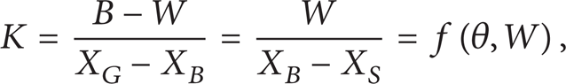
where X G , X B , and X S are the distance from the reference point to the CG, the distance to the center of buoyancy (CB), and the distance to centroid of the body's portion above water plane, respectively. Equation (1) indicates that the behavior of K depends on the magnitude, W, as well as the location of CG, X G , which is straightforward because B and X B are fixed values for a given body's configuration. Computationally, by keeping the body of interest floating in the water plane at a given inclination angle, θ, one can obtain the relations of B-W versus X G -X B by varying the magnitudes of weight and locations of CG. Figure 2 shows the calculated lines of B-W against X G -X B as determined by the available CAD software. This case is valid for a slender body with configuration similar to a torpedo or a submarine. Equation (1) can be rewritten as

where f is the corresponding correlation function. Meanwhile, it is clear that K is approximately invariant for a given inclination angle, as shown in Figure 2 for a specific slender body. Thus, a correlation can be deduced by the curve-fitting technique as

where K is expressed in dimension of kg/m and inclination angles θ are not greater than 30 degrees for the present specific case. Moreover, Table 1 presents the typical values of K for each angle θ with other physical characteristics for the slender body. The above expression was successfully used to predict the inclination angles of an exercise torpedo floating in several sea trials. However, this correlation expression is only valid for slender bodies, in which the biased CG is negligible laterally.
Typical values K with other physical characteristics of the slender body.

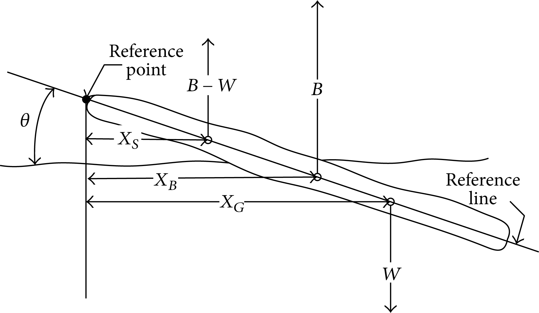
General sketch for a floating slender body.

Attitude relations of a floating slender body.
2.2. Benchmark for a Floating Cylinder
Before going further to simulate the attitudes of a floating body with irregular configuration, the benchmark of a floating cylinder is stated. Figure 3 shows the sketch of a floating cylinder at rest in a liquid, with diameter D, length L, and other notations. Based on the calculus and hydrostatics, the governing theoretical formula takes the following form [21]:

where Θ = cotθ,

Physical model of the floating cylinder.
The connection between (2) and (4) can be proved. We consider the case of a cylinder without biased CG; that is, η W is set to be zero. Equation (4) is solved and one can obtain θ = π/2 or

where the term inside the square root should be nonnegative. Equation (5) reveals the extreme case of the cylinder with its CG just slightly biased from the centerline laterally. It is not surprising that (5) is similar to (2). And the results have been validated by comparing with the sea trials of an exercised torpedo. Even though the CG of the torpedo was biased in this practical case, it was feasible to assume all forces acting on a straight line in our study. In other words, the inclination of the body floating on the sea is certainly caused by the biased positions of CG, whereas the position of CG in the longitudinal direction plays a key role.
However, it revealed that it is difficult to accurately measure the location of the CG of a body, especially in a radial direction. To remedy it, the present computational model has been employed to obtain the attitudes of bodies with irregular configurations.
3. Numerical Simulations
3.1. The Computational Model for Bodies with Irregular Configurations
For bodies other than regular configurations such as cylinders, a robust algorithm (BDM, body decomposition method) has been developed to simulate their attitudes [20]. By BDM, an arbitrary body is defined to be composed of objects with regular configurations such as spheres, cylinders, cuboids, cones, and disks, which can be easily constructed numerically as fundamental elements.
The simulation steps of the BDM are stated below and Figure 4 illustrates the relevant notations.
The XYZ coordinates, with the origin at upper surface corner, are fixed in the virtual computational domain.
The body coordinates ξ, η, γ are fixed in a body of interest; this coordinates can be transformed to XYZ without difficulty.
Define N objects O
n
of the body,
Determine the computational domain by a rectangular parallelepiped, with length
The location of CG in X direction is expressed as
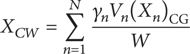
and similarly for Y, Z directions.
Divide the domain into small elements, layer by layer in the X-Z plane inside
Flood the body from below along Y axis, from layer 1 to j with maximum J to simulate the liquid surface in the X-Z plane.
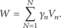
As calculation proceeds, sum the elements under the liquid surface and calculate the relevant buoyant force as

The location of CB in the X direction is expressed as
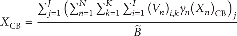
and similarly for Y, Z directions.
Stop flooding the body when the calculated buoyant force is equal to its weight; that is,
Judge if the net moment about Z axis,
If not, rotate the body about X axis and/or Z axis incrementally by small angles and recheck

Notations for an element layer in computational domain.
As stated above, the computational model is applied to acquire the attitude dynamics of floating bodies; however, this is reasonable only if transient process is infinitesimal to avoid added mass effect, damping, and drag forces induced from body's movement. In fact, the transient movement is not being modelled by the present system of equations without unsteady terms involved. Comparisons of other cases to show the robustness and accuracy of the present computational model are illustrated in Figure 5. Figure 5 shows the attitude dynamics from theory and present simulated results with parameters, L/D = 8, ξ W ′ = 4.6, and η w ′ = −0.065, of the floating cylinder for various dimensionless weights. The suitable mesh system has been employed in calculations with proper interpolations. Also note that the compared results of theory and present computational model are satisfactory except for ω less than about 6.8. Clearly, the simulations can be extended to cases of small ω values, which represent cases of the cylinder floating nearly horizontally.
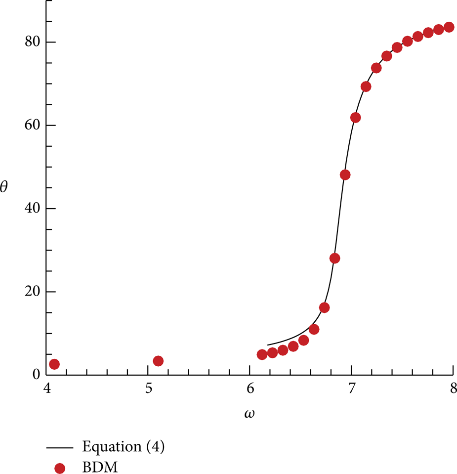
Comparison of numerical and theoretical results.
3.2. Submersible That Has Taken on Water
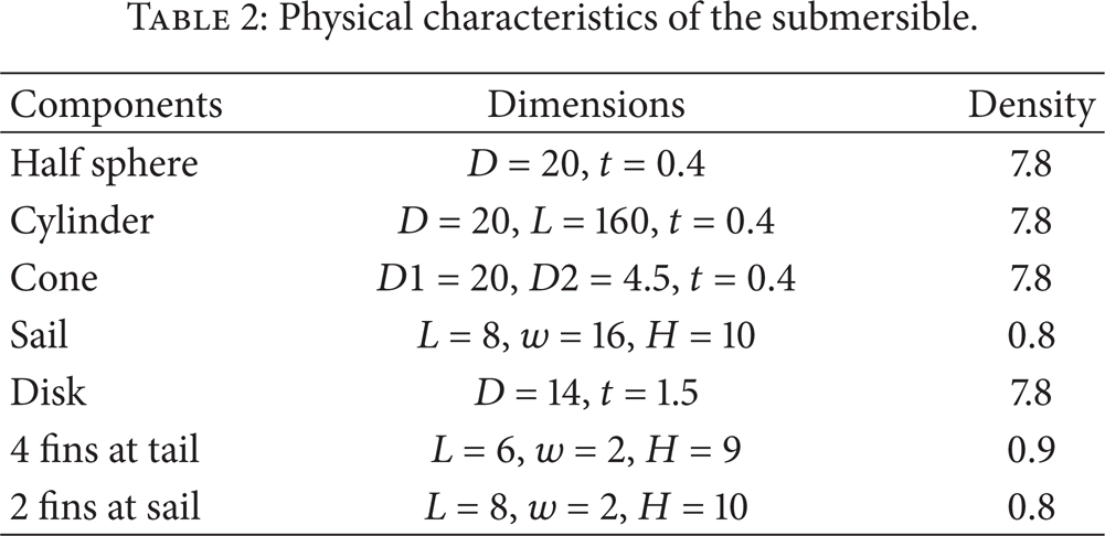
Any submersible that puts to sea is at risk of taking on water, and the most common causes of flooding are collision, grounding, and underwater attack [8]. A submarine-like submersible was used to show the feasibility of the present computational model to investigate such consequences. Figure 6 shows the configuration and mesh system of the submersible with the ratio of length to diameter of 9.5 and the propeller modeled by a disk. The physical characteristics are tabulated in Table 2, where D, t, w, L, H indicate diameter, thickness, width, length, and height, respectively. The ingress length is indicated by L f as shown in Figure 6. By employing the present computational model to simulate a flooding situation, variations of the corresponding properties are depicted in Figure 7. In this figure, the square symbols represent the relation of attitudes (inclinations) in degree versus ingress lengths divided by D. It is noteworthy that there is a steep variation around L f /D = 1.5, which indicates a phenomenon similar to the cylinder flotation as described. The submersible appears nearly level or vertical for most of its range of ingress length, which means the longitudinal position of CG is very sensitive to the trim angle of a surfaced submersible. Moreover, the circle symbol represents the proportion of distance between centers of buoyancy and gravity, BW, in relation to D in gravitational direction while the submersible is taking on water. In practice, the typical submarine proportion for BW in relation to the diameter of the pressure hull is 3 to 4%; and the CG might effectively rise in the transition from submerged to surface conditions [22]. In Figure 7, the CG is above the CB before ingress of water, which is indicated by the circle symbol with a negative value around −15. Nevertheless, the CB becomes further above the CG as more water enters the sinking submersible. Physically, it is more stable when the CB is above the CG because a small inclination of heel or trim produces a restoring couple. But normally W lies above B in the intended attitude for surface vessels like ships. The reasons are as follows. (i) It would be easier to contrive, and (ii) the vessels concerned would not be uncomfortably “stiff” and would sustain small inertial forces in its upper works as a consequence [1]. The triangle and diamond symbols represent the shift over diameter in percentage for the CB after ingress of water in longitudinal and transverse directions, respectively. Clearly, the shift of the CB in lateral direction is not obvious as expected. However, the shift of the CB in longitudinal direction is abrupt over L f /D = 1.5. This means the attitude dynamics of a flooding submersible are strongly related to the buoyancy-center shift longitudinally rather than in lateral direction. A basic issue in the design of a submarine is the provision of high strength bulkheads to isolate selected parts of the hull and so limit the extent of flooding throughout the hull in the event of an accident. The present simulated results may help the preliminary concept for escape policy in submarine design [23].
Physical characteristics of the submersible.
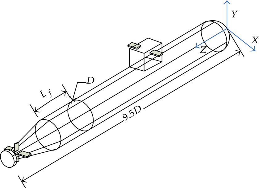
Physical model for simulating attitudes of the submersible.

Property variations for the submersible with various amounts of water admitted.
4. Numerical Simulator
Similar to numerical wind tunnel, it is desirable to simulate the water tank experiment for body floatation by the present computational model so that the procedure can be performed like a numerical simulator [16, 17].
4.1. Analytical Data Base of a Cylinder
The attitude dynamics (θ) of a cylinder related to parameters ω, η′, δ, and L/D of (4) has been thoroughly investigated [19]. It implies that the data base can be established without difficulty. The inclinations of a floating cylinder can be illustrated or tabulated in terms of other parameters, that is, varying parameters by fixing another one. The properties of a floating cylinder thus can be constructed by numerical tables. Figure 8 shows one of the results, which illustrates the relations between the attitude angle and the weight magnitude for various radial positions of CG at a specific position of longitudinal CG (L/D = 9.279, δ = 4). Thus, when the floating attitude angle of a cylinder in the tank has been obtained, the corresponding CG can be predicted by interpolating among known parameters, such as θ and ω. Table 3 displays the results from several examples and demonstrates the feasibility of applying this concept, which is similar to the reverse engineering process. In Table 3, θ and ω are measured from experiment for given L/D and δ (L/D = 9.279, δ = 4, ω = 8.3 for this case), then the required η′ can be obtained by linear interpolation from the data sheet in Figure 8. In other words, this process can avoid the difficulty of experimentally obtaining the distance of CG in a radial direction.
Predicted locations of CG for cases L/D = 9.279 and δ = 4.


Comparison of θ against ω for various η′ with δ = 4 and L/D = 9.279.
4.2. Numerical Data Base for a General Body
Before going further to employ the concept of acquiring the position of CG of a specific body, several cases for the bodies with the same configuration but different positions of CG, cases A to F, have been demonstrated via experiments and the numerical techniques described previously. The relative error percentages for five cases, including inclination angle (E a ) and locations of CG (E l ), by comparing experimental results with computations are listed in Table 4. The comparisons are satisfactory and the errors can be further reduced when much smaller elements are introduced in the computations for same cases. Based on Table 4, a database of properties for a specific body could be constructed. In other words, when the computational model has been experimentally validated and theoretically verified, it can be used to build a database, including various attitudes and locations of CG et al., without the need of costly experiments. Once we know the locations of CG for a specific body, conversely we can obtain the attitude angle by using interpolation techniques in the data base. Theoretically speaking, the data base can be numerically tabulated without difficulty. With the longitudinal direction specified on the body; for instance, the CG variation can be achieved for fixed weight magnitude by longitudinally varying the density value element by element. The whole data table thus can be constructed numerically by individually changing either density value or changing fixed weight magnitude. Generally speaking, a real body can be decomposed to components, which then can be numerically defined as objects and given individual properties. After completing the numerical database, the relevant properties of a body, such as the coordinates of CG, can be acquired by applying 2D linear interpolation techniques to other known properties in the data tables. Obviously, the accuracy of the required property depends on how fine is the mesh system for the computational model. Moreover, a finer mesh system also helps to locate which region in the data table is more appropriate for applying the interpolation to quickly get the required property. Furthermore, the computing time of each parameter run by the present computational model is very short since powerful personal computers can be employed. The present method could thus play a role in acquiring properties for a floating body instead of using costly experiments.
Comparison of experiments and computations.

5. Concluding Remarks
Based on the theoretical and numerical results, several conclusions are drawn below.
A correlation for predicting the inclinations of floating slender bodies, with biased center of gravity negligible, has been described and proved to be feasible.
As a benchmark, the inclinations of a floating cylinder in wide range of angles were demonstrated theoretically and experimentally. For a floating slender body, such as a cylinder or a submersible vessel, the inclination is sensitive to the longitudinal movement of its center of gravity around certain critical locations.
For a flooding submersible that is taking on water dynamically, there exists an abrupt inclination angle variation at the point where a certain amount of water has entered. The center of buoyancy becomes further above the center of gravity as more water enters the submersible. During flooding, the shift of the center of buoyancy in lateral direction is not obvious. Moreover, the longitudinal shift of the CB is abrupt at a certain point.
The analytical data base of a floating cylinder was built. Afterward a numerical water tank was constructed by virtue of the present computational model. As the bank of properties for a specific floating body is built, its position of center of gravity can be obtained conversely by interpolations from known attitudes in data tables.
Conflict of Interests
The authors declare that there is no conflict of interests regarding the publication of this paper.
Footnotes
Acknowledgment
Financial assistance provided by Ministry of Science and Technology in Taiwan, under the contract number NSC93-2611-E-214-001, was greatly appreciated.