
Abstract
A compact linear positioning stage using one microgripper and one piezoelectric stack is presented based on the parasitic motion principle. Characteristics of the linear positioning stage along the positive y-axis and the negative y-axis are measured and compared with each other. Experimental results indicate that the linear positioning stage has features of the large motion range, various movement velocities and stepping displacement, and forward and reverse movements. Meanwhile, the positioning stage has good resolution and enough load capacity. Possible reasons leading to nonlinearity and velocity difference between forward and reverse movements are discussed. Research results in this paper will make applications of the parasitic motion principle more flexible.
1. Introduction
Precision positioning stages are widely required in scientific research and industrial applications. Precision positioning stages based on piezoelectric stacks and flexure hinge-based compliant mechanisms are playing more and more important roles in scanning systems [1], precision and ultraprecision machining [2, 3], micromanipulators [4, 5], micro/nanomechanical testing [6, 7], and so on. For different application requirements, kinds of driving principles have been proposed, such as the piezoelectric stack direct driving principle [8], the inchworm driving principle [9], the impact driving principle [10], and the stick-slip driving principle [11].
Up to now, improving positioning accuracy and increasing the motion range are two important research topics for piezodriven positioning stages [12, 13]. But they are usually conflicting. As a modified stick-slip driving principle, the parasitic motion principle (PMP) which has the potential to solve both of these two issues was presented in [14]. Based on the parasitic motion principle, the microgripper is used to modulate the output of the piezoelectric stack instead of directly piezodriven form stick-slip style. With the symmetrical structure, the PMP linear actuator in [14] mainly consisting of two microgrippers and two piezoelectric stacks realizes the large motion range, various velocities, and forward and reverse movements. However, the symmetrical structure also increases dimensions of the PMP linear actuator, and its size reaches 130 mm × 50 mm × 26 mm, which lowers the flexibility of its applications. For example, the dimension along y-axis of the in situ scratch testing device in [6] is strongly dependent on dimensions of the PMP linear actuator. If dimensions of the PMP linear actuator can be reduced but its functions still maintained, applications of the PMP linear actuator will be more flexible. Based on this consideration, we will try to use only one microgripper and one piezoelectric stack to realize similar functions of the PMP linear actuator [14] in this paper.
2. Structure
Figure 1 is the model of the linear positioning stage based on the parasitic motion principle. In order to reduce repeated design, the microgripper of this linear positioning stage is the same to that of the PMP linear actuator in [14]. Compared with the structure of the PMP linear actuator in [14], the biggest difference in Figure 1 is that only one microgripper and one piezoelectric stack are used, which makes dimensions of the linear positioning stage reduce to be 81 mm × 50 mm × 21 mm. In order to reduce weight of the positioning stage and meanwhile improve electromagnetic compatibility with scanning electron microscopes, materials of the microgripper and the mover were changed to be Al 7075. In addition, more compact linear guide (BWU 17–30, IKO) was selected to reduce weight and dimensions of the positioning stage. Of course, for specific applications, dimensions of the linear positioning stage can be further reduced by optimizing structures and dimensions of the base and the microgripper.

Model of the linear positioning stage.
3. Output Characteristics along the Positive y-Axis
Because the structure of the linear positioning stage shown in Figure 1 is similar to the half of the PMP linear actuator in [14] whose output ability has been verified, movement of the mover along the positive y-axis is undoubtedly feasibility. Considering that materials and linear guide have been changed which will further change friction between the slide block and the guide rail and friction between the mover and the microgripper, output characteristics of the linear positioning stage shown in Figure 1 along the positive y-axis were retested. Figure 2 is the driving wave, and Figure 3 illustrates the experimental results. Figure 3(a) gives output characteristics of the mover along the positive y-axis with a fixed driving voltage of 100 V and different driving frequencies, and Figure 3(b) gives output characteristics along the positive y-axis with a fixed driving frequency of 6 Hz and different driving voltages. With the driving voltage of 100 V and the driving frequency of 10 Hz, effective displacement of the mover along the positive y-axis reaches 663.98 μm after 5 seconds. So, forward movement velocity of the mover is 132.8 μm/s when the driving voltage is 100 V and the driving frequency is 10 Hz.

Driving wave for the movement along the positive y-axis.

Output characteristics of the mover along the positive y-axis with (a) a fixed driving voltage of 100 V and different driving frequencies and (b) a fixed driving frequency of 6 Hz and different driving voltages.
4. Output Characteristics along the Negative y-Axis
Figure 3 further addresses that the linear positioning stage realizes the movement along the positive y-axis. So, the next question is that whether or not the linear positioning stage shown in Figure 1 still has the ability to realize the movement along the negative y-axis which is the reason why the symmetrical structure of the PMP linear actuator in [14] was designed. Next, we will answer this question via experiments.
The movement along the positive y-axis is realized using the driving wave with a portion of the voltage slowly increasing and a portion of the voltage quickly decreasing as shown in Figure 2. Considering that deformation of the microgripper is symmetrical when the driving voltage of the piezoelectric stack increases and decreases, so, whether or not the mover can realize the movement along the negative y-axis by changing the driving wave to be with a portion of the voltage quickly increasing and a portion of the voltage slowly decreasing as shown in Figure 4? Taking this idea, similar experiments were carried out for the reverse movement. In order to compare with the forward movement, same experimental conditions were selected and the experimental results are shown in Figure 5. Figure 5(a) gives output characteristics of the mover along the negative y-axis with a fixed driving voltage of 100 V and different driving frequencies, and Figure 5(b) gives output characteristics of the mover along the negative y-axis with a fixed driving frequency of 6 Hz and different driving voltages. From Figure 5, the conclusion can be addressed that the linear positioning stage shown in Figure 1 completely has the ability to realize the movement along the negative y-axis by the driving wave shown in Figure 4. Similar to the forward movement, stepping displacement and movement velocity of the reverse movement can be easily changed by changing the driving voltage and the driving frequency. With the driving voltage of 100 V and the driving frequency of 10 Hz, effective displacement of the mover along the negative y-axis reaches 763.53 μm after 5 seconds. So, reverse movement velocity of the mover is 152.7 μm/s when the driving voltage is 100 V and the driving frequency is 10 Hz.

Driving wave for the possible reverse movement.
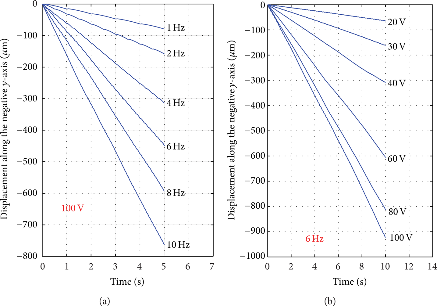
Output characteristics of the mover along the negative y-axis with (a) a fixed driving voltage of 100 V and different driving frequencies and (b) a fixed driving frequency of 6 Hz and different driving voltages.
5. Velocity Characteristics
For further comparing the velocity characteristic between the forward movement and the reverse movement, movement velocity versus the driving frequency and movement velocity versus the driving voltage are illustrated in Figures 6(a) and 6(b), respectively. In Figure 6, movement velocity increases with increasing of the driving frequency and the driving voltage for both the forward movement and the reverse movement, but nonlinearity exists in these curves. In addition, for the same experimental condition, movement velocity of the reverse movement is a little larger than that of the forward movement. In order to reveal possible reasons, initial status between the mover and microgripper was measured by an optodigital microscope (DSX 500, Olympus) and the experimental result is given in Figure 7, from which we can see that manufacturing and assembling errors lead to change of the initial gap between the mover and the microgripper in different contact regions and further lead to nonlinearity of the curves and velocity difference for the forward movement and the reverse movement at the same experimental condition in Figure 6. From another perspective, the linear positioning stage has low manufacturing and assembling requirements. These problems do not affect applications of the linear positioning stage in some places such as applications in in situ micro/nanomechanical testing in [6], which just requires the large motion range, various movement velocities and stepping displacement, and forward and reverse movements. Of course, for specific applications requiring high repeat positioning accuracy, improving manufacturing and assembling quality can further improve its output performances.
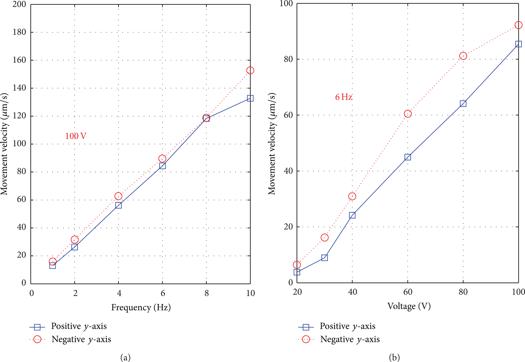
Comparison between forward movement velocity and reverse movement velocity of the mover under (a) the same driving voltage of 100 V and (b) the same driving frequency of 6 Hz.

Initial status between the mover and microgripper.
6. Resolution Characteristics
The resolution, the minimum stable step size, is another important parameter for the micropositioning stage. From Figures 3 and 5, output characteristics of the positioning stage can be easily changed by changing the driving frequency and the driving voltage, which means that the resolution of the positioning stage depends on the driving frequency and the driving voltage. With the driving frequency of 1 Hz, lots of experiments were carried out to obtain the critical driving voltage, and results indicate that when the driving voltage is lower than 12 V, the mover can not move stably for a large range along the positive y-axis, and when the driving voltage is lower than 11.6 V, the mover cannot move stably for a large range along the negative y-axis. The resolution testing curve of the positioning stage along the positive y-axis with the driving frequency of 1 Hz and the driving voltage of 12 V is shown in Figure 8(a), and the resolution testing curve of the positioning stage along the negative y-axis with the driving frequency of 1 Hz and the driving voltage of 11.6 V is shown in Figure 8(b). The accumulated displacements of the mover along the positive y-axis and the negative y-axis are 0.93 μm and 1.1 μm, respectively, corresponding to 10 steps. So, the resolutions of the positioning stage along the positive y-axis and the negative y-axis are 93 nm and 110 nm, respectively. Of course, the resolution can be improved by optimizing the structure of the microgripper, which is not the emphasis of this paper and will be discussed together with the backward movement in another paper.

The resolution testing curve of the positioning stage (a) along the positive y-axis with the driving frequency of 1 Hz and the driving voltage of 12 V and (b) along the negative y-axis with the driving frequency of 1 Hz and the driving voltage of 11.6 V.
7. Loading Capacity
Loading capability is another feature for practical applications of the positioning stage. Via experiments, loading capabilities of the positioning stage along the positive y-axis and the negative y-axis were measured. Figure 9 is the experiment setup. By the pulley and standard weights, various loads along the positive y-axis were loaded on the mover, and then output characteristics of the mover along the positive y-axis and the negative y-axis with the driving voltage of 100 V and the driving frequency of 1 Hz were measured. Experimental results are illustrated in Figure 10.

The experiment setup for measuring loading capabilities of the positioning stage.

Output characteristics of the mover along (a) the positive y-axis and (b) the negative y-axis with different loads. During experiments, the driving voltage and the driving frequency are 100 V and 1 Hz, respectively.
Figures 10(a) and 10(b) illustrate displacements of the mover along the positive y-axis and the negative y-axis, respectively, corresponding to 10 steps. In Figure 10(a), when the applied load increases from 0 N to 1 N, the accumulated displacements of the mover along the positive y-axis increase from 127.08 μm to 154.82 μm. That is to say, the applied load increases one step displacement of the mover along the positive y-axis. On the contrary, the applied load decreases one step displacement of the mover along the negative y-axis in Figure 10(b). The main reason is that direction of the load is the same to direction of the movement of the mover for the positive y-axis, while it is opposite for the negative y-axis. But for both the positive y-axis and the negative y-axis, the mover moves stably when the load changes from 0 N to 1 N, and it can satisfy the requirements for applications in in situ nanoindentation and scratch testing inside the scanning electron microscope whose loads are usually less than 0.5 N [6].
8. Conclusions
In summary, we have designed a more compact linear positioning stage using one microgripper and one piezoelectric stack based on the parasitic motion principle. Experimental results indicate that the linear positioning stage still has the ability to realize the large motion range, various movement velocities and stepping displacement, and forward and reverse movements. Output characteristics of the linear positioning stage along the positive y-axis and the negative y-axis are similar but small difference exists because manufacturing and assembling errors lead to change of the initial gap between the mover and the microgripper in different contact regions. For both the positive y-axis and the negative y-axis, the mover moves stably when the load changes from 0 N to 1 N. Taking features mentioned above especially the more compact structure compared with that in [14], applications of the positioning stage will be more flexible.
Conflict of Interests
The authors declare that there is no conflict of interests regarding the publication of this paper.
Footnotes
Acknowledgments
This research is funded by the National Natural Science Foundation of China (Grant no. 51275198), Special Projects for Development of National Major Scientific Instruments and Equipments (Grant no. 2012YQ030075), National Hi-tech Research and Development Program of China (863 Program) (Grant no. 2012AA041206), Program for New Century Excellent Talents in University of Ministry of Education of China (Grant no. NCET-12-0238), Specialized Research Fund for the Doctoral Program of Higher Education (Grant no. 20130061110026), and Patent Demonstration Project for Research Team in Jilin Province (Grant no. 20130061110026).