
Abstract
The complex motorcycle wheel components of AM50A magnesium alloy had been formed by double control forming and die casting, respectively. The surface quality of components formed by double control forming was much better than die casting parts. When double control forming was used to replace die casting to form motorcycle wheel components, the tensile strength increased from 149.4 MPa to 207.0 MPa and the elongation increased from 5.6% to 10%. The fracture mode was transformed from brittle one of die casting parts to ductile one of double control forming parts. The average grain sizes in the spoke region and the hub region of double control forming wheels were 16 μm and 20 μm, respectively, which were smaller than those of die casting components. The matrix phase of the spoke part was α-Mg, the second phase was Mg17Al12. A fishbone morphology of the second phase of die casting parts was found in the grain boundaries. The second phase of double control forming parts was like needle or rod presence at the grain boundaries. The thickness and spacing twinning in double control forming components became smaller.
1. Introduction
On the view point of material structure, the main method to achieve lightweight production is to use the lightweight material with high performance to replace traditional materials. Magnesium alloys are being widely used to achieve lightweight structural and functional components due to the lowest density of the structural metals, the higher specific strength, and the higher vibration damping [1–5]. Currently, low-pressure die casting (LPDC) and high-pressure die casting (HPDC) are the two common ways of casting for fabricating Mg parts with complex geometries. However die casting magnesium alloy components hold the solidification shrinkage cavity and gas porosity, leading to lower mechanical properties compared with forging Mg parts. Moreover, components formed by die casting cannot have been further heat treated to improve mechanical properties. Lee et al. [6] have proved that the application of intensification pressure, the decrease in the gate velocity, and the decrease in the temperature can reduce the total amount of porosity via reduction in the gas porosity. Fu et al. [7] figured out that using LPDC process can produce high-integrity AM50 casting with higher ultimate tensile strength and elongation. By numerical simulation, Lee and Gokhale [8] made a suggestion that the formation of shrinkage porosity was caused by the presence of gas which can retard heat transfer and change the solidification rate. Also, scholars have discussed the relationship between microstructure and mechanical properties. According to Hall-Petch equation, the flow stress depends upon average grain size [9]. Biswas et al. found that the average yield strength is related to the average pore size [10].
Forging is also an alternative technology for fabricating magnesium components which can achieve higher mechanical properties and finer grain sizes. Xia et al. [11] reported that the initial grain size of AM50A magnesium components formed by isothermal multiaxial forging technology decreases from 148 μm to 14 μm. The cold preforging conducted before extrusion can enhance the tensile strength and elongation by refining the grain and suppressing twinning [12]. While magnesium is close-packed hexagonal structure with less slip systems and has higher deformation resistance, Jiang et al. [13] proposed a double control forming technology combining the die casting and forging technology. The components formed by double control forming (DCF) hold fine and uniform microstructure without defects [14] and achieve higher mechanical properties compared with die casting (DC) parts [15].
Double control forming has exhibited a significant advantage in enhancing mechanical properties and densifying the microstructure of AZ91D and AM60B alloy components. However, influence of DCF on microstructure and mechanical properties of AM50A components was reported to be little. Hence, in this paper, AM50A magnesium alloy components have been achieved by double control forming (DCF) and die casting (DC). It is aiming to analyze the impact of the DC and DCF on the mechanical properties and the microstructure of AM50A magnesium alloy components.
2. Materials and Methods
The commercial AM50A Mg alloy was used as experimental material. An AXIOS-PW4400 X-ray fluorescence spectrometer was employed to measure the composition of AM50A Mg alloy. The AM50A Mg alloy contained 5.90 wt% Al, 0.285 wt% Mn, 0.125 wt% Zn, 0.121 wt% Si, 0.003 wt% Fe, 0.004 wt% Cu, 0.003 wt% Ni, and balance of Mg. The AM50A magnesium alloy components were formed by the double control forming (DCF) machine [13]. A typical magnesium alloy motorcycle wheel component was used as the forming object parts, as shown in Figure 1. A three-factor and four-level orthogonal test was designed, as shown in Table 1. Three factors involved pouring temperature, injection speed, and die temperature. Four levels were determined according to the practice of die casting. The forging force of DCF was set to 4000 kN. DC experiments were also carried out in the same condition to compare the difference of microstructure and mechanical properties between DCF and DC. 32 typical wheels were manufactured by double control forming (DCF). 32 parts were formed by die casting (DC) to compare the difference of microstructure and mechanical properties between DCF and DC components. The tensile samples were cut from position A (Figure 1) and prepared according to ASTM, B557 M-94 [16].
Process parameters of double control forming of AM50A magnesium alloy components.


Three-dimension modeling of the motorcycle wheel.
Tension tests were carried out on the Instron 5569 material testing machine with the speed of 2 mm/min. A load of 10 kgf was loaded on the sample to measure the micro-Vickers hardness of Mg products by the Tester HVS-1000Z. The microstructure samples were cut from positions A and B.
Microstructure samples were etched in a solution of 5 g picric, 5 mL acetic acid, 10 mL distilled water, and 90 mL ethanol for 10 seconds. The grain size and shape factor were observed by using an Olympus G50 optical microscope and Quanta 200FEG field emission scanning electron microscope. The transmission experiments samples were taken from the tension sample and ground to specimen with a thickness of 100 μm. The final transmission specimen manufactured by double-jet electrolytic polishing under the temperature of −35°C was used to survey the dislocation and twinning in the Mg parts of DC and DCF by field emission transmission electron microscopy Tecnai G2F30.
3. Result and Discussion
3.1. Mechanical Properties of the Component Formed by DC and DCF
Figure 2 shows AM50A Mg alloy motorcycle wheel components produced by die casting (DC) and double control forming (DCF) under the L1 experiment parameters. The L1 experiment parameters involved the pouring temperature of 675°C, the injection speed of 3 m/s, and the mold temperature of 230°C. The component of AM50A magnesium alloy formed by DCF possessed much better surface quality compared with die casting components. In particular, the surface of the spoke of the component formed by DCF is smoother than that of the component formed by DC. It is because that high pressure caused by forging procedure can make the surface of the spoke smooth and dense. In addition, rim of the component formed by double control forming has better surface quality as compared with the die casting component. It is due to the fact that the rim region undergoes a high-pressure extrusion transferred by forging procedure in the spoke region.

AM50A Mg alloy component produced by (a) DC and (b) DCF.
Table 2 reveals ultimate tensile strength (UTS) and elongation of the AM50A magnesium alloy parts. The tensile samples were taken from the spoke of the wheel, which is the main part of bearing the load in the wheel. The average UTS and elongation of the components formed by DCF are 207.0 MPa and 10.0%, respectively. However, the average UTS and elongation of the components formed by DC are 149.4 MPa and 5.6%, respectively. The Vickers hardness of the components formed by DCF was improved significantly as compared with die casting components. The AM50A magnesium alloy components manufactured by DCF hold higher mechanical properties than the components formed by DC. Within a reasonable range of other parameters, the UTS of the Mg alloy components formed by DCF has not changed obviously with the changes in pouring temperature, injection speed, and mold temperature. But the UTS of the goods produced by DC changes from 104.5 MPa to 187.6 MPa under the same conditions, which means the UTS of DC products is more sensitive to the changes in process parameters. This obvious change of mechanical properties of the component formed by DC demonstrates that die casting is not stable for forming the AM50A motorcycle wheel component.
Mechanical properties of AM50A Mg alloy components formed by DC and DCF at room temperature.

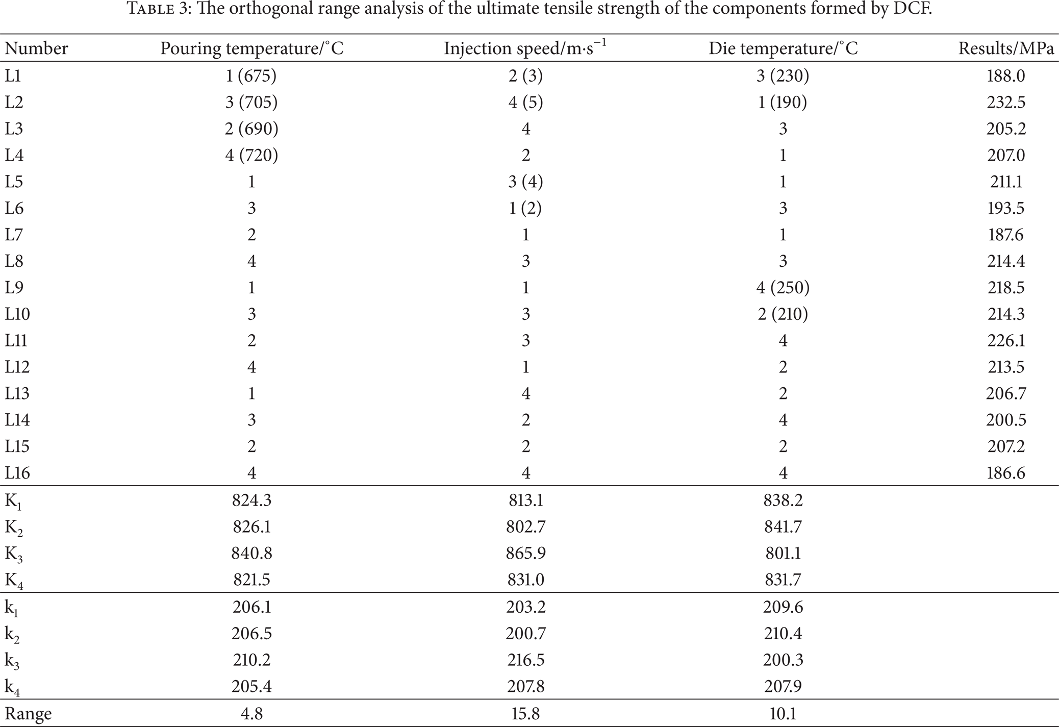
In addition, the primary and secondary levels of the experimental parameters can be Figured out by the analysis of ultimate tensile strength single indicators, as shown in Table 3. A high UTS value reveals a better combination of pouring temperature, injection speed, and die temperature. So the optimal solution can be determined by the level which corresponds to maximum value of each factor, K1, K2, K3, and K4 (or k1, k2, k3, and k4). By calculating the range table, it is shown that the optimal solution of experimental parameters is the third level of pouring temperature, the third level of injection speed, and the second level of die temperature. The optimum parameters forming the AM50A magnesium alloy motorcycle wheel are L10, in which the pouring temperature is 705°C, the injection speed is 4 m·s−1, and the die temperature is 210°C. The increasing order of range is injection speed, die temperature, and pouring temperature. So the pouring temperature shows little effect on the performance of the spoke sites followed by die temperature. The injection speed has much influence on the results of the experiments. The injection speed is the most sensitive parameter and the pouring temperature is the more stable parameter. Similar results can be obtained by the analysis on elongation range.
The orthogonal range analysis of the ultimate tensile strength of the components formed by DCF.
The tensile fractures of the parts formed by DC and DCF are shown in Figure 3. Some obvious nonfracture zones were found in the fracture of the component formed by DC (Figure 3(a)). Similar phenomenon was also found in the AM60 magnesium alloy [15]. These nonfracture zones are shrinkage cavity (or microporosity), which decrease mechanical properties of the component formed by DC.

The tensile fracture of magnesium alloy component formed by (a) DC and (b) DCF.
Figure 3(b) presents the fracture with quite number of dimples with tear ridges which is the main morphology of metal ductile fracture. The tensile fracture morphology of components formed by DCF almost had no pores and cracks. It indicates that the internal pores and cracks of the DC parts can be welded together or eliminated and the grain can be refined by applying force in the semisolid state of the DCF parts. It will increase the mechanical properties of the component formed by double control forming.
3.2. Microstructure of the Components Formed by DC and DCF
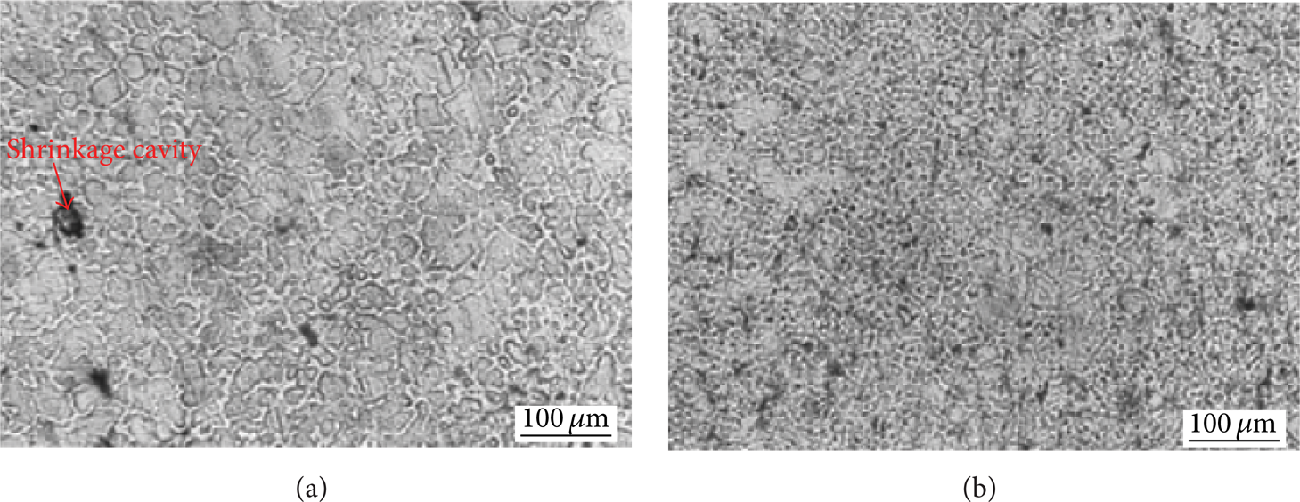
Figure 4 shows the microstructure of the components formed by DC and DCF. Figure 4(a) is the micrograph of the spoke of the wheel component, indicating an average size of 30 μm. The thinnest wall thickness of the spoke portion is 5 mm and the cooling rate is relatively high during die casting. A relatively high cooling rate can lead to an increase of nucleation rate during the solidification. As a result, relative fine grains were obtained in the spoke region of the component formed by DC. The average grain size in the spoke region of the components formed by DCF is 16 μm (Figure 4(b)), indicating a further refinement as compared with die casting component.

The microstructure of the spoke of the wheels (position A) formed by (a) DC and (b) DCF.
The forge force applied to the liquid-solid slurries increases the conduction rate between die and liquid-solid slurries, leading to a larger undercooling degree as compared with die casting. As a result, a large number of crystal nucleuses were created in the melt and the grains were refined. In addition, the solid dendrites were fragmented due to plastic deformation during the final solidification stage and the grains were refined. The thickness of the spoke portion is gradually reduced and the contact area of the spoke and the mold gets smaller from the center portion to the rim. The pressure on the spokes from the center to the rim portion is increased under the same forging force. It means that the dendrites are fragmented better and the grain size is smaller. Thereby the mechanical properties of the spokes have been improved.
The average grain size of the center portion (position B) of the wheel formed by DC is 60 μm (Figure 5(a)). Some obvious shrinkage cavity was found in the microstructure. The center portion in the hub region holds the maximum wall thickness and is the last solidified part of the solidification process. The temperature of the center is higher and the solidified metal is difficult to get feeding. So the grain size is larger than other positions and the shrinkage porosity is significant. The micrograph of the wheel formed by DCF is greatly improved (shown in Figure 5(b)). The average grain size is 20 μm, significantly smaller than the grain size of the components formed by DC under the same experimental parameters. The liquid metal surface energy decreased under the pressure of forging force and the latent heat of crystallization rose. So the critical nucleation radius decreased and more radicals are involved in the nucleation. Because of the presence of the forging pressure, the molten metal in front of the solidification metal is forced into the gap caused by solidification shrinkage and achieves the effect of feeding. Further, the dendrite solidification is broken by the formation pressure. The broken dendrite plays the role of nuclei in subsequent solidification so that the final grain has been refined and holds uniform grain size.
The microstructure of the center of the wheels (position B) formed by (a) DC and (b) DCF.
The EBSD technique can directly count the number of grains of different grain sizes and output the distribution [17]. Figure 6 shows the impact of different forming processes on the grain size and the misorientation angle. As shown in Figures 6(a) and 6(b), the difference in grain size of the component formed by DC is smaller than that of the component formed by DCF. Some finer grains were found in the EBSD microstructure of the component formed by DCF as compared with that of the component formed by DC. Small-angle boundaries of the component formed by DCF were more than those of the component formed by DC (Figures 6(c) and 6(d)).

The EBSD analysis of the components formed by DC and DCF under the experimental parameters of L8 (a) microstructure of DC component, (b) microstructure of DCF component, (c) misorientation angle of DC component, (d) misorientation angle of DCF component, (e) grain size of DC component, and (f) grain size of DCF component.
In the DCF process forging force applied to liquid-solid slurries caused some plastic deformation of solid grains during the final solidification stage. As a result, some dislocations were created due to plastic deformation. These dislocations can be rearranged due to their nonstable energy status, leading to formation of some small-angle grain boundary. The grain size of the components formed by DC is mainly in the range of 6 μm to 30 μm (Figure 6(e)). The grain size of the components formed by DCF is mainly in the range of 4 μm to 30 μm (Figure 6(f)). Furthermore, the number of fine grains less than 5 μm of the component formed by DCF was higher than that of the component formed by DC. Some new fine grains were created in the grains due to dynamic recrystallization caused by plastic deformation during the DCF process, which was illustrated by Figure 6(b). In addition, the presence of forging force elevates the melting points of magnesium alloy and enlarges the supercooling degree, which increases the power of heterogeneous nucleation. So the grain size of the components formed by DCF becomes smaller.
Figure 7 is the energy spectrum of the second phase of the specimen taken from the components formed by DC under the experimental parameters of L16. The XRD result shows that the main component of the second phase of AM50A magnesium alloy is Mg17Al12. In addition, a small amount of Zn, C, and O elements gathered in the vicinity of the second phase, indicating that it is likely to be the oxide inclusions along the grain boundary. The second phase has large size and reduces the grain boundary strength. The matrix phase of AM50A magnesium alloy is α-Mg and the content of C atoms increases relative to the second phase. The contents of Al and O elements in the junction of the matrix and the second boundary increase compared to the location in the matrix and make the junction brittle and weak.

The second phase energy spectrum of AM50A Mg alloy: (a) location, (b) spectrum curve, and atomic spectroscopy content.
It can be found in Figure 8(a) that the second phase Mg17Al12 shaped fishbone distributed along the grain boundary unevenly. The brittle second phase reduced the strength of the material and result in brittle fracture of the material occurs during stretching the specimen of the components formed by DC. Figure 8(b) shows that the acicular or rod-like second phase dispersed in the grain boundaries and the matrix uniformly. The strength and toughness of the organization have been enhanced. The components formed by DCF hold relatively small microstructure and uniform grain.
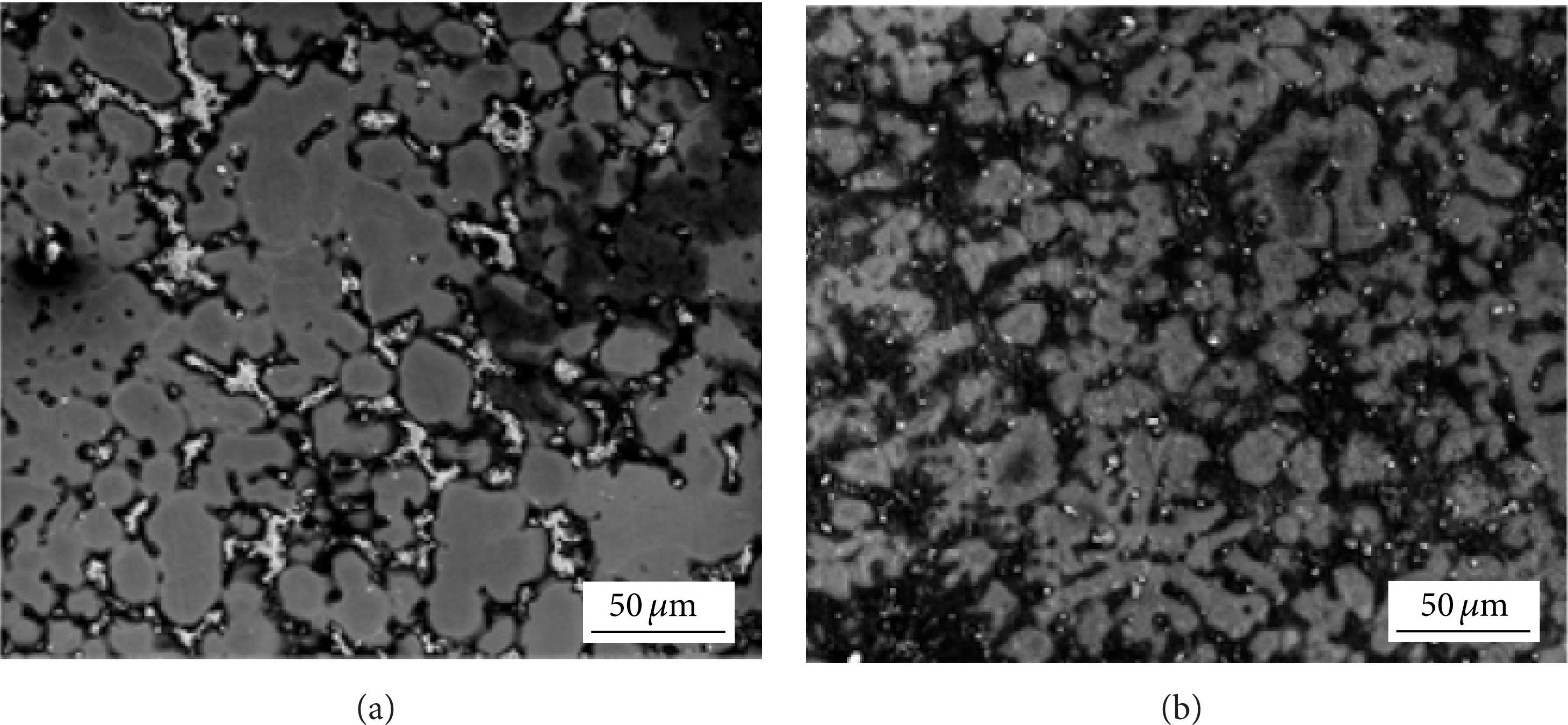
The SEM microstructure of the wheel central parts formed by (a) DC and (b) DCF under the experimental parameter of L7.
The solute atoms interact with the matrix and are distributed unevenly. Due to the coherent relationship between the interface of the matrix and second phase, the second phase caused the lattice distortion in the matrix. There exists a stress field around the second phase. The second phase particles and stress field around itself impede the movement of dislocations during the plastic deformation of the alloy. Mg17Al12 is a brittle phase and dislocation cuts through the particle from one side to the other side when the second phase encounters dislocations. The second phase produces a new interface after cutting deformation and improves the interfacial energy. Furthermore, the phenomenon of dislocation cutting through the second phase particles is substantially actuated so as to deform the second phase dislocation. The second phase itself has high strength and large force is required to start the dislocation. So the strength of the components is enhanced.
By measuring the differences of grain orientation and the proportion and distribution of different orientations of the grains in the sample, it can be found that the small-angle grain boundaries (<15°) accounted for 20.3% in the specimen of die casting wheel under the experimental parameters of L8 (Figure 9(a)). The small-angle boundaries in the components of DCF under the same experimental parameters increased to 39.5% (Figure 9(b)). The amount of small-angle grain boundary has an effective influence on the mechanical properties. The grain boundary is short stress field and can hinder the lattice dislocation slip into or through the grain boundaries. If the lattice dislocation slips through the grain boundary, the Burgers vector will change and form the grain boundary dislocations. The grain boundary sliding dislocation is formed along the grain boundary when part of the delivery slip. There are two effects caused by the presence of grain boundary which are elastic strain mismatch and plastic deformation strain mismatch. The two effects cause the vicinity of multiple slips along the grain boundary. The elastic strain mismatch effect causes time slip before the primary slip and the forest dislocations constituted by the subsequent grain boundary sliding make the hardening mechanism possible. The adjacent grains have different orientations. The primary slip systems in the adjacent grains are difficult to operate simultaneously under the external force. Grain boundaries can destroy the crystallographic characteristics of the movement dislocations and play a role in strengthening. It proved that the components formed by DCF hold better mechanical properties than the parts formed by DC.

The inverse pole figure of the component formed by (a) DC and (b) DCF under the experimental parameters of L8.
The plastic deformation of magnesium alloy is mainly by dislocation slip and twinning. Figure 10 shows the TEM micrograph of the components formed by DC and DCF under the experimental parameters of L3. The density of dislocation in the sample of DCF increased as compared with DC component. High dislocation density can impede the slide of grains boundary when the component was loaded by external force, leading to enhancement of mechanical properties.
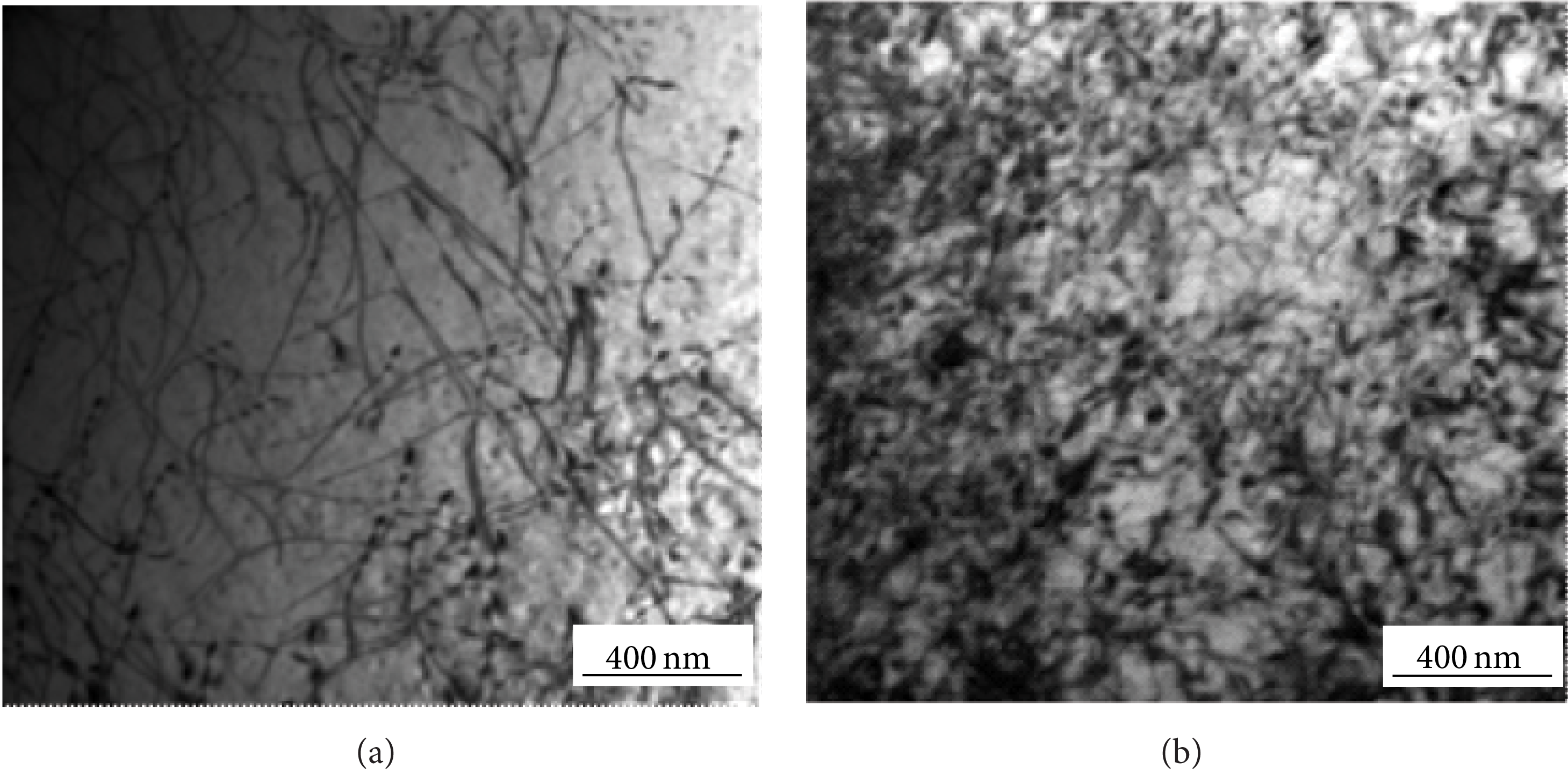
The TEM micrograph of the components formed by DC (a) and DCF (b) under the experimental parameters of L3.
Figure 11 presents the comparison of the twins’ morphology in the components formed by DC and DCF. The pitch and the width of twins in DCF wheel are smaller than the twins in DC wheel. The force of packing stage in DC is smaller and has few influences on the solidification of Mg alloy. The density of dislocation is low and the width of twins is larger as compared with DCT component. For magnesium alloy, the critical shear stress of basal slip systems is smaller than nonbasal system (facet slip system
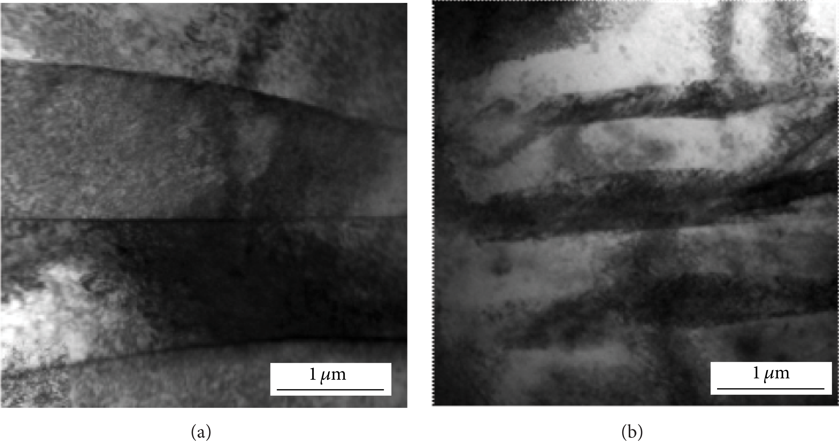
The TEM comparison of the twins’ morphology in the components formed by (a) DC and (b) DCF.
The number of dislocations in the components formed by DCF increased after the deformation and the formation of dislocation motion barriers between dislocations by the intersection and reactions. Dislocation pile-up causes stress concentration and stress field in front of the obstacle. The resistance of dislocation extended during the deformation process increases and the strength of the material will be improved. Twinning can produce some dislocation motion and the twin boundaries are obstacles to dislocation movement which cause dislocation pileup. It makes the stress concentration possible. It can be seen that an increase in the number of dislocations and twinning causes dislocation pile-up and helps produce stress concentration which occurs when the material is deformed. It explains the mechanical properties of components formed by DCF superior to the components formed by DC.
4. Conclusions
The mechanical properties and microstructure of AM50A magnesium alloy components formed by die casting and double control forming have been compared in this research. The reasons why the mechanical properties of DCF components are better than those of DC components were analyzed and the superiority of DCF on grain refinement was illustrated. The following conclusions were drawn.
The surface quality of DCF components is better than that of the DC components. The mechanical properties of the DCF components are significantly higher than those of the DC components. The tensile strength and elongation of the DCF components increased from 149.4 MPa to 207.0 MPa and from 5.6% to 10%, respectively, as compared with DC. Also the hardness of DCF components was higher than that of DC components. Die casting is not stable for forming the AM50A motorcycle wheel component due to obvious change of mechanical properties such as UTS and elongation.
The fracture mode of DC components was brittle fracture and the fracture mode of DCF components was ductile fracture that contained intergranular fracture and cleavage fracture. The fracture of DCF components had a large number of dimples and tear edges. The average grain size in the spoke region of die casting wheels was 30 μm and the average grain size of double control forming wheels was 16 μm. The average grain size in the hub region of die casting wheels was 60 μm and the average grain size of double control forming wheels was 20 μm.
The microstructure of the AM50A magnesium alloy components consists of α-Mg and the second phase is Mg17Al12. The fishbone second phase of DC components was distributed at the grain boundaries. The second phase of DCF components was needle-like or rod-like which was distributed at the grain boundaries. The thickness and spacing of twinning of the magnesium alloy components formed by DCF were smaller and the density of dislocation increased.
Conflict of Interests
The authors declare that there is no conflict of interests regarding the publication of this paper.
Footnotes
Acknowledgments
This work is supported by the National Natural Science Foundation of China (NSFC) under Grant no. 51075099, the Fundamental Research Funds for the Central Universities under Grant no. HIT.NSRIF.2013007, and the Specially Postdoctoral Science Foundation of Hei Longjiang Province under Grant no. LBH-T1102.