
Abstract
Nowadays, wireless sensor networks (WSNs) are used in a variety of areas. However, it is difficult to efficiently manage a large number of sensor nodes and their sensing data owing to the limitations of WSNs. Particularly, in agricultural applications, a WSN installed in a specific region is used for multiple services (i.e., greenhouse environment monitoring and control). However, the network resources (i.e., channel, battery, etc.) are currently being utilized for redundant operations requested from multiple service users owing to the lack of an efficient system for managing large WSN data. In this paper, we propose an agriculture sensor-cloud infrastructure (ASCI) to effectively provide various agricultural services using WSNs. In addition, we propose hierarchical source routing (HSR), aggregation gradient routing (AGR), and a priority-based data transmission technique in order to allow packets to be delivered to the destination fast and reliably in large-scale WSNs.
1. Introduction
Wireless sensor networks (WSNs) are used in various application fields such as military surveillance, healthcare, building automation, precision agriculture, and public safety [1–8]. Among them, precision agriculture is known as a solution for effectively mitigating the problems of food shortage and environmental pollution because it can manage the variability in crop yields by maximizing the production and profitability while minimizing the risk. Many researchers have paid increasing attention to the applicability of WSNs to precision agriculture [5–10] owing to such a potential benefit. In addition, most of the existing works focused on the development of routing and medium access protocols for monitoring and controlling the agricultural environment [9, 10].
Recently, several sensor-cloud infrastructures have been proposed as a remedy for the deterioration of the service performance caused by the limitations of WSNs in terms of memory, energy, computation, communication, and scalability. For efficient management of a large number of WSNs and their data, these infrastructures integrate cloud computing with the WSNs. In particular, because a sensor-cloud infrastructure is an open, flexible, and reconfigurable platform for monitoring and controlling applications [11–13], we believe it to be suitable and beneficial for precision agriculture with large-scale WSNs. The possible services over the precision agriculture system based on the sensor-cloud infrastructure are air/soil monitoring, cultural control for maintaining the growing environments at a constant level, precise monitoring of the growth status, agricultural surveillance, and so forth.
Although several sensor-cloud infrastructures have been envisioned by many researchers, there remain some important issues to deal with, for example, efficient management of sensors, real-time processing and storage of the WSN data, and offering various services: (1) efficient data communication over the physical WSNs, (2) multipath source routing for guaranteeing reliability and fault-tolerance, and (3) hierarchical routing for solving the scalability of the network.
Therefore, we propose a new agriculture sensor-cloud infrastructure (ASCI) for processing large volumes of WSN data as well as providing various types of agricultural services and design a new efficient routing protocol for WSNs belonging to ASCI. The rest of our paper is organized as follows. A brief introduction to existing sensor-cloud infrastructure systems and routing protocols for typical WSNs is presented in Section 2. Section 3 addresses the proposed ASCI. And the proposed multipath routing protocol for large-scale WSNs is described in Section 4. In Section 5, we evaluate the performance of the routing protocol using the ns-2 simulator considering various aspects. Finally, the conclusions are drawn in Section 6.
2. Related Works
2.1. Sensor-Cloud Infrastructure
A sensor-cloud infrastructure is an extended form of cloud computing for managing sensors scattered throughout a network, and its main objective is to collect, store, and process the data from these sensors [14]. In particular, another objective of the sensor-cloud infrastructure is to support a number of services at low cost. In order to achieve these goals, this infrastructure virtualizes physical sensors and allows the users to monitor and control the physical sensors without the knowledge of the deployment of the physical sensors. The provisioning of services from the virtualized sensors is automatically facilitated on demand by users in this infrastructure, and this system monitors the virtual sensors regularly and allows the users to destroy their virtual sensors when they become meaningless. In addition, it also provides a user interface for registering and deleting the physical sensors and admitting the deleting users [15]. In the sensor-cloud infrastructure shown in Figure 1, various functional modules (i.e., virtualization, standardization, automation, monitoring, grouping, service modeling, etc.) should be implemented for the successful realization of large-scale WSNs integrated with cloud computing.

Sensor-cloud infrastructure.
2.2. Sensor Network Routing Protocol
For efficient management of sensors and real-time processing of a large amount of data from sensors, the communication between the sensors should be performed in a fast and efficient manner. Particularly, a WSN for precision agriculture applications consists of hundreds of thousands of sensors, and it should provide reliable communication for sophisticated control of the sensors and actuators. Therefore, a routing protocol for this application should be reliable, fault-tolerant, and scalable with the network size (i.e., the number of sensors).
Currently, there exists a number of routing protocols for WSNs, and they can be classified into flat-based routing, hierarchical-based routing, and location-based routing depending on the network structure [16, 17]. Furthermore, these protocols can be classified into multipath-based, query-based, negotiation-based, QoS-based, or coherent-based routing techniques depending on the protocol operation. Among those protocols, it is known that multipath-based routing protocols can guarantee reliability and fault tolerance through redundant transmissions. It is noted that the multipath-based routing protocol can be further divided into alternative path routing and concurrent multipath routing according to the usage pattern of multiple paths [18].
Recently, the scalable multipath source routing (SMSR) protocol has been proposed to meet the requirements of both reliability and fault tolerance [19]. Figure 2 depicts the basic operation of the SMSR protocol. In SMSR, the source routing approach is used for downstream traffic, and the upstream traffic is delivered to the sink according to gradient-based routing, where the gradient is determined on the basis of the hop count value. In the initialization phase, each sensor acquires the identification of a one-hop neighbor (called the next-hop node) that can relay its upstream packet. The identification of the next-hop node is piggybacked onto the upstream packet, and the packet is transmitted to the next-hop node and finally reaches the sink. The sink collects the next-hop node information and calculates the shortest node-disjoint path toward each sensor. The downstream packet is delivered to this destination according to the source routing on the basis of the shortest node-disjoint path. According to this operation, the SMSR facilitates the shortest routing between each sensor and the sink with low message overhead and allows each sensor to maintain a light-weight routing table.

Scalable multipath source routing.
However, in large-scale WSNs with hundreds of thousands of sensors (i.e., WSNs for precision agriculture), the average length of the paths used in SMSR is relatively long as compared with that in small-scale WSNs. The reliability of packet delivery over the given path decreases as the path length increases. In addition, an excessive amount of traffic from the sensor nodes exacerbates the hot-spot problem. Traditionally, WSNs are composed of a large number of sensor nodes and a single sink. The sensor nodes should transmit their data packets to the sink in a multihop manner because the distance from each sensor node to a sink (except the one-hop neighbor nodes of the sink) is greater than the transmission range of the sensor nodes. Therefore, the sensor nodes near the sink tend to dissipate their energy faster than the nodes located far away from the sink because they have to forward a large amount of data. This uneven energy depletion, known as the hot-spot problem, drastically reduces the lifetime of the sensor networks.
3. System Models and Problem Formulation
3.1. Agriculture Sensor-Cloud Infrastructure
Figure 3 depicts the architecture of the proposed ASCI, which is designed to support various agricultural applications (i.e., air/soil monitoring, cultural control for constantly maintaining the growing environments precise monitoring of the growth status, agricultural surveillance, etc.) with a low cost for the sensor equipment and system operation/management.

Agriculture sensor-cloud infrastructure architecture.
The components of the ASCI are organized in a hierarchical manner consisting of a physical sensor network (physical layer), virtual sensor cloud (virtual layer), and service cloud (service layer). The number of sensors in the physical sensor networks can be up to hundreds of thousands of sensors, and it varies depending on the type of the agricultural applications targeted. Each sensor node is equipped with various sensors (temperature, humidity, electrical conductivity, etc.) and controllers (ventilation, irrigation, etc.). The physical sensors can be registered at the ASCI, and they can be deleted from the system when required by the users. The virtual sensor cloud virtualizes the sensors and controllers. A single sensor or a group of sensors can be virtualized according to the demand of the user. The ASCI provides a user interface for provisioning and destroying the virtual sensors. The service cloud is a layer for providing various services using an individual sensor or a group of virtual sensors. In order to provide various services to the users in a convenient manner, the service cloud exploits the concept of service template. Therefore, a user should select an appropriate service template for a specific service. Furthermore, the service layer accesses the sensors and controllers in the physical layer with the aid of the virtual layer for controlling and monitoring them.
Throughout the service life cycle, the resources (sensors and controllers) in the physical layer are shared by the layers via tasks such as monitoring/controlling, provisioning, destroying, registering, and deleting. In particular, the routing protocols used in the physical sensor network should be reliable, fault-tolerant, and scalable for efficient resource sharing.
3.2. Problem Formulation in the Physical Sensor Network
Figure 4 depicts the structure of the physical sensor network in the proposed ASCI architecture. The physical sensor network has a layer structure in which the upper layer consists of sensor routers with high process capability, and the lower layer includes multiple sensor networks with typical sensor nodes. As shown in Figure 4, each sensor network in the lower layer is used for a specific application. The ASCI does not limit the range of applications. It is noted that the example applications are plant growth information sharing/monitoring and microclimate environment controlling/information sharing.
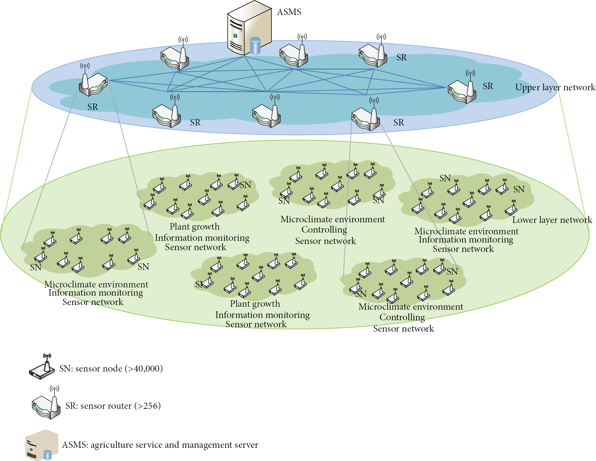
Wireless physical sensor network (physical layer).
The upper layer consists of sensor routers and an agriculture service and management server (ASMS). Each sensor router collects the environmental and growth information from the sensor networks in the lower layer and delivers the collected information to the ASMS. The ASMS manages the sensors and controllers in the physical sensor networks, virtualizes the sensors and sensor networks, and provides the users with various services according to the service life cycle.
The data traffic exchange between the sensor nodes can be categorized into four classes: (1) traffic related to the service life cycle, (2) traffic for managing the sensor networks and traffic carrying information regarding events such as fire, heavy snow, heavy rain, and trespassing, (3) traffic for monitoring and controlling the crop environment, and (4) crop environment and growth status traffic periodically originating from an individual sensor node. The transmission of the first three classes of traffic does not occur frequently; however, it should be performed reliably. On the other hand, the amount of data for the last class of traffic is significantly greater than the others; however, a certain level of loss rate can be considered to be tolerable in this system.
In this work, we extend the SMSR protocol in order to allow it to work properly in the ASCI architecture. In the existing SMSR protocol, the hop length of the path between the ASMS and each sensor node increases with the number of sensor nodes. When a packet is transmitted over a long path, the size of the header specifying the source address can be larger than the size of the payload of the packet. In addition to the message overhead, the packet delivery over the longer path is likely to be exposed to collisions more frequently. In particular, collisions frequently occur around the ASMS because of the hot-spot problem.
Therefore, we propose a hierarchical SMSR (H-SMSR) protocol that uses hierarchical source routing (HSR) and aggregation gradient routing (AGR) in order to overcome the abovementioned problems occurring in large-scale sensor networks. In addition, the H-SMSR exploits priority-based data transmission for mitigating the hot-spot problem.
4. H-SMSR for Agriculture Sensor-Cloud Infrastructure
The operations of the H-SMSR with HSR and AGR are summarized below.
ASMS configures and manages the network of sensor routers (upper layer). Each sensor router configures and manages a typical sensor network in the lower layer. The data packet destined for a specific sensor node (denoted by s) is delivered from the ASMS to a specific sensor router managing s (called one-step source routing). The sensor router delivers the packet to s (called two-step source routing). The packet originating from a sensor node (denoted by s) is delivered to the sensor router managing s according to gradient-based routing. A sensor router aggregates packets from the sensor nodes and delivers the aggregated packet to the ASMS (called aggregation gradient routing). When a node has a packet with the highest priority, it advertises this fact to the neighboring nodes via flooding before it transmits its pending packet.
4.1. Network Configuration
The H-SMSR first configures the network in the upper layer and configures the sensor networks in the lower layer. Figure 5 shows the configuration procedure of the network of the sensor routers. First, the ASMS floods all sensor routers in the network with the ULN_IREQ message. ULN_IREQ includes the address of the ASMS, the number of hops (called the hop count) that the ULN_IREQ message has traversed, and the sequence number. Whenever a sensor router receives a ULN_IREQ message, it updates the routing table (called SR_UpstreamRoutingTable) for upstream packet delivery and it calculates the shortest path to the ASMS according to the greedy forwarding mechanism on the basis of the fields in the received packet. The routing table of the sensor router stores the ASMS address, the address of the next-hop node over the shortest path, the path length of the shortest path, and so forth. After updating the routing table, a sensor router increases the value of the hop count field by one and decreases the value of the sequence number field by one. When the sequence number is equal to zero, a sensor router cancels its rebroadcasting. Otherwise, it performs rebroadcasting of the ULN_IREQ message.

Upper-layer network configuration.
After waiting a predefined time (called T) from the time when the sensor router first receives a ULN_IREQ message, a sensor router transmits a ULN_IREP message to its next-hop node. The ULN_IREP message includes the address of the sensor router, the length of the shortest path, and the address of the next-hop node. The ULN_IREP message is finally delivered to the ASMS according to the next-hop forwarding mechanism. The ASMS collects the ULN_IREP messages from all sensor routers and constructs the routing table for the delivery of the downstream packets according to the source route construction algorithm of the SMSR. It is noted that the sensor routers can provide information on multiple next-hop nodes to the ASMS depending on the performance of the ASMS and the network configuration policy.
Figure 5 shows the configuration procedure for the sensor networks in the lower layer. After configuring the sensor routers, the ASMS allows a sensor router to begin the configuration of a sensor network in the lower layer by flooding the network with the LLN_CREQ message. When the address of the sensor router in the LLN_CREQ message is zero, all sensor routers initiate the configuration. On the other hand, only the designated sensor router initiates the configuration when the address of the sensor router in the LLN_CREQ message is equal to that of a specific sensor router.
A sensor router begins the configuration by flooding the network with the LLN_CREQ message. LLN_IREQ includes the address of the sensor router, the length of the shorter hop path to the ASMS, and the sequence number. Whenever a sensor node receives an LLN_IREQ message, it updates the routing table (called SN_UpstreamRoutingTable) for the delivery of upstream packets and a sensor node calculates the shortest path to the ASMS according to the greedy forwarding mechanism on the basis of the fields in the received packet. The routing table of the sensor node stores the ASMS address, the address of the next-hop node over the shortest path, the path length of the shortest path, and so forth. After updating the routing table, a sensor node increases the value of the hop count field by one and decreases the value of the sequence number field by one. When the sequence number is equal to zero, a sensor node cancels its rebroadcasting. Otherwise, it performs the rebroadcasting of the LLN_IREQ message.
Similar to the sensor routers, each sensor node transmits an LLN_IREP message to its next-hop node after receiving some of the LLN_IREQ messages for a predefined time (called T). The LLN_IREP message includes the address of the sensor node, the length of the shortest path to the sensor router, and the address of next-hop node. The LLN_IREP message is finally delivered to the sensor router according to the next-hop forwarding mechanism. The sensor router collects the LLN_IREP messages from all sensor nodes and constructs the routing table for the delivery of the downstream packets according to the source route construction algorithm of SMSR. It is noted that the sensor routers can provide information regarding multiple next-hop nodes to the ASMS depending on the performance of the sensor router and network configuration policy. After receiving the LLN_IREP messages from all sensor nodes, the sensor router transmits an LLN_CREP message to the ASMS in order to deliver the information about the lower layer to the ASMS. The LLN_CREP message includes the address information of the sensor nodes. The ASMS creates a mapping table (called SR/SN MappingTable) between a sensor router and the sensor nodes belonging to the sensor router and terminates the entire procedure of the network configuration on the basis of the address information.
Figure 7 shows examples of the routing tables. The routing tables of SR7 and SN4 are constructed according to the configuration procedure depicted in Figures 5 and 6. The sensor routers and sensor nodes can exchange the downstream and upstream packets on the basis of these routing tables.

Lower-layer network configuration.

Example routing tables.
4.2. Hierarchical Source Routing
HSR is used for delivering the downstream packets and divides the entire source routing between the ASMS and a sensor node into two steps: source routing between the ASMS and the sensor router and source routing between the sensor router and the sensor node. Through this approach, the HSR can prevent the length of the entire route specified in the packet header from becoming extremely long. For example, as shown in Figure 7, SR/SN MappingTable and SR_DownstreamRoutingTable constructed by the ASMS and SN_DownstreamRoutingTable constructed by SR7 are looked up for delivering the packet from the ASMS to SN4. The ASMS looks up the SR/SN MappingTable in order to determine the sensor router that SN4 belongs to. After determining the appropriate sensor router (i.e., SR7), the ASMS transmits the packet to the target sensor router according to the souring routing mechanism. Finally, SR7 transmits the packet to SN4 using the route information in SN_ SN_DownstreamRoutingTable.
4.3. Aggregation Gradient Routing
HSR is used for the delivery of the downstream packets. Each sensor node transmits its packet to the sensor router it belongs to using the gradient routing mechanism. When a sensor router receives a packet from a sensor, it does not forward the packet to the ASMS immediately. The sensor router collects the packets from multiple sensor nodes, aggregates them, and finally transmits the aggregated packet to the ASMS according to the gradient routing mechanism. For example, as shown in Figure 7, SN4 first transmits its packet to SR7. SR7 then collects the packets from the sensor nodes during a predefined time and aggregates them. Finally, SR7 transmits the aggregated packet to the ASMS using the gradient routing mechanism.
4.4. Priority-Based Data Transmission
The ASCI assigns different priorities to different types of messages. A message with a higher priority is transmitted earlier than a message with a lower priority.
These messages are transmitted in both upstream and downstream directions. The messages with the second priority are the downstream messages from the ASMS to the SR or SN whose transmission is triggered by the users for controlling and monitoring the environment. Finally, the lowest priority is assigned to the messages carrying the sensing data from the sensor node to the ASMS.
Figure 8 depicts the method of transmitting the upstream message with the highest priority. The sensor node having a message with the highest priority first broadcasts the EmergencyData_ready message in order to advertise its pending transmission to the neighboring nodes. When the sensor nodes receive the notification message, it stops its transmission for a predefined time (denoted by T) and relays the message with the highest priority first to the sensor router. The sensor router also broadcasts the EmergencyData_ready message in order to advertise its pending transmission to the neighboring nodes before it starts the transmission of the message with the highest priority and transmits the message to the ASMS.
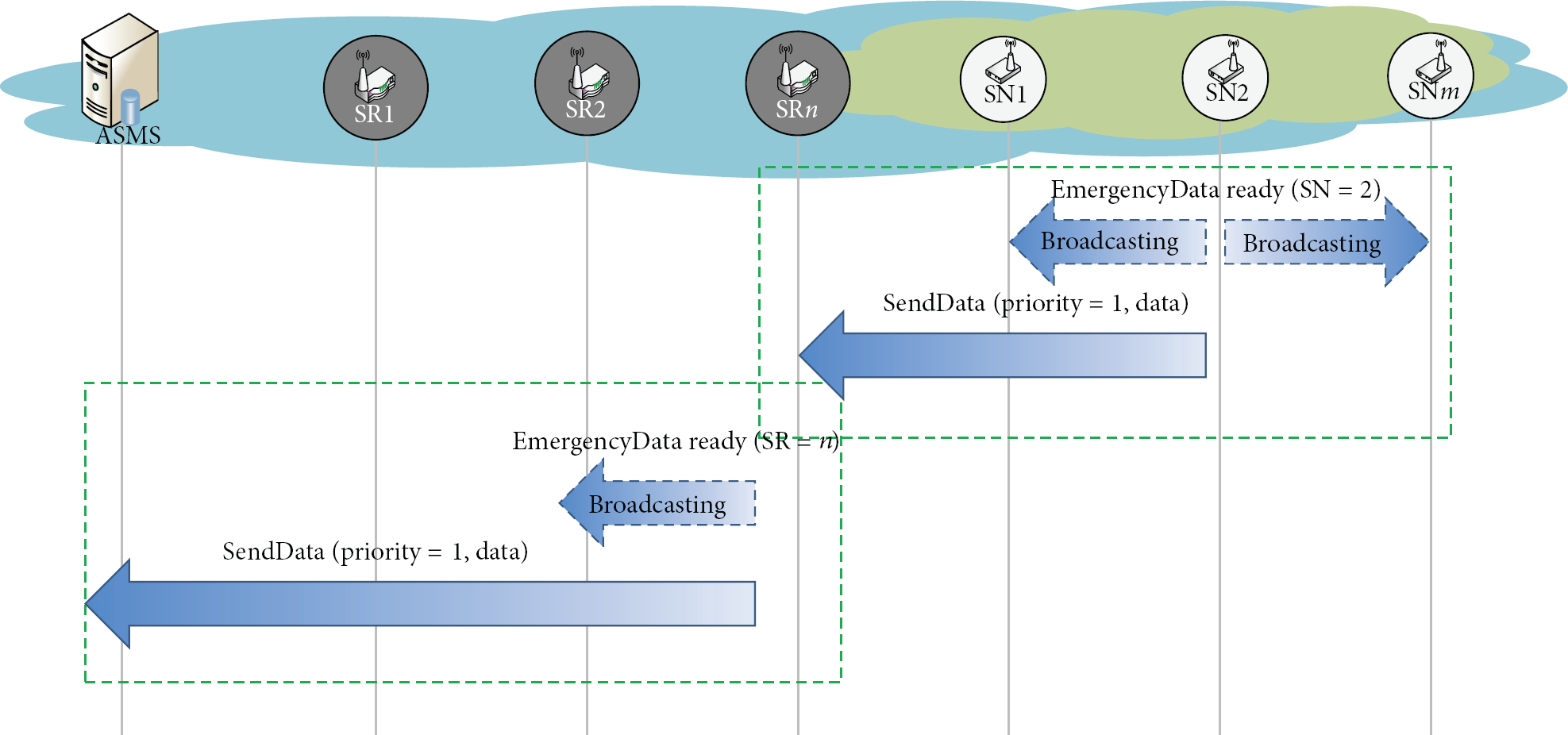
1st priority-based message transmission (upstream).
Figure 9 depicts the method of transmitting a downstream message with the highest priority. The ASMS first floods the network with the EmergencyData_ready message in order to advertise its pending transmission to all the nodes in the upper layer. After flooding, the ASMS transmits the message to the SR. Similar to the ASMS, the SR first advertises its pending transmission to all the nodes in the lower layer using message flooding and then transmits the message to the sensor node, which is the final destination.

1st priority-based message transmission (downstream).
5. Simulation
In this section, we discuss performance evaluations using the most recent version of the ns-2 simulator (i.e., ns-2.35). Figure 10 shows an example of the test topologies. The sink node is located at the center of network, and the sensor routers are placed on the network in a grid pattern. The horizontal and vertical distances between the adjacent sensor routers are identical to each other, and the distance is set to 100 m. The sensor nodes are randomly placed throughout the network. The number of senor nodes is varied from 32 to 1024.

Simulation environment.
We have assumed that no mobile nodes exist. The size of the data packet is set to 64 bytes, and the channel bit rate is set to 250 kbps. Both the transmission and RF interference ranges are set to 50 m. Our proposed scheme is compared with the SMSR protocol over IEEE802.15.4 MAC/PHY. The simulation environments are summarized as in Table 1. The performance metrics of interest for evaluating the effectiveness and efficiency of the proposed scheme are the configuration time, packet delivery ratio, end-to-end packet delay, and priority packet delivery ratio and they are shown in Figures 11–14.
Simulation environments.


Network configuration time.

Packet delivery ratio (upstream).

End-to-end packet delay (downstream).
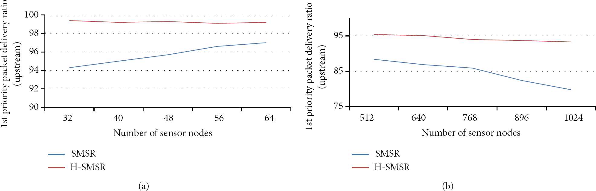
First priority packet delivery ratio (upstream).
Figure 11 shows the network configuration time according to the network scale. The performance gain achieved by the proposed scheme in terms of the configuration time is marginal in a small-scale network. However, our proposed scheme yielded approximately two times shorter configuration time in a large-scale network.
Figures 12 and 13 show the upstream packet delivery ratio and end-to-end downstream packet delay according to the network scale, respectively. The upstream packet delivery ratio of our proposed scheme is higher than that of SMSR. The performance of the end-to-end downstream packet delay is approximately two times less than that of the SMSR in a large-scale network. These results indicate that our proposed scheme can provide more reliable and scalable services.
Figure 14 shows the highest priority upstream packet delivery ratio according to the network scale. Our proposed scheme can successfully deliver the approximately 99% of the highest priority upstream packets to the destination in a small-scale network, and it can deliver greater than 90% of the messages in a large-scale network.
6. Conclusion
In this paper, we proposed an ASCI designed to provide various services efficiently and process large-scale sensor data effectively. In addition, we proposed H-SMSR, which is an extended version of the existing SMSR design and composed of HSR and AGR. Our proposed H-SMSR protocol can decrease the network configuration time, increase the packet delivery ratio, decrease the end-to-end packet delay, and provide reliable transmission of packets with high priority in large-scale WSNs. It is verified from the simulation results that our proposed scheme is more suitable for providing more reliable and scalable service in large-scale WSNs as compared with the existing scheme.
Footnotes
Conflict of Interests
The authors declare that there is no conflict of interests regarding the publication of this paper.
Acknowledgment
This work was supported by the IT R&D program of MSIP/KEIT (10041145, Self-Organizing Software Platform (SoSp) for Welfare Devices).