
Abstract
This paper describes a robotic bone drilling and screwing system for applications in orthopedic surgery. The goal is to realize two robot manipulators performing cooperative bone drilling. The proposed cooperative bone drilling system can be divided into hardware and software development. The hardware development section consists of two robot manipulator arms, which perform drilling and gripping of the bone, and operates using two joysticks. The software section assists the surgeon in visual and navigation control of those robot manipulators. Controller used in this system can be included in the hardware and software sections. Disturbance observer based position control was used in the robot manipulator maneuver and reposition controller (cooperative control) was used in cooperative drilling operation to maintain the alignment of the drill bit during drilling. A mathematical model for the control system was designed and a real environment mimicking simulation for bone drilling was designed. The result of the simulation shows that the cooperative robot system managed to perform cooperative drilling when misalignment occurs during bone drilling. The bone gripping robot managed to restore the drill bit to its ideal alignment in every event of misalignment in the drilling axis. Therefore this cooperative system has potential application in experimental orthopedic surgery.
1. Introduction
Orthopedic drilling is generally performed to extend length, straighten deformities, and remove regions affected by tumors and infections of the bone. Due to the rigidity of the bone and the precision required, orthopedic drilling is one of the focus areas for robot assisted surgery. The main advantages of robot-assisted orthopedic drilling over conventional orthopedic techniques are the improved accuracy and precision in the preparation of bone surfaces, more reliable and reproducible outcomes, and greater spatial accuracy. The ability to isolate the bone and rigidly fix the bone into a known position allows robotic devices to be securely fixed to the bone. As such, the bone is treated as a rigid object, simplifying the computer control of the robotic system. This makes orthopedic drilling ideally suitable for the application of robotic systems. The general goal of robotics system in orthopedic drilling is to improve the accuracy of surgical procedures, minimize the invasive drilling, and provide intelligent systems for training and education. Commercially available robotic systems are classified as passive, semiactive, and active devices [1]. Robot-assisted orthopedic drilling is still very much in its infancy but it has the potential to transform the way orthopedic procedures are going to be performed in the future. Allotta et al. [2] designed a mechatronic drill system for surgical application; the drill is equipped with force measurement sensor to assist the surgeon to detect the breakthrough in long bones. A similar research was conducted by Ong and Bouazza-Marouf [3], which shows the possibility of detecting bone breakthrough without the necessity for extensive X-ray scanning which is considered a threat to the health of surgeons in the long term. In this experiment they have used Kalman filter to detect the breakthrough over wide range of drilling bit types and different drilling conditions. Lee and Shih [4] applied a robotic bone drilling system for orthopedic surgery. Their robotic system consists of 3-axis robot manipulator equipped with a drilling tool and force sensor. The system can stop the drilling when the breakthrough is detected. Robodoc [5, 6], RIO (MAKO Surgical Corp) [7], and Acrobat [8] are examples of commercially available orthopedic drilling assistance systems which are currently being widely tested. The Robodoc uses a CT guidance to drill a precise hole into the femoral cavity in knee replacement. The Acrobat belongs to a class of products known as surgical navigation systems, such that they provide real-time computer assistance in tracking the spatial locations of tools and patient bone. The information is then depicted against the visual information of the preoperative planning that provides guidance to the surgeon during surgery. RIO uses tactile robotic system, which requires surgeon to operate it. This system was used for unicompartmental knee replacement (UKR). The system's algorithm relies entirely on preoperative planning and CT scan was used to create 3D computerized imaging of the patient's knee. RIO and Robodoc show similar operative procedures used during UKR. However, most of those systems mentioned above are single serial arm robot based systems. The use of multiple cooperative robots in orthopedic drilling was not found in those literatures; besides some general surgical cooperative robots were found. Tovar-Arriaga et al. [9] carried out a research on fully sensorized cooperative robotic system for normal surgical interventions (except for bone and brain) consisting of a DLR/KUKA Light Weight Robot III, a FD-CT robot-driven angiographic C-arm, and a navigation camera. The research main focus was on sensor technology due to the system's heavy dependency on the information coming from different sensors. This system uses target visualization (optical localizer) for robot control and patient tracking. Rojas and Peters II [10] conducted a study for a comparative analysis between two coordination schemes across a heterogeneous robot equipped with force sensing. The study revealed that the robotic cooperation increases the time required to complete certain task. The study also revealed that in “push-hold” schemes, industrial robots perform smoother and faster pushing task and compliant robots are better holders. However both of the cooperative systems were not implemented in orthopedic surgery. The presented works show that there is a great trend in research in this field to improve bone fixation procedures for the benefit of surgeons and patients through the employment of robotic systems. The idea to develop cooperative robots for orthopedic drilling assistance (CRODA) was derived by simply analyzing orthopedic surgeon's dual arm surgical implementation during orthopedic surgery. The main advantage and benefit of dual-arm compared to single arm system is multitasking. The arm can operate independently or synchronously performing complex bimanual assembly tasks [11]. The objective of this system is to perform cooperative control in orthopedic bone drilling procedures. The system cooperativeness was established by performing a significant perpendicular bone drilling on the bone surface. One particular robot arm manipulator will perform the bone gripping and another robot arm manipulator will perform the drilling. If there is a change in the drilling direction, the gripping robot arm manipulator will reposition the bone along the required drilling direction. Therefore a cooperative robot for orthopedic drilling assistance (CRODA) was proposed (see Figure 5). In this paper we will discuss mainly about CRODA development in the aspect of hardware and software. The paper is organized as follows. Section 2 gives an overview of the system. In Section III, the cooperative system setup was presented. Section 3 describes the cooperative system controller, while Sections 4 and 5 provide the discussion of the results and further directions.
2. System Overview
The proposed CRODA system is basically for research purpose. This system consists of a 6-DOF robot manipulator (CRSPLUSA456 model) and a 5-DOF robot manipulator (CRSPLUSA255 model). The 6-DOF robot manipulator will perform the drilling task on the bone, whereas the 5-DOF robot manipulator performs the gripping of the bone. Both robot manipulators are equipped with the following setups as shown in Figure 1. Cameras in Figure 1 allow the surgeon to visualize the surgical process on a computer monitor while the surgeon maneuvers the robot manipulators to perform an orthopedic surgery. Robot manipulators are remotely operated using two joysticks as shown in a graphical form in Figure 2. Figures 3 and 4 are user interfaces designed for the surgeon who depends solely on the visualized operation procedure view and the joystick navigation from the control monitor screen. Maneuvering a particular robot manipulator using a joystick requires a perfect match in directions and angles between the joystick and the robot manipulator. This interface consists of mapping algorithm for joystick and robot manipulators motion mapping process which will be explained in the following section. A surgeon will navigate the CRODA system by using two joysticks to maneuver two robot manipulators separately.

The 6-DOF robot manipulator is involved in the drilling of the bone and the 5-DOF robot manipulator is involved in gripping the bone.
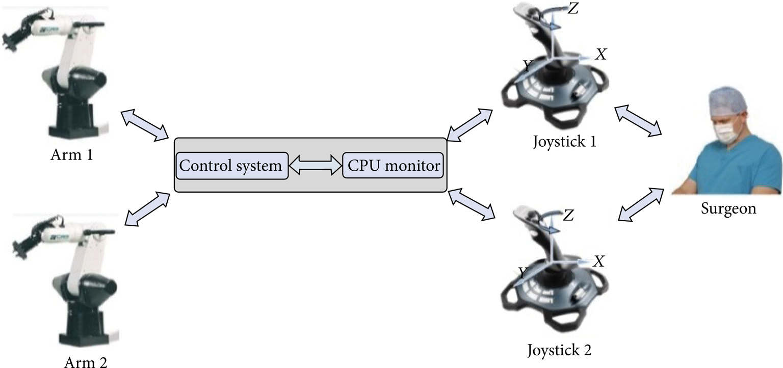
Simple overview on how a surgeon maneuvers both robot manipulators using two joysticks.

Camera 1 and camera 2 view of the robot arm.

Joystick axis view during navigation.
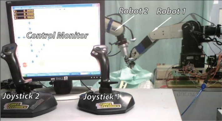
Overall CRODA system setup.
In Figure 3 the surgeon can easily view the real-time bone operation in any locations and the surgeon can even record the surgical scene from the software for other usage.
3. Cooperative System Controller
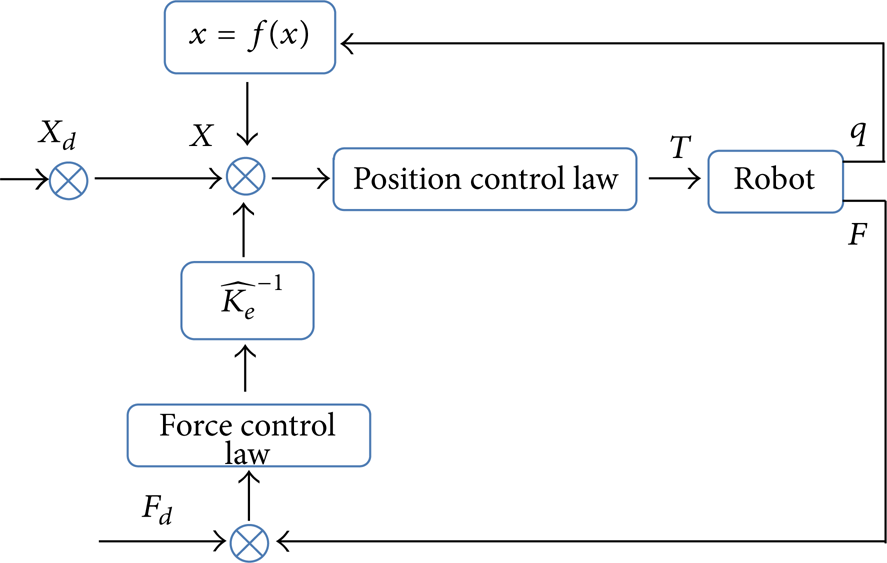
CRODA control system provides position and hybrid (position and force) control in a very unique manner. There are two different sections in the controller where the system automatically chooses the type of control to be executed as shown in Figures 9 and 10. Figure 9 shows that the type of control executed based on the contact force of the drill bit with the bone surface. If there is any contact force between the drill bit and the bone surface, hybrid control will be executed and vice versa. Disturbance observer based position control will be used in major robotic maneuvering such as in Figure 10 where if there is a contact force between the gripper and the bone surface or not, disturbance observer based position control will be executed whereas, in Figure 9, disturbance observer based position control will be used if there is no contact force between the drill bit and the bone surface. Disturbance observer based position control along with hybrid control was designed separately for two robot manipulators (see Figure 6). Only the cooperative controller (reposition control) as shown in Figures 7 and 8 was designed as a single sharing unit due to the cooperative behavior. Force sensor was used to detect driller tip to bone surface contact and also driller alignment during drilling. Threshold dimensions (F x threshold ,F y threshold ,F z threshold ) were obtained through manual measurement and (F x ,F y ,F z ) will be obtained from force sensor feedback in real-time mode. Therefore the proposed controller will make these threshold values as a reference once the drill bit makes contact to the bone surface.

CRODA system controller flow chart for robot 1 (driller).
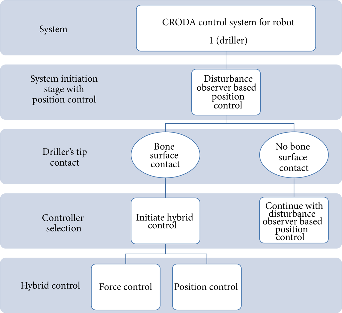
CRODA system controller flow chart for robot 1 (driller).
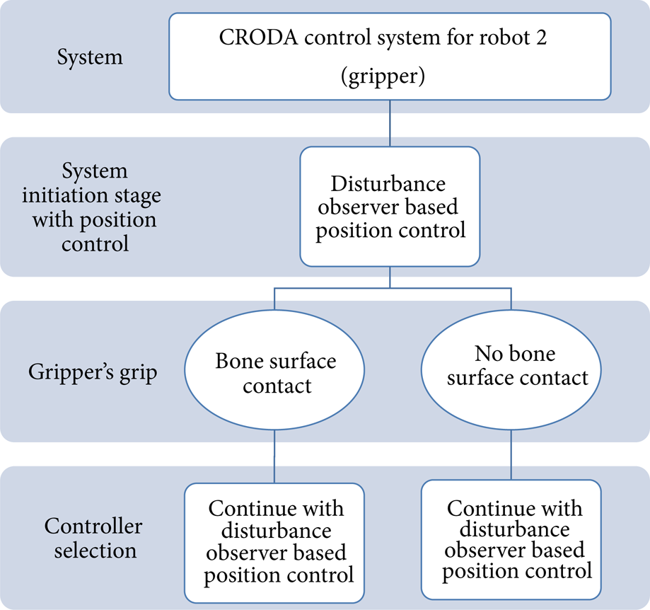
CRODA system controller flow chart for robot 2 (gripper).

CRODA disturbance observer based position control.
CRODA system hybrid controller scheme.
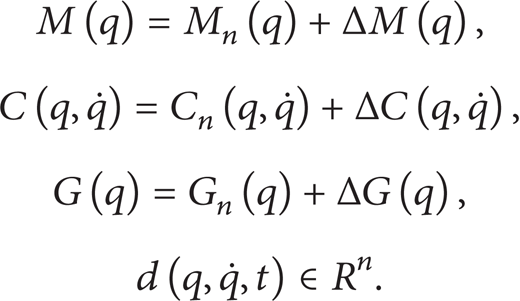
3.1. Dynamic Equation of the Robot Manipulator
The dynamic equation of a robot manipulator in general can be described as

where q∈R
n
is a generalized coordinate, M
n
(q)∈Rn × n is the inertia matrix,

where
3.2. Disturbance Observer Based Position and Hybrid Control
If the parameters of the system are exactly known, the computed torque method would generate a control signal
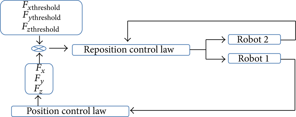
CRODA cooperative control system.
3.3. CRODA Control System
In cooperative system, the system should behave as a surgeon when he/she performs surgical drilling in which both surgeon's hands are at work. In the perspective of manual bone drilling, a surgeon either
tries to maintain the drilling alignment by not moving the bone's orientation,
tries to move the bone's orientation if any drilling misalignment occurs.
This is because, during bone drilling, the orientation of the drill must be perpendicular to the bone surface. Unfortunately manual drilling will not provide accurate sensing to detect the change in the drilling alignment. Therefore this CRODA system and the controller implemented here mimic the above statements. In perfecting a straight drilling through a bone, the force sensors are used to provide force measured during the drilling process. The following equation provides force error:

where F x threshold ,F y threshold , and F z threshold are the alignment thresholds. If F e x>0, F e y>0, and F e z<0, this implies the alignment of the drill bit which has diverted from its original position. The proposed CRODA cooperative control system will insure keeping its original drilling alignment and avoid slipping away from it by performing the following method shown in (5a) to (5c). Driller and gripper robot manipulator control flow is shown in Figure 11 and the system flow is shown in Figures 8, 9, and 10 for further understanding of the control system:


where qadj(x,y) is the adjusted position, qadjAngle(x,y) is the error angle, and qgripper(x,y) is the current angle of the gripper.
4. Simulation and Experimental Results
In this section, the simulation results for CRODA control system are shown. The overall hardware setups have been discussed in detail in the previous sections. Simulations are basically performed for control system development. Therefore, in this section, control system simulation results for disturbance observer based position control from Figure 11 and reposition control based on (4) to (5c) are shown.
Figure 13 is a simulation result from the control model in Figure 12. The “dynamic model” and “observer” block in Figure 12 were constructed based on mathematical explanation in Figure 11. Aq joint i represents the actual angle and Dq joint i represents the desired angle of motion where i is the number of joints. In Figure 12, the “position controller” block has the following gains [Kp1, Kd1], “dynamic rrror” has [Kp2, Kd2], and “observer” has [K1, K2, K3, K4]. Therefore the following are the gain values used [Kp1, Kd1] = [100,1], [Kp2, Kd2] = [100,1], and [K1, K2, K3, K4] = [47.97,7.54, −0.21,0.73]. In Figure 14, graph (a) represents the force measurement for a perfect straight line drilling whereas graphs (b) and (c) represent the force measurement for drilling misalignment that occurs at any axis. The start point represents the initial contact force of the drilling bit with the bone and the end point represents the moment when the drilling bit is not touching the bone. In this simulation result, drilling misalignment occurred at F x force direction. Therefore reposition control system was automatically initiated at approximately 3.73's. As a result to the misalignment, the force measurement along F z direction reduced to approximately 50 Nm whereas the force measurement along F x direction increased approximately 63 Nm. To realign the drill bit to its original F z direction, the gripper robot which grips the bone needs to move to a certain angle to restore a straight drilling along the F z direction. At approximately 4.77's the drill alignment was restored.

Disturbance observer based position control model.

Disturbance observer based position control simulation result.
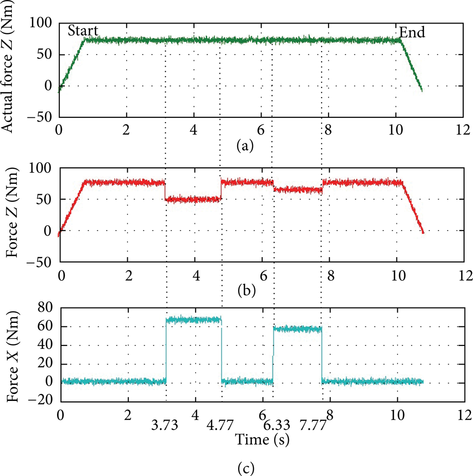
Reposition control system during drilling.
In the experimental method, a gamma sensor as shown in Figure 15 was used. This sensor has the capability to provide 6-axis force/torque measurements (
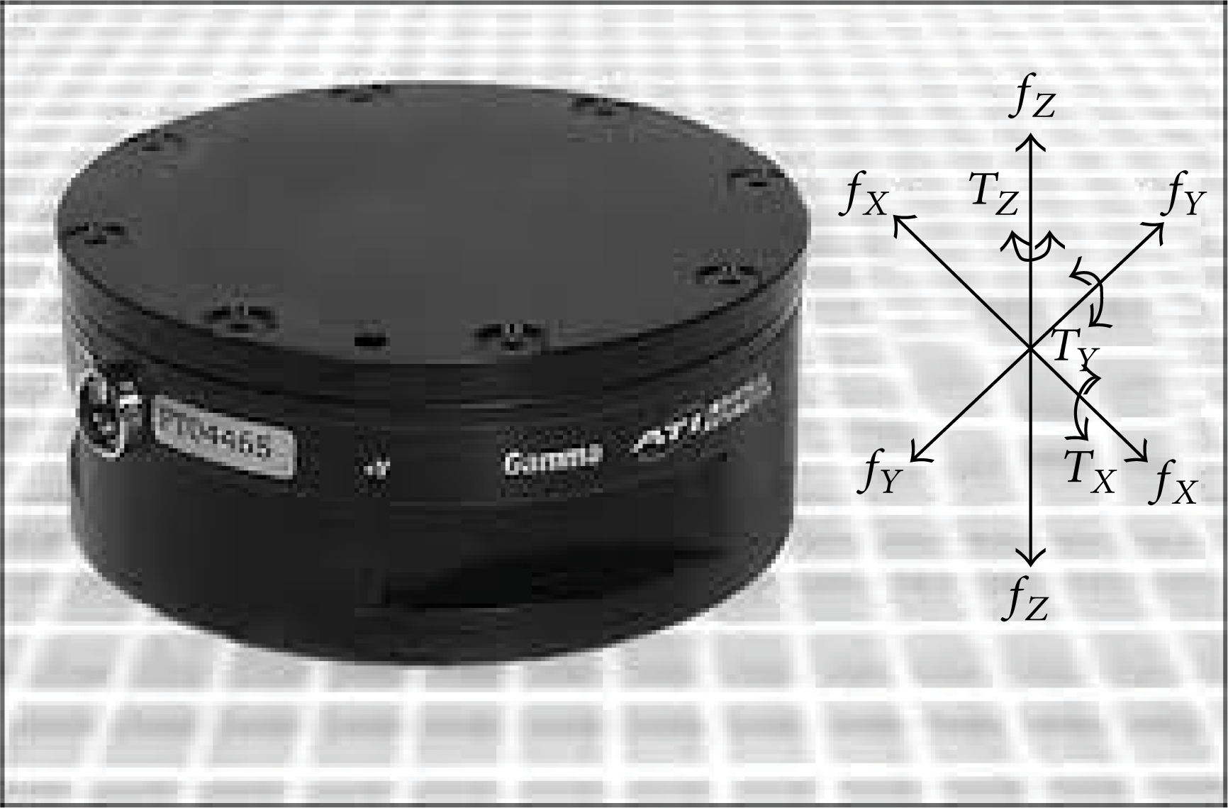
ATI 6-axis force/torque sensor.
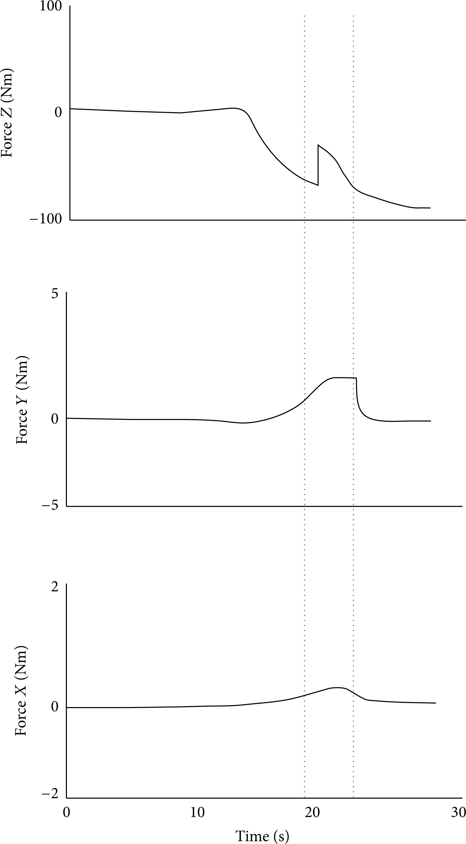
Force acting on the drilling tip during actual bone drilling.
5. Conclusions
This paper proposes a general framework for design and development of cooperative robot for orthopedic surgical assistance along with controllers for nonlinear systems under disturbances cooperative control. There were few cooperative robot systems but none of them were developed for orthopedic surgery. In this paper a cooperative robot was developed to assist in bone drilling and screwing. This system can also be used for bone cutting. This system is semiautomated, where a surgeon's attention is required especially during initial navigation of the system.
Once a contact was made between drilling bit and the bone surface, the automated system will be initiated in the aspect of alignment drilling (straight drilling). The cooperative aspect is only established during the drilling process. It is shown that this approach is quite flexible and can be integrated with experimental evaluation.
Conflict of Interests
The authors declare that there is no conflict of interests regarding the publication of this paper.
Footnotes
Acknowledgments
Special thanks go to the Ministry of Higher Education, Malaysia, for financial support given to this project. Grant by High Impact Research (HIR), University of Malaya, under Project no. UM.C/HIR/MOHE/ENG/41 and providing financial support under the Research Grant “Program Rakan Penyelidikan UM” (Grant no. CG036-2013) by University of Malaya are acknowledged.