
Abstract
A newly designed marine diesel engine piston was modeled using a precise finite element analysis (FEA). The high cycle fatigue (HCF) safety factor prediction procedure designed in this study incorporated lubrication, thermal, and structure analysis. The piston ring dynamics calculation determined the predicted thickness of lubrication oil film. The film thickness influenced the calculated magnitude of the heat transfer coefficient (HTC) used in the thermal loads analysis. Moreover, the gas pressure of ring lands and ring grooves used in mechanical analysis is predicted based on the piston ring dynamics model.
1. Introduction
The increasing demand for high power density, low emission, and low fuel consumption engines impose many restrictions on the design of diesel engine components. The piston is one of the most challenging components in diesel engine design. Pistons are subjected to high thermal and mechanical loads. Large temperature difference between piston crowns and cooling galleries induce significant thermal loads. In addition, gas pressure and piston acceleration can develop cyclic mechanical stresses which are superimposed on earlier thermal stressed components. This cycle of thermal and mechanical stresses causes the thermomechanical fatigue that is the main cause of failure in diesel engine pistons.
In this study, the authors focus on damage caused by fatigue. This damage is created both by thermal and mechanical stresses [1]. To improve the life and reliability of pistons, a large number of fatigue tests are carried out when designing new pistons [2–4]. However, to reduce the cost and time involved in fatigue testing, many engine manufactures use FEA to predict the distribution of temperature and stress on engine components. The fast development of the numerical calculating technology has allowed FEA to become a significant tool in mechanical dynamics analysis, thermal analysis, and thermomechanical coupling analysis of new piston designs [5–8] and in thermomechanical fatigue analysis [9]. Under thermomechanical fatigue loading, piston failure may occur due to fatigue, material degradation due to environmental influence (oxidation), and creep mechanisms [10]. Thermomechanical fatigue life assessment methods can be classified as empirical methods, fracture mechanics theories, continuum mechanical models, and models based on microstructure [11]. Empirical models correlate the number of cycles to failure to parameters of the hysteresis loop, for example, stress, strain, and plastic strain [12].
In this study, a three-dimensional FEA is used to predict the thermomechanical behavior of a newly designed diesel marine engine piston. In order to accurately determine the heat transfer coefficient (HTC) of the piston head, the oil film is taken into consideration in the thermal analysis. The thicknesses of oil film between ring/piston and ring/bore are determined using a ring pack lubrication model. To calculate the oil pressure distribution in the piston lands/grooves operation, a piston ring dynamics model is used in the mechanical loads analysis. The coupled actions of thermal loads and mechanical loads (including combustion pressure, inertial load, and oil pressure in ring lands/grooves) are used to predict fatigue life. The prediction procedure designed in this study is the combination of lubrication analysis and structure analysis. The results obtained by this new method will provide a guideline for further optimizing piston design.
2. The Finite Element Model
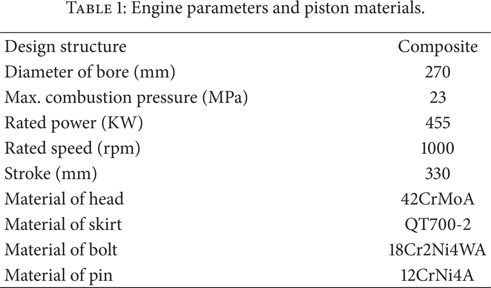
Due to the symmetrical structure of the piston, a 1/4 3D solid model (Figure 1(a)) including piston, pin, and rod was created. The FE software ANSYS was used for FEA in this study. For the FE model, 3D 8-node solid elements solid45 was chosen to perform the thermomechanical coupled analysis. As shown in Figure 1(b), 37246 nodes and 60638 elements were obtained. The materials of each part are listed in Table 1. Since this study focuses on the piston properties, the connection rod is set as a rigid body for analysis.
Engine parameters and piston materials.

The solid and FE model of the piston.
The surface-surface contact unit is placed on the contact surface between the piston pin hole and the piston pin, head and skirt, head and bolt, skirt and bolt, pin and bush, pin and skirt, and bush and rod. Figure 2 shows the contact pairs in this piston model.

The contact pairs distribution in the piston model.
3. Theory
3.1. Thermal Boundary Conditions
Piston temperature is usually considered to be independent of the operating states and remains constant during a working cycle [13]. Since the time response of piston material to the variation of boundary conditions in a firing cycle is very slow, a steady state thermal analysis has been done considering the typical values of temperatures and heat transfer coefficients at piston boundary surfaces during one firing cycle. Based on the third kind of steady-state heat conduction, conductive heat transfer boundary condition is that the temperature of the fluid medium contacting to the objects and the heat transfer coefficient are known, and can be shown as
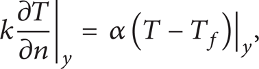
where T f is the medium temperature, α is the HTC, and T f can be constant or time and position variety, as well as α [14].
(1) HTC on Piston Top Surface. Based on the assumption of a steady working state of the engine, the average HTC and the average piston surface temperature in a whole working cycle can be given as
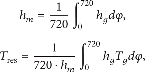
where hg, T g are the instant HTC of gas at piston surface and instant gas temperature. According to the design parameters of the engine, hg and T g can be calculated by GT-Power (Figure 3). According to (2), h m = 1214.88 W/m2 K and Tres = 913.31 K.

hg, T g calculated by GT-Power.
Using Seal's formula and experimental data, the HTC of piston head is the function of position in radial direction:

where r is the distance from a local point to the center axis of the piston head and N is the distance from the point where the maximum temperature occurs to the center axis of the piston. For FEA modeling, the top surface of the piston is divided into 10 subregions radially. Then, based on the piston's structural parameters, the HTC on the top of head can be determined by (3). The HTC distribution of the top head of the newly designed piston is shown in Figure 4.

HTCs distribution at the top of piston head.
(2) HTC at Skirt and Cooling Oil Channels. The current analysis used HTC values at the skirt and oil channels that were determined by Lu et al. [14]. Their analysis used a piston with a similar structure and size.
(3) HTCs at Piston Ring Lands/Groove. The thermal transfer process in piston ring lands/grooves is shown in Figure 5. Figure 5(a) is the thermal resistance map from piston to bore through ring land, and Figure 5(b) is the thermal resistance map from piston to bore through ring groove. The resistances in the transfer paths (Figure 5) have been specific by Lu et al. [15]. Parameters such as the position of ring during operation and the thickness of oil film between ring/bore and ring/piston are important in the heat transfer process. In order to predict the magnitude of those parameters, a ring dynamics analysis is applied in this study.
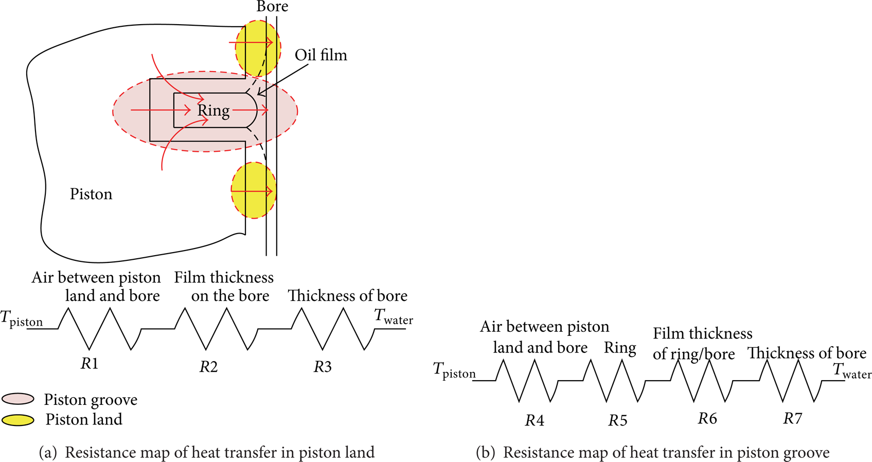
The resistance map of heat transfer from piston head to bore.
(4) Ring Dynamics. The motion of piston ring within the piston groove can be described by the axial rotational (torsional twist) and radial motions in the three respective degrees of freedom. The ring motion in the circumference direction is neglected in this study. A small section of the ring at a circumferential location is considered in the analysis (Figure 6). The whole ring dynamic analysis model developed by Tian et al. [16] is used in this study. Considering the complexity of heat transfer and time consumption of simulation, the section of thrust side (TS) is used. The governing equations for the ring motion are

where ycg and hcg are the axial and radial position of the center of gravity of the ring and α is the twist angle. mr, I
r
, and K
rt
are ring mass, moment of inertia for toroidal rotation, and cross-sectional torsional stiffness. K
rr
is the radial tension stiffness, h′ is the reduction in ring radius at installation, and h0 is the minimum ring-bore oil film thickness (

For a complete ring with rectangular cross section, the cross-sectional torsional stiffness (K rt ) is given by

where E is the modulus of elasticity of piston ring, b is the axial height of piston ring section, d is the inner diameter, and D is the outer diameter of piston ring. The axial motion of a ring relative to piston can be expressed as
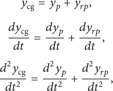
where yp is the axial position of the piston and y rp is the axial position of the ring related to the piston. And yp can be given out by the piston secondary motion together with the axial motion. Using a developed version of an existing ring pack lubrication model, Gamble et al. [17] investigated the effect of piston secondary motion on the performance of a diesel engine piston ring pack, in terms of gas flow and interring gas pressures. For an example engine operating condition, the effect of secondary motion on the ring pack was calculated for a number of ring gap positional combinations. The secondary motion and the positions of the ring gaps were shown to have an effect on the ring pack operating conditions, such as oil film thickness, friction, wear, oil transport, and degradation. And in order to determine the parameter yp, the tilt of piston and axial position are needed, and those two parameters can be calculated by iteration algorithm used in [17].
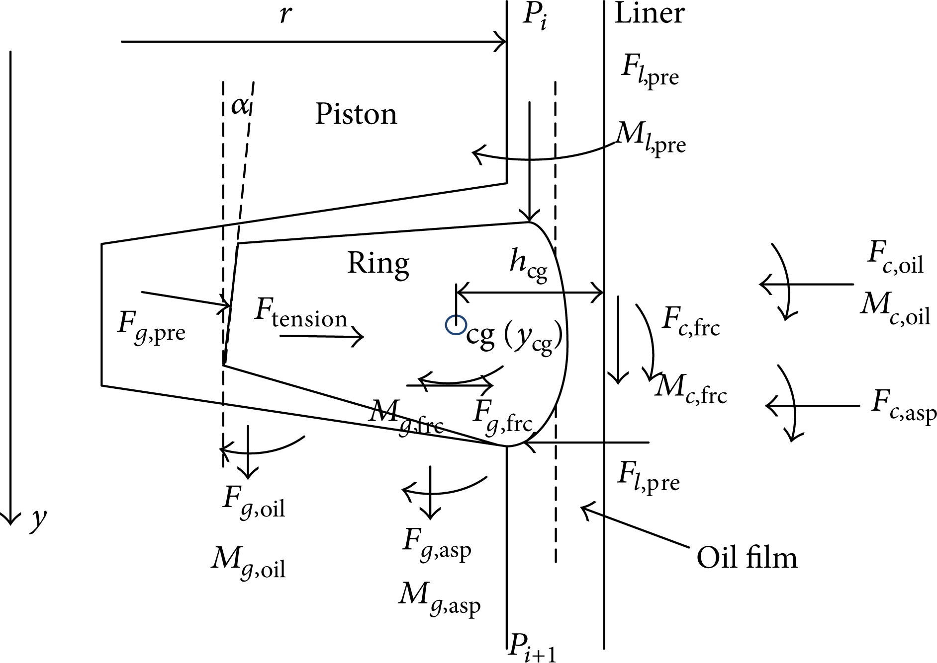
Free body diagram of ring cross section.
Forces and moment associated with land and groove gas pressure are calculated using pressure solutions from the gas dynamics submodel. Forces and moments associated with oil pressure are obtained from the lubrication submodel, and those associated with local asperity contact pressure are calculated by asperity deformation model. Ring axial position and twist influence gas flow paths and the forces at the ring-groove interface. Ring twist also affects the effective profile presented by the ring face to the cylinder bore and thus affects oil film thickness and ring friction. The lubrication model, asperity deformation model, and oil film squeezing model at ring side and groove interface have been previously described [16, 18].
The structure of the rings used in the piston is shown in Figure 7. Each ring is modeled as a single mass; twisting (including pretwist angles) is considered. The equations of motion, which considers equilibrium condition of moments and forces for each ring, are solved. The dynamic components of ring motion are calculated using time integration methods. The cylinder liner typically shows a deformation along cylinder length axis and along cylinder circumference due to bolting prestress and thermal load in the real condition. In this study, the deformation of bore in different cases has been given by Figure 8. The mechanism of piston ring sealing is equivalent to a labyrinth seal, where the gap clearances are determined by the position of the rings in the groove considering the global movement and tilting of the piston [17]. The Reynolds equations are solved iteratively in each time step to determine the hydrodynamic pressure distribution between ring running surface and liner. All relevant mechanisms are considered; the calculation is done quasi-statically per time step. The tilting angle of piston is given by Figure 9. And the motion of each ring in groove during operation is shown in Figure 10 and the thickness of film oil between each ring face and bore is shown in Figure 11.

The geometry of the piston rings.

The bore deformation.
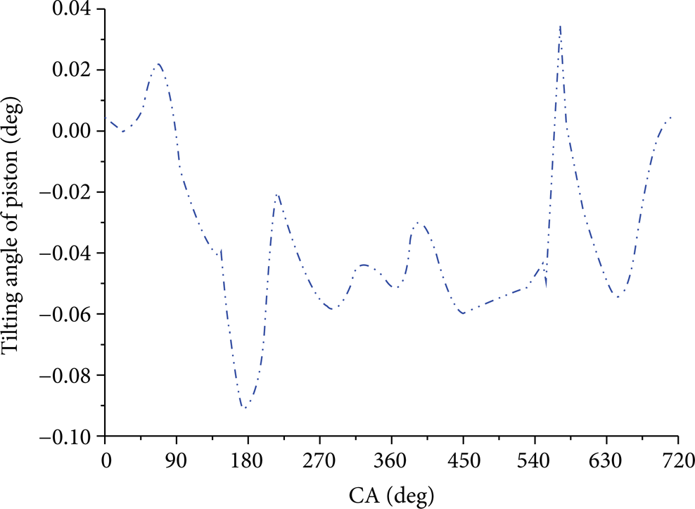
The tilting angle of piston during operation.

The position of rings in groove.

The film thickness of each ring.
3.2. Temperature Distribution
Using the mathematical model developed above, the HTCs distribution in piston grooves/lands can be determined after getting the position of each ring and the film thickness between each ring and bore. Based on the determined HTCs in the top head, piston lands/grooves, and piston skirt, the temperature distribution of the piston is predicted by FEA in ANSYS (Figures 12 and 13). As shown in Figures 12 and 13, the temperature intensity distribution decreases gradually from the head of the piston to the bottom of the skirt. A maximum temperature of approximately 392°C is obtained on the head of the piston at the combustion chamber chamfer edge (Figure 12). This result is similar to that obtained on a similar type of piston in an earlier study [19]. The temperature decreases radically towards the outside and inside of piston. The temperature is 156°C and 134°C at the bottom of fire land and second land, respectively. As it is shown in Figure 11, the temperature distribution in the skirt, bolt, and pin are lower than the piston. The maximum temperature is 155.6°C, 250°C, and 99.7°C, respectively.

The temperature distribution of piston head.

The temperature distribution of piston skirt, connect bolt, and piston pin.
3.3. The Mechanical Loads
The working piston not only bears a thermal load, but also the high pressure of the fuel gas and the inertia force created by the reciprocating motion. The most strenuous condition of running the piston is the moment when the pressure in the combustion chamber reaches its maximum value. Therefore, this study lays emphasis on the stable stress at the combustion moment when operating at a stable speed.
(1) Gas Pressure. Gas pressure is primary loaded on the top of head. However, the piston lands and grooves are also loaded. The gas pressure in the chamber is calculated from GT-POWER based on the design parameters of the new piston. The pressure acts on ring lands and grooves are calculated using a piston ring dynamics program. Based on the ring dynamics model developed above, the gas pressure in lands and grooves are calculated (Figure 14).

The pressure in lands and grooves versus crank angle.
(2) Reciprocating Inertial Force. Due to the reciprocating motion of piston in the cylinder, the inertial force of the piston cannot be ignored in the mechanical analysis. Based on the engine dynamics, the reciprocating inertial force P j is related to the acceleration of the piston. The force action line is parallel to the center line of the cylinder. Because the inertial force direction is opposite to the acceleration, the effect of gas pressure on piston might be subducted. The reciprocating inertial force is calculated as
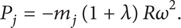
The acceleration at the moment of combustion is given as

where ω is the angular velocity, ω = nπ/30, n is the rotational speed, rpm, and λ is the ratio of crank radius R and rod length L.
3.4. Thermomechanical Fatigue Life Prediction
The high cycle fatigue prediction is based on the thermomechanical analysis results of alternating conditions. The first condition is the moment when the piston is at the top dead point after outbreak and the alternate condition is when the piston is at the bottom dead point in the exhaust stroke. The Haigh diagram is modified according to the magnitude of the stress gradient, nodal temperature, and modification factors at each node. The mean and alternating stresses resulting from the alternating conditions are computed at each node; then, the HCF safety factor for each node is attained.
The selection of the displacement boundary condition significantly affects the finite element analysis. A symmetrical restraint is applied on the symmetry plane because a quarter of a symmetric piston is modeled. Three degrees of freedom on the bottom of the rod of the piston assembly are restrained to hold the piston in a static condition.
In this analysis, a multilinear kinematic hardening model is used to account for material nonlinearity. The following load cases are defined to simulate different stages of the work cycle:
application of the pretension force of the bolt to the model;
application of thermal loads (temperature) to the model;
application of inertia loads (piston acceleration) to the model;
application of maximum pressure of combustion gases to the top head, the lands pressures, and grooves pressures to the model.
4. Results and Analysis
The distribution of equivalent von Mises stresses in the piston head after application of thermal loads, inertia loads, pressure of combustion gases, and ring region pressure is shown in Figure 15. In the cooling oil chamber closed to the first groove, the induced stresses are high, 330 MPa, due to the reduction of piston wall thickness and stress concentration effect. Figure 16 shows the distribution of equivalent von Mises stresses in the piston skirt. The areas around the contact regions of piston skirt and piston pin are subjected to severe stresses, 450 MPa (Figure 16).

The von Mises stresses in piston head.

The von Mises stresses in piston head.
The commercial software FE-SAFE is used to calculate the HCF safety factors. The contour of the HCF safety factors in the piston head and pin is shown in Figure 17. The safety factors in the piston head and pin are more than 1.8. This indicates that the design of those components can meet the life limitation. Variable tensile and compressive mean stresses are observed in different regions of the piston skirt (Figure 18). The maximum compressive mean stresses due to mechanical loads are observed in the piston pin hole (114 MPa). The maximum tensile stresses are located on the contact face between connection bolt and skirt (145 MPa). The safety factors at the inner contact areas of pin-pin hole and bolt-skirt are lower than other regions (Figure 19); the minimum value is just 1.02 which does not reach the strength requirement of 1.5.

The safety factor distribution in head and pin.

The mean stresses distribution in piston skirt.

The safety factor distribution in piston skirt.
5. Conclusions
This study performs a detailed thermomechanical stress analysis on a diesel engine piston. Temperature distribution is determined from thermal analysis. In order to calculate the HCF safety factor, the commerce software FE-SAFE is used. A piston ring dynamics calculation is used to determine the thickness of lubrication oil film when calculating the magnitude of the heat transfer coefficient (HTC) in thermal loads analysis. The gas pressure of ring lands and ring grooves in mechanical analysis is calculated using a piston ring dynamics model. The prediction procedure designed in this study is the combination of lubrication, thermal, and structure analysis. The results obtained using this new method provide a guideline for further optimizing the design and manufacture of new pistons. Future work will focus on experimental validation.
Conflict of Interests
The authors declare that there is no conflict of interests regarding the publication of this paper.
Footnotes
Acknowledgments
The present research has been funded by the National Natural Science Foundation of China (Grant no. 51375104) and the Fundamental Research Funds for the Central Universities (Code HEUCFZ1117); the authors would like to sincerely express their appreciation. And the authors greatly thank Melanie Koleini in Washington University for her assistance in checking and refining the language.