
Abstract
We propose a set of distributed algorithms for improving the multicast throughput in wireless sensor networks. To this end, network coding is applied when exploiting path diversity with two disjoint paths to each multicast group receiver. We depart from the traditional wisdom that the multicast topology from source to receivers needs to be a tree and propose a novel and distributed algorithm to construct a 2-redundant multicast graph (a directed acyclic graph) as the multicast topology, on which network coding is applied. We conduct both analytical and simulation-based studies to evaluate the effectiveness and performance of our algorithm.
1. Introduction
Multicast mechanism is mainly used in sink nodes to send control messages to the sensor nodes in wireless sensor networks (WSNs), or in a sensor node to send data to multiple sink nodes. Multicast routing algorithm plays a vital role in WSN regarding the survival time and transmission efficiency of the WSNs.
Ahlswede et al. proposed network coding [1–3] in 2000. This method is useful for greatly improving the network throughput and reliability. Literatures [4, 5] have proved that in each multicast diagram, corresponding linear coding can be found to achieve minimum cut-maximum flow. Zhu et al. [6] found that the network coding has good performance and advantage in multicast network, but the network topology has different effect on the throughput and bandwidth of multicast; redundant multicast figure presented better efficiency and performance than the traditional multicast tree.
Jiang et al. [7] proposed a multicast tree algorithm through network coding, determined the relationship between cluster heads, and analyzed the algorithm performance using network calculus. Yuan et al. [8] analyzed the performance of network coding by the stochastic process. Li et al. [9] analyzed the end-to-end route delay performance based on the network coding using network calculus.
According to the WSN characteristic, considering the geographic and energy-aware routing (GEAR) [10], we constructed k-redundant multicast graph in the form of overlay network in this paper using the multicast algorithm based on network coding (MABNC). We improved the multicast performance by reducing the energy consumption.
2. Algorithm Description
The proposed algorithm is for sensor networks. Based on the geographic routing algorithms, k-redundant multicast graph was constructed. The network throughput and bandwidth utilization were improved, the effect of minimum cut to maximum flow was determined, and the network multicast routing performance was enhanced by utilizing the network coding mechanism.
Definition 1.
Redundancy multicast figure: redundancy multicast figure is a directed acyclic graph with a single multicast source node and has the following two properties.
Figure 1 shows that among the WSN nodes, the gathering and sensor nodes formed wireless sensor multiple hops self-organizing network through hierarchical forwarding and were connected; the first layer comprises the gathering node, the second layer comprises the cluster head node, and the third and fourth layers comprise the common sensor nodes. Figure 1 can be further decomposed into k-redundant multicast figure. Figure 2 shows that the gathering node can be the multicast source node s, the second and third layer nodes can be the multicast transit nodes, and the ordinary sensor nodes can be the receiving nodes. In this paper,

WSN topology.
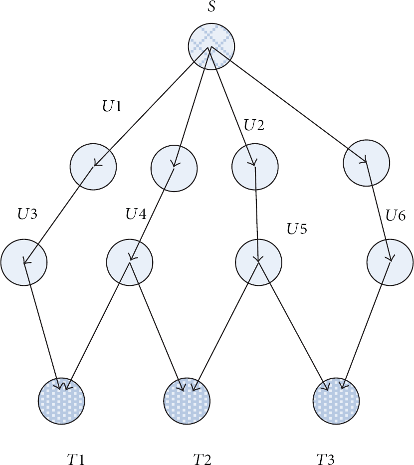
2-redundant network diagram.
2.1. Building and Maintaining k-Redundant Multicast Figure
Building k-redundant multicast figure needs to satisfy the following conditions to ensure the performance of multicast routing:
ensure minimum energy consumption;
build k-redundant multicast path from the source node s to the receiving node t;
guarantee the minimum amount of transit nodes built from the source node to all of the receiving nodes;
maintain the least link load stressed to ensure the minimum times being forwarded on the same physical link of the same packet.
The whole process can be divided into three steps as follows:
2.1.1. Building Preliminary Figure
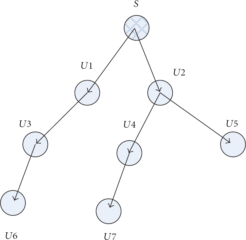
In building a preliminary figure, when a new node joins a preliminary diagram, GEAR mechanism is used. The nearest preliminary node will be chosen to lead the joining of preliminary to be transshipment node and form the preliminary figure of each node, as shown in Figure 3(a).

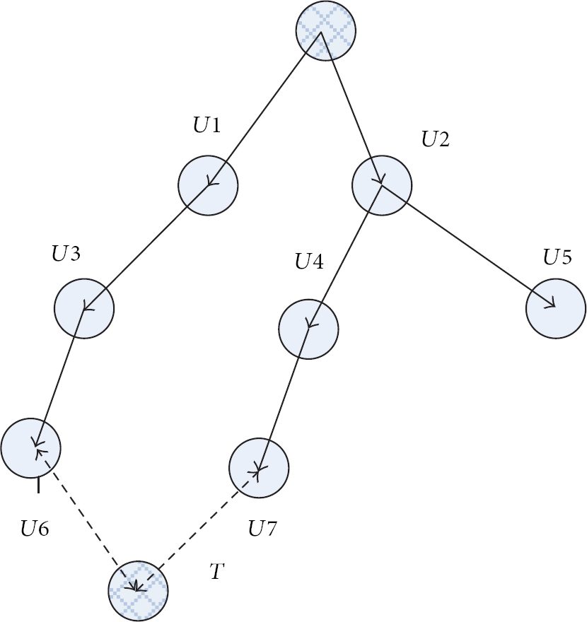
Conversion of the origin figure to 2-redundant multicast figure.
2.1.2. Building k-Redundant Multicast Figure
Figure 3 shows that for each receiving node, two unmutual crossed best route paths need to be established from the source node in a preliminary figure. The pros and cons of a path are mainly evaluated through a tree tuple.
Definition 2.
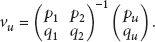
Path evaluation: the quality of the link from the source node s to the receiving node t must be evaluated. If the link quality is a triple, the edge of the preliminary figure (or the link between two nodes i, j) is set to e; that is,

where α, β, and λ are the normalized parameters,

In Formula (2), the minimum
In WSNs, as the sensor nodes join or quit dynamically, the network topology changes. The preliminary figure also changes. The path quality evaluation and calibration can be performed periodically. When a better path occurs, the existing path must be replaced with the better path to guarantee at least two or more unmutual crossed best route paths from the receiving node t to the source node s.
To transform the distributed graph into 2-redundant multicast figure, according to the definition requirements of 2-redundant multicast figure, the following requirements must be satisfied.
In multicast figure, the degrees (i.e., the sum of indegree and outdegree) of all nodes, including the source node s, the transmitted node u, and the receiving node t, should not be greater than
The source node s should has k child node, and
If the child node of the transfer u is the receiving node t, then the transfer u child node's number is not greater than
The fourth rule is used to ensure that at least one outdegree's value of the transit nodes is vacant for adding new transit nodes and for realizing the extensibility and scalability of the multicast figure. When adding a new receiving node to the multicast figure, we can determine the new transit node rapidly to receive the join requests and improve the search speed of convergence.
2.1.3. Receiving Node to Join
Given the low energy of node and the complex network environment of WSNs, the node failure or sleep scheduling causes rapid changes in the network topology. Therefore, the flexible mechanism of the receiving node is needed to join.
The node that can receive the joining node is defined as the transiting node of leave.
Definition 3.
The transiting node of leave denotes that its child nodes are not the leave nodes in the multicast figure. As shown in Figure 4,
Tree consisting the transiting node.
Definition 4.
Saturated node: in the transiting node of leave, if the degree is
The receiving node t to join the process of multicast is also added to the tree that consists of the transfer nodes in Figure 4. The process can be divided into two steps as follows:
Figure 5 shows the joining of the node T in the multicast diagram. The node T determines first whether a node of multicast diagram exists in the neighbor nodes. The following three situations exist.
Two or more than two nodes exist. According to the function of the link quality evaluation in Formula (1), two nodes are chosen from many eligible nodes and the request of access is initiated. The node T has two neighbor nodes (i.e.,
If only one node exists, links to join and begins flooding search until another multicast diagram node is found.
Requests are flooded until two multicast diagram nodes are found if the neighbor node does not exist in the multicast diagram nodes.
Node to join.
Two mutually cross paths (
The receiving node t: From the neighbor node of tor by flooding, find k unsaturated nodes (1) Send paths to (2) Request the unsaturated node paths (3) where Find best path() is as follows: The link quality evaluation of query nodes every unsaturated node Calculate Choose the best path to return; The transiting node Receive the requests of the best path If Send If
The receiving node t: If the neighbor node of t is an unsaturated node u = Find best path If the neighbor nodes of T are all saturated nodes, Search the whole multicast tree until an unsaturated node is found, u = Find best path Find best path() is defined as follows: Find best path The link quality evaluation of query nodes is for every unsaturated node calculate Choose the best path to return.
2.2. k-Redundant MABNC
We established k redundant multicast diagram with a special topology based on the above work. The basic characteristic is that every receiving node has k paths. According to this characteristic, we designed a distributed networking coding mechanism to optimize the performance of the wireless sensor multicast. The maximum multicast traffic can be obtained under the same conditions.
In network coding, each transiting node assigns the appropriate coding vector according to certain rules to encode the forwarding data. The receiving node decodes the original data when it collects enough data and coding vector. Data are then received. The core key of this process is to distribute suitable coding vectors to each relay node.
In the tree of k-redundant multicast diagram, for example, 2-redundant multicast, each receiving node has two mutually crossed paths to the source node s. The source node s sends the data a and b in parallel at the same time. The encoding is mainly conducted on the relay node

The encoding vectors satisfy the following rules:
(

The core problem in the whole process is that how to make the relay node assigns the appropriate coding vector. The relay node is divided into the following two classes for processing:
the relay nodes of indegree 1: as codes are not needed currently, the code vectors must be assigned;
the relay nodes of indegree 2: the encoding vector is
The distribution of transiting node coding vector is divided into two stages, namely, the distribution and diffusion phases. Generated by the source node s, the corresponding distribution vector is assigned to each relay node. According to Algorithm 3, the source node s distributes the network coding vector to each node in the multicast diagram. The relay node has two indegrees that respond to the request and only one indegree that does not respond to the request. Assuming that a node responds to the request, the node s generates
Send If Indegree Contact the child node c of the source node s, and the subtree of c contained then searching in the subtree of c. Return the path
Source node S: Broadcast to each relay node of multicast diagram to distribute coding vector; set T = (largest RTT) × 2; set timer t = 0, initialize m = 0; while ( Receive node addr [m] = address of u; Obtain for send node addr [m]; Receive the distribution code of the transit node u; If indegree Do nothing If indegree send message Wait to receive Set
Algorithm 4
node u of indegree 1: when receiving the coding vector
node u of indegree 2: the node u is already at the distribution stage

Source node S: S has produced For send The node of indegree 1 is as follows: Receive Set The node of in-degree 2 is as follows: Receive the coding vectors Set
The node u is sent to its degree of edge data as follows:

The comprehensive Formulas (5) and (6) can be obtained as follows:
In the above process, the relay node u distributes the appropriate coding vector. According to the above analysis, the receiving node t can be decoded to obtain
Theorem 5.
In the 2-redundant multicast tree, after coding and forwarding by the middle node, the receiving node t can encode to obtain
Proof.
Two mutually disjoint paths
This assumption can be verified using Formulas (5) and (6). If Formulas (5) and (6) were established,
3. Performance Analysis
3.1. k-Redundant Multicast Algorithm Complexity Analysis
The entire network node number is assumed as n from the preliminary figure to construct multicast tree. The main work is to build a tree diagram, of which the whole process is similar to the Bellman-Ford algorithm. The complexity is expressed as (
The main task of the receiving node joining is to find neighbor nodes. The number of control message is about
3.2. Network Coding Complexity Analysis
By distributing phase in the entire coding vector, the initialization of message transmission is the broadcasting of multicast tree. The number of packets is O(n). A total of m messages are in response. The message number is O(m). The diffusing phase of coding vector is to spread from each relay node to the child nodes. The number of packets is 2n, so that the overall number of message is O(n).
In the aspect of time delay, the maximum delay from the source node s to the receiving node is T. The source node s in the coding vector distribution stages sets the timing to 2T and initializes the broadcast message for T; thus, the overall worst case is 3T. During the diffusion stage, t is assumed as any two nodes’ maximum delay in the multicast figure. As the distributed algorithm is used, the extension of coding vector is generally not greater than t. Accordingly, the overall coding time delay is O(T).
3.3. Simulation Analysis
3.3.1. Simulation Illustration
To evaluate and analyze the performance of multicast, the NS platform is used for simulation. The experimental environment is as follows: 500 sensor nodes are distributed to 100 m by 100 m square area randomly; the receiving node is 100, and the gathering node is in the network center. The signal collision and the influence of random factors, such as wireless channel interference, are ignored. The other important parameters used in the experiment are shown in Table 1. The topology of the network simulation is shown in Figure 6.
Simulation parameters.

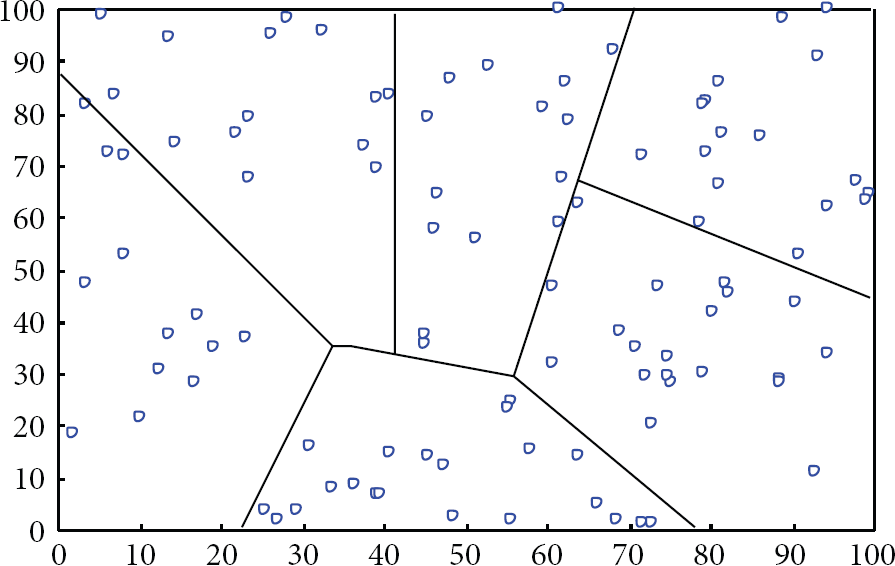
Topology of network simulation.
3.3.2. Simulation Analysis
The comparative analyses of several aspects, such as the average energy consumption of nodes, end-to-end delay, and packet loss rate, with the traditional multicast mechanism based on tree and the tree multicast mechanism based on network coding are conducted.
( 1) Average Energy Consumption of Nodes. The node energy consumption is that in WSNs, the average energy consumption in the node running is computed as follows:

where n is the number of sensor nodes. As shown in Figure 7, the whole simulation ran for 256 s. The first 120 s is for the building of multicast topology. At this time, the energy consumption is more in the three algorithms. The following 136 s is for the data's multicast process. Based on the simulation curve, the computational cost of the MABNC algorithm of multicast figure based on network coding increased compared with the traditional multicast mechanism based on tree and tree multicast routing algorithms. However, the data retransmission times are effectively reduced and smaller energy consumption is yielded by using the network coding mechanism. Literature [11] indicates that in the sensor network, the bit data of energy consumption that the node sent is equivalent to 1000 times computing. Using the network coding can reduce the number of nodes sending data effectively. Compared with the tree routing mechanism based on network coding, the building and multicasting are more concise by using k-redundant multicast figure and can achieve the maximum theoretical flow of multicast routing.

Average energy of node consumption.
( 2) End-to-End Delay. Overall, the simulation running time is 1000 s. The first 120 s is for building a multicast topology, and the remaining time is for multicasting. As shown in the simulation Figure 8, the tree-based multicast routing mechanism of time delay is the largest. The second is the multicast mechanism by using the mechanism of network coding. As the sensor network nodes change dynamically, the topology is not stable. The tree-based multicasting mechanism needs to maintain and adjust tree and influences the performance of multicast. In the multicasting mechanism of k-redundant based on network coding, the time delay centered in three kinds of algorithm of end-to-end delay. The tree multicasting routing based on network coding has the best performance. After using k redundant, as a result of overlay routing, a bottom support of GEAR is needed and sometime delay is spent.

End-to-end delay.
( 3) Rate of Packet Loss. The rate of packet loss is the index of robustness to reflect the multicast routing algorithm. As shown in Figure 9, in the three kinds of multicast routing mechanism, the packet loss rate is higher because the sensor network environment is complicated and rapid changes exist in the network topology. The algorithm of k-redundant multicast routing has the least rate of packet loss. As k-redundant algorithm uses the idea of multipath, the network robustness is slightly better than the other two kinds of routing.
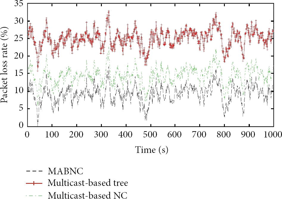
Packet loss rate.
4. Summary
This paper aims to design the requirements of multicast routing protocol based on WSN as follows: energy efficiency, expandability, robustness, and fast convergence. Based on network coding, k-redundant multicast protocol is proposed and its working process is described. The routing protocol is simulated at the platform of NS2.31. The simulation result indicates that the protocol routing has lower rate of packet loss, small delay, and relatively low cost of the entire network nodes.
Footnotes
Conflict of Interests
The authors declare that there is no conflict of interests regarding the publication of this paper.
Acknowledgment
The work supported by the National Natural Science Foundation of China (Grants no. 61103195, and no. 61373137).