
Abstract
Natural shark skin has a well-demonstrated drag reduction function, which is mainly owing to its microscopic structure and mucus on the body surface. In order to improve drag reduction, it is necessary to integrate microscopic drag reduction structure and drag reduction agent. In this study, two hybrid approaches to synthetically combine vivid shark skin and polymer additive, namely, long-chain grafting and controllable polymer diffusion, were proposed and attempted to mimic such hierarchical topography of shark skin without waste of polymer additive. Grafting mechanism and optimization of diffusion port were investigated to improve the efficiency of the polymer additive. Superior drag reduction effects were validated, and the combined effect was also clarified through comparison between drag reduction experiments.
1. Introduction
Shark skin effect has attracted worldwide attention over the past few decades because of its superior drag reduction property [1]. It was found that the hierarchical surface morphology with microscopic structure and nano-long-chain mucus was main structural characteristics of shark skin, which results in such amazing drag reduction.
The small riblets of shark skin work to reduce the increased drag present in turbulent flow in two ways: by elevating the high-velocity vortices above the skin and by impeding the cross-stream translation of the streamwise vortices in the viscous sublayer. The mechanism of riblets interacting with and impeding vortex translation is complex, and the entirety of phenomena is not yet fully understood. Impeding the translation of vortices reduces the occurrence of vortex ejection into the outer boundary layers and momentum transfer in the outer boundary layers [2]. Despite the superiority of shark skin in surface drag reduction, the straight U/V-shape microgroove is still predominantly applied in pipelines, airplanes, and so forth, due to the difficulty in manufacturing the complex hierarchical structures of shark skin. Undoubtedly, simplification of real shark skin into straight microgroove decreases drag reduction compared to real shark skin. The drag reduction rate of microgroove drag reduction surface has not reached 10% in the water tunnel test [3–7].
To overcome this drawback, the bioreplication forming process in which real shark skin is directly taken as a template has been attempted for the manufacture of a vivid biomimetic drag reduction surface with a microscopic structure [8, 9]. The drag reduction of bioreplicated biomimetic drag reduction surface has been experimentally shown to be 12.5%, which is more efficient than the traditional straight microgroove. Thus, the natural shark skin should have excellent drag reduction performance due to their synthetic effect of microscopic structure and nano-long-chain mucus.
Recently, synthetic drag reduction has been explored by directly pouring polymer additive into fluid or coating a conventional drag reduction riblet. Choi et al. found that the drag reduction of polymer coated U-groove riblets was superior to only U-groove in a towing tank on a one-third scale model of the America's Cup winning yacht, Australia II [10]. Mizunuma et al. experimentally tested the synergistic effects of turbulent drag reduction by directly pouring large quantities of polymer additive into the fluid [11–13]. Christodoulou et al. carried out experiments on a combination of riblets and polymers to make clear effect of Polyox 301 concentration on drag reduction [14]. Although a positive synthetic effect was demonstrated, almost all drag reduction surfaces were realized via the simple integration of the U/V microgroove with polymer additive, which have several serious problems such as (1) the difficulty in maintaining the groove shape and improvement of drag reduction which is limited by coating; (2) the immense waste of polymer additive by diffusion into whole fluid.
With the demands on energy efficiency and environmental preservation becoming more urgent, developing novel synthetic drag reduction to simultaneously achieve higher drag reduction and less consume of polymer additive is becoming more necessary than ever. In this paper, firstly the precision bioreplication process of shark skin is depicted. Two integration approaches of polymer additive for vivid shark skin are proposed; namely, polymer additive grafting (PAG) and microport diffusion are proposed. We investigated these approaches in terms of long-term maintenance and the diffusion microport optimization of polymer additive, respectively. Finally, the synthetic drag reduction of integrated vivid shark skin with polymer additive is validated by water tunnel test, and synthetic drag reduction mechanism is exploited.
2. Integration of Bioreplicated Shark Skin with Polymer Additive
It has been well known that the addition of a tiny amount of high molecular weight of linear flexible polymers into a turbulent flow can cause a considerable reduction in the skin friction drag [15]. With the higher molecular weight polymers giving better drag reduction performance, only parts per million levels of the polymers in the working fluid suppress the formation of turbulent bursts in the buffer region and in turn suppress the formation and propagation of turbulent eddies [16]. To achieve improved drag reduction performance, it becomes more necessary to efficiently combine drag reduction riblets with polymer additive.
2.1. Polymer Additive Grafting Synthesis
Polymer additive flowing away with fluid is the primary reason of polymer additive waste. To address this problem, grafting the polymer additive to the drag reduction surface by chemical bonding, that is, graft copolymerization, is worthy of extensive investigation.
The bicomponent silicone rubber RTV-2 875 with the A, B component, which is vulcanized at room temperature, was used as bioreplication dies because of their advantages such as low heat shrinkage, less surface energy, and excellent demolding performance. Polyacrylamide (PAM), that is, water-soluble linear polymer with molecular weight more than 3 million and chain segment length 0.25 nm, is chosen as drag reduction agent [17], whose chemical structural formula is shown in Figure 1(a). As another monomer of graft copolymer, waterborne epoxy resin composed of water-based epoxy resin emulsion (AB-EP-44) and waterborne epoxy curing agent (AB-HGF) was employed (Zhejiang Anbang New Material Development Co., Ltd.). Water-based epoxy resin emulsion is water-based bisphenol-A epoxy resin, whose chemical structural formula is shown in Figure 1(b).

Chemical structural formula of (a) polyacrylamide and (b) water-based bisphenol-A epoxy resin.
Amide groups of PAM reacting with the epoxy groups of water-based epoxy resin lead the ring-open reaction of epoxy groups to generate hydroxyl groups as shown in Figure 2. As a result of graft copolymerization, the nano-long-chain of PAM bonds with epoxy resin to prevent polymer additive from flowing away.

Equation (mechanism) of graft copolymerization.
A Fourier transform infrared spectrometer AVATAR 360 FT-IR was applied to determine the infrared spectrum of water-based epoxy resin film before and after grafting. Across the spectrum, the functional groups and structure of compounds can be identified from the functional group region and fingerprint region, respectively. Figure 3 shows the infrared spectrum of water-based epoxy resin film before and after grafting. One sharp absorption peak near 1666 cm−1, that is, the characteristic absorption peak of carbonyl groups on amide groups, appears after grafting, indicating that the grafting reaction generates a great number of amide groups. The magnitude of the obtuse round absorption peak near 3397 cm−1, which is the characteristic absorption peak of hydroxy groups, becomes larger after grafting. The characteristic absorption peak of epoxy groups near 830 cm−1 declines with grafting, which implies that the amount of epoxy groups descends. Therefore, the above-mentioned grafting copolymerization can be clarified by the appearance of carbonyl groups, the increment of hydroxyl groups, and the decrease of epoxy groups after grafting.
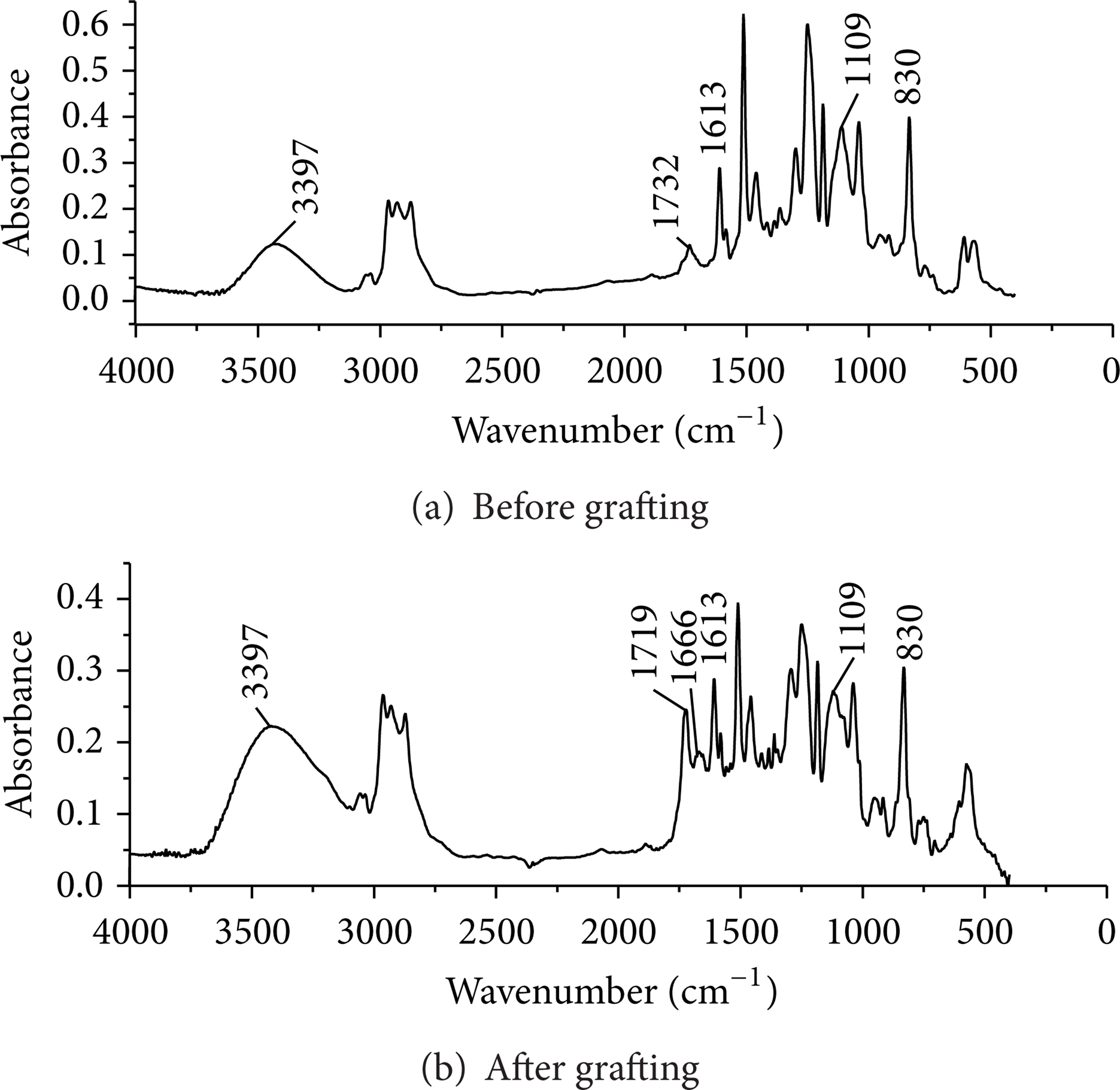
Infrared spectrum of water-based epoxy resin film before and after grafting.
The formation of synthetic bioreplicated shark skin based on polymer additive grafting can be divided into a four-step process as shown in Figure 4. This includes the pretreatment of shark skin, the molding of the elastic female die, the preparation of prepolymer, and the formation of synthetic bioreplicated shark skin. The skin of Carcharhinus brachyurous (1.4 m in length, Beijing Fishery Corp.), which is a typical kind of fast sharks, was taken as template of bioreplication.

The procedure of nanomicromultiscale synthetic bioreplication.
(1) Pretreatment of Shark Skin. Pretreatment of shark skin is of great importance in maintaining the surface morphology and improving the surface strength as a molding stamp. The pretreatment of shark skin generally follows six steps: slicing, cleaning, chemical fixing, rinsing, dehydration, and drying [8, 9, 18, 19].
(2) Molding of the Elastic Female Die. The mass of ingredients A and B of silicone rubber RTV-2 875, in which the mass ration of ingredient A to B is 100: 2, is determined on the basis of desired thickness and the area of the elastic female die. The mixture of ingredients A and B must be stirred well and then degas the air inside the mixture. The vacuum degassing process is conducted to squeeze air out of the cavities in the shark skin surface after pouring the mixture on the shark skin. Finally, the elastic female die of silicon rubber is cured and then demolded at room temperature.
(3) Preparation of Prepolymer. The graft copolymer of water-based epoxy resin and PAM is taken as a substrate of prepolymer of the synthetic drag reduction surface. First, a PAM solution with a mass concentration of 2% is prepared by slowly pouring PAM powder into water and simultaneously stirred to avoid formation of insoluble PAM micelle. Next, a water-based epoxy resin emulsion (AB-EP-44) is added into the PAM solution at the mass ratio of 1: 6 and is stirred to graft polymerization. A curing agent (AB-HGF) is added at the mass ratio of 1: 30 and plasticizer (dibutyl phthalate, DBP) at the mass ratio of 1: 80 and stirred for 20∼30 min again and the undissolved micelle is filtered out. Finally, the prepolymer is prepared after predegassing, which is performed to squeeze out the entraining air inside the prepolymer during stirring.
(4) Formation of the Synthetic Drag Reduction Skin. Vacuum degassing is conducted again to push prepolymer into cavities after pouring the prepolymer onto the surface of the elastic female die. Subsequently, the poured elastic female die is placed inside an electric blast drying oven at 60°C and cured for more than 10 h. Then the synthetic drag reduction skin with a nano-long-chain and microgrooves is simultaneously formed as shown in Figure 5.
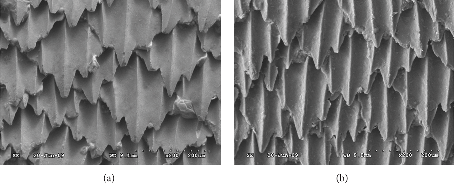
The SEM of the microgroove on (a) shark skin and (b) synthetic bioreplicated shark skin.
2.2. Optimization of Polymer Additive Diffusion Microport
Diffusion of polymer additive into the whole fluid via microports is another integration approach of vivid shark skin with polymer additive. The structural size and distribution of microport determine the concentration of the polymer additive on the outer surface. The polymer additive is diffused around the body surface through the elaborated microport array under gentle external pressure, whose schematics are shown in Figure 6. Diffusion microport optimization such as distribution, hole, and channel size is necessary to distribute minimal polymer additive uniformly. The microport array design and its fabrication especially do not sacrifice mechanical strength of the drag reduction skin.

Schematics of polymer additive diffusion.
According to Fick's law of diffusion, the concentration C(x,y,z) of polymer additive that is diffused through one microport can be given as [20]
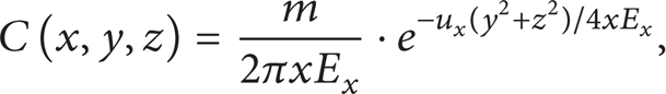
where E x is the turbulent diffusion coefficient, m is the mass of polymer additive diffused out per unit of time, and ux is the flow velocity along flow direction x of fluid.
Assuming the diffusion of the microport array with p ports in column and 2q ports in the row over the body surface, as shown in Figure 7, the overall concentration at region D can be presented by superimposition of the concentration diffused from each port:

Uniformly diffused layer of polymer additive can be more feasible by increasing the number of diffusion microports. Unfortunately, the fabrication of microports array becomes more difficult. Therefore, the number of diffusion microports must be minimized to keep the integrity of drag reduction skin without prejudice to the sound diffusion of the polymer additive over most of the body surface.

Diffusion structure of polymer additive.
Moreover, the microport aperture and channel size are optimally determined to ensure that the minimal external pressure diffuses sufficient polymer additives. Here, the detailed structure of the drag reduction microport array is chosen as e 13.5 mm; l 5 mm; microport diameter 0.8 mm; main channel 11 mm; and branch channel 6 mm. Overlying the bioreplicated shark skin with microport array upon a fluid channel layer which is fabricated via microwire mold (Figure 8) is one way to obtain synthetic drag reduction skin based on polymer additive diffusion.

Microwire mold fabrication of the microport array.
3. Results and Discussion
3.1. The Drag Reduction Test System
In order to validate the synthetic drag reduction, drag reduction rate is tested for various skins in a vacuole water tunnel. Figure 9 shows the test section of the system, in which the balance is covered with a guided flow dome to reduce the additional resistance. The parameters used in the test system are as follows.
The length of the test section in the vacuole water tunnel is 3.2 m with diameter 0.8 m.
The flow velocity in the test section is adjustable in the range 0∼20 m/s.
The central pressure of the test section can be changed in the range 8 kPa∼400 kPa.
The vacuole index is 0.15.

Schematic drawing of the test section.
The test models with a hollow elliptical sphere at front end and a hollow cylinder at the posterior segments are made from the aluminum alloy LY12. The size of the test model with a cylinder length 500 mm and an external diameter of 90 mm is determined according to the size of strain gauge balances of the test system. The polymer additive thruster and container are placed inside the test model in order not to affect the fluid flow.
Test skins are divided into two groups. The first group includes smooth skin (G-1), bioreplicated shark skin (G-2), and bioreplicated shark skin with diffusion ports (G-3) made from silicone rubber. The second group is made from waterborne epoxy resin, including smooth skin (H-1), self-lubricating skin (H-2), and polymer additive grafted synthetic drag reduction shark skin (H-3). Smooth skins are taken as a reference to calculate the drag reduction rate DR as
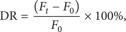
where F0 is the practical resistances of the smooth skin and F t is the practical resistances of the biomimetic drag reduction skin.
704 silicone sealant is used as adhesive because of its merits such as high water resistance, high adhesive strength, and long curing time, which allows enough time to adjust the position of skins after pasting. It should be noted that the height of skins should remain consistent during the pasting. The seam should be sealed and smoothed with 704 silicone sealant to avoid infiltration of water and formation of disturbed flow. Moreover, the direction of the microgroove in the skins should be consistent with the fluid flow direction.
Experiments are conducted following the rules of vacuole water tunnel test (Q/702J0301-2008). The water temperature is set at 28°C and the test system is degassed for more than 1 h before testing.
3.2. Drag Reduction of Polymer Additive Grafted Synthetic Drag Reduction Skin
Except for the smooth silicone rubber skins (G-1) which were washed off beyond 6.5 m/s, the water velocity of the other test skins is up to 8 m/s. The drag reduction rate curve is shown in Figure 10, indicating that the drag reduction rate of the synthetic drag reduction skin increases rapidly along with the velocity of water rising as water velocity is less than 3.5 m/s. While the drag reduction rate increases slightly, the water velocity exceeded 3.5 m/s. The drag reduction rate is up to 24.6% when the test terminates at velocity of 8 m/s. The synthetic drag reduction rate based on polymer additive grafting is throughout higher than that of the self-lubricating skins, while this rate surpasses the groove structure just after the water velocity rises to 3.9 m/s. As water velocity especially exceeds 5.5 m/s, the drag reduction rate of synthetic drag reduction surface is larger than the sum of the groove and the self-lubricating skins. Therefore, we predict that the synthetic drag reduction effect would become more remarkable as the water velocity increases.

The drag reduces rate curve.
At a low velocity range, the resistance of synthetic drag reduction surface is higher than the smooth skins as shown in Figure 11. This is because the long-chain of drag reduction additive stretching in water does not reduce drag when the water flow is laminar flow or when the turbulence intensity is weak. Even the hydrophilic groups of the long-chain of drag reduction additive hamper the water flow, which lead to increased resistance. Only with the velocity of water increasing, the drag reduction effect of long-chain gradually becomes remarkable.

The resistance curves (a) overall and (b) enlarged.
3.3. Drag Reduction of Polymer Additive Diffusion
The polymer additive diffusion was controlled by adjusting the diffusion pressure, and the drag reduction test experiments were conducted under varying conditions in terms of diffusion rate of the polymer additive and the flow velocity. The drag reduction of the smooth skin with diffusion ports was firstly compared with that of the smooth skin without diffusion ports. Results show that the resistance force remains unchanged; that is, the diffusion port hardly has impact on drag reduction. The drag reduction of the smooth skin (G-1) with varying polymer additive diffusion is shown in Figure 12. The drag reduction effect is often enhanced with more polymer additive diffused through port and generally decreases with fluid velocity increasing except for 3 m/s. As for the reason, it can be conceived that the faster the fluid flows, the faster the polymer additive diffuses and the concentration near the wall region declines. Moreover, the growth speed of the drag reduction slows down as more polymer additive diffuses, which results from saturation of the polymer additive. Figure 13 shows the experimental results of the synthetic drag reduction skin (G-3), through which we can see that the drag reduction amplitude of the synthetic skin is overall higher than smooth skin and even up to 80%, but the trend of polymer additive impact is similar.
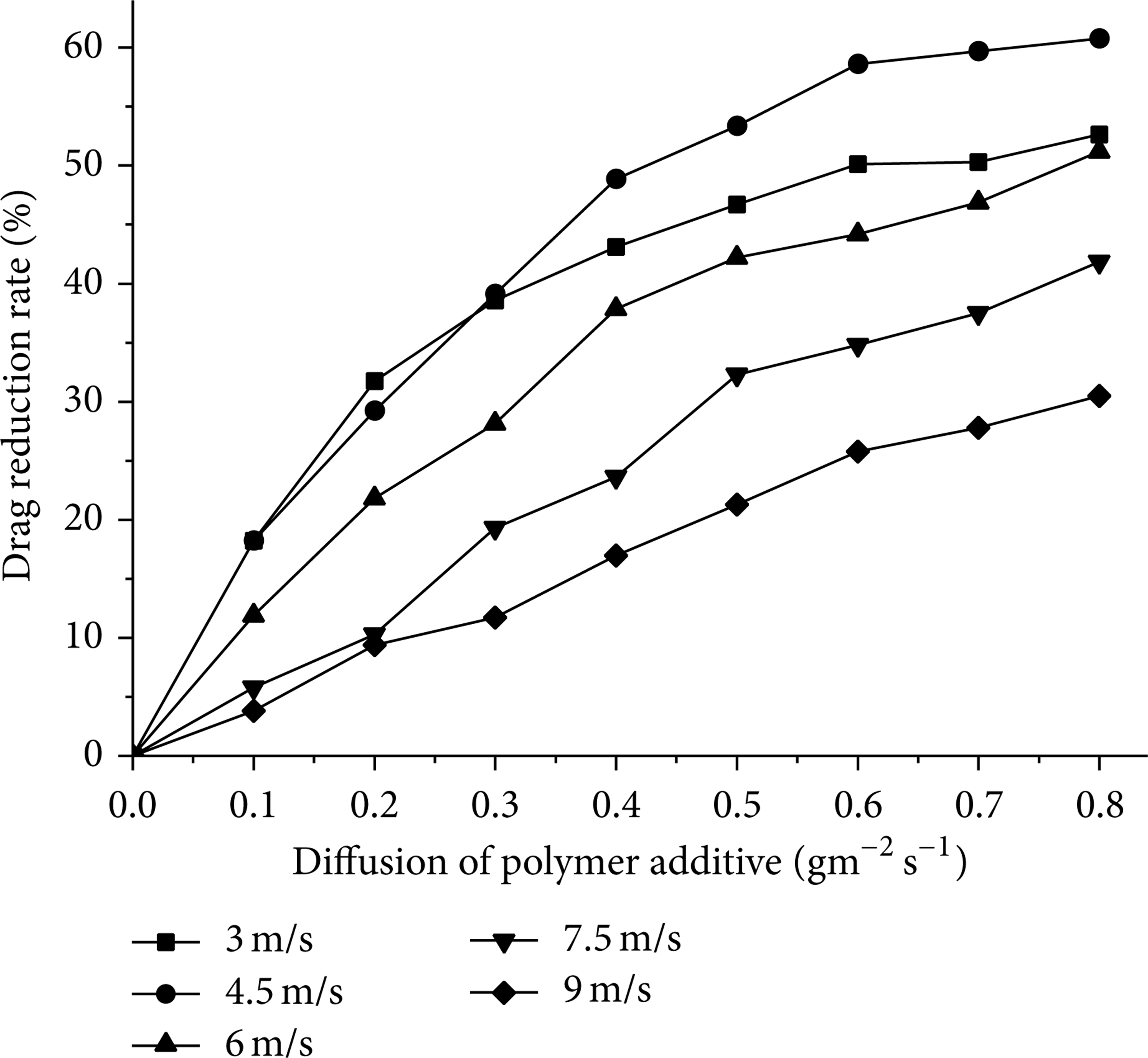
Drag reduction of polymer additive injected smooth skin.
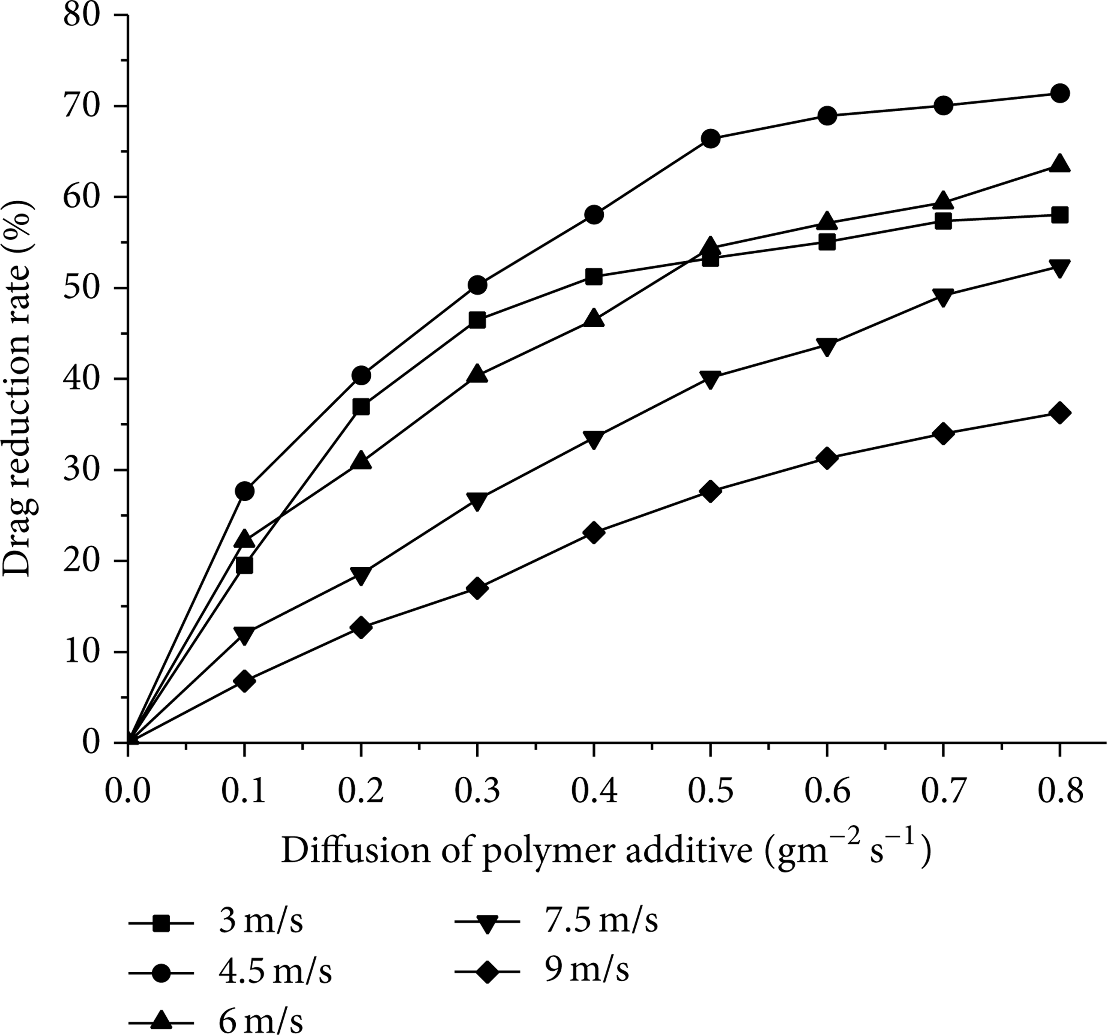
Synthetic drag reduction based on polymer additive diffusion.
The combined effect of drag reduction can be obtained by subtracting the drag reduction rate caused by the diffused polymer additive (G-1) and the microstructure of the shark skin (G-2) from that of the synthetic drag reduction skin (G-3), as shown in Figure 14. Although the combined effect generally grows stronger with more polymer additive injected and even rises to 5% as fluid flows at 9 m/s fluid velocity and 0.8 g/m2s polymer additive diffusion, it just appears to be positive at certain fluid flow conditions. The drag reduction mechanism analysis for shark skin demonstrated that superior drag reduction can be achieved just as the height of shark skin microstructure approaches the location of maximum turbulence intensity. And the location of maximum turbulence intensity gradually descends with increase of flow velocity, leading to a decline in the drag reduction. With respect to 30<s+ <40, since the location of maximum turbulence intensity goes below the height of the shark skin microstructure, injected polymer additive can enhance the thickness the viscous sublayer to make location of maximal turbulence near the height of the shark skin microstructure. This brings about the reinforcement of the drag reduction of shark skin microstructure, and a positive combined effect occurs. Whereas, as to 10<s+ <30, the location of maximum turbulence intensity approaches the height of the shark skin microstructure, the injected polymer additives unfortunately destroy their existing rationality without a positive combined effect [21].
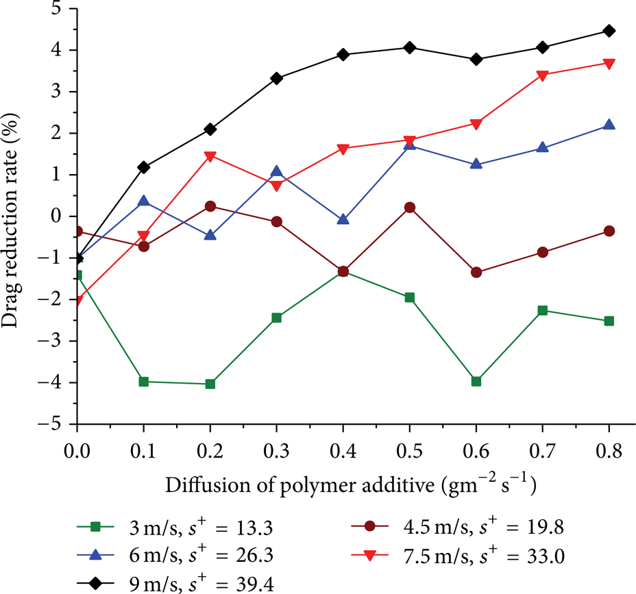
Combined effect in polymer additive injected synthetic drag reduction skin.
4. Conclusion
Synthetic drag reduction skin formation was proposed and investigated by combination of bioreplicated shark skin and polymer additive via long-chain grafting or microport array diffusion. The study of grafting mechanism and optimization of diffusion microport array were conducted to ensure a long-acting period and prevent a considerable waste of polymer additive. Various experiments were conducted to clarify the efficiency of the synthetic drag reduction skin. The following conclusions can be drawn from this study.
Polymer additive grafting to drag reduction skin was proposed and a grafting mechanism was clarified with Fourier transform infrared spectrometer.
Polymer additive diffusion ports were optimized to achieve a high drag reduction rate without much waste of polymer additive. The drag reduction rate reached up to 80%.
The combined effect was clarified in both synthetic drag reduction skins between the vivid shark skin and the polymer additive.
Conflict of Interests
The authors declare that there is no conflict of interests regarding the publication of this paper.
Footnotes
Acknowledgments
This work was supported by the National Natural Science Foundation of China (Grant 51175020) and NSFC Major Program (Grant 51290292).