
Abstract
This research is focused on evaluation of the magnetorheological fluids (MRFs) based damper which works in squeeze mode. The operation direction of this damper is parallel to the direction of the external magnetic field. Before testing, commercial software ANSYS was used to analyze the magnetic field distribution inside the damper generated by charging current in the coil. The performance of the damper was tested by using the MTS809 (produced by MTS Systems Corporation, USA). For simulation of this damper, a mathematical model was set up. Experimental results showed that the small squeezed MR damper could produce large damping force; for example, the maximum damping force is nearly 6 kN, while the amplitude is 1.2 mm, the frequency is 1.0 Hz, and the current is 2.0 A, and the damping force was controllable by changing the current in the coil. The damping force versus displacement curves are complex. We divide them into four regions for simulation. The maximum damper force increased quickly with the increasing of the current in coil. This kind of damper can be used in vibration isolation for precise equipment.
1. Introduction
Because of their unique rheological property, magnetorheological fluids (MRFs) have attracted wide research interests in various mechanical devices. One of the most popular MRFs devices is the MR damper filled with MRFs, which replaced the hydraulic oil in the automotive suspension system. For MR damper, a coil is usually used to provide suitable magnetic field. In contrast to conventional hydraulic damper, MR damper has the capability of changing its damping stiffness by changing the magnetic field intensity through controlling the current in the coil and the damping stiffness is the ratio between the damping force and the displacement which was provided during the working of damper. Together with embedded control system, MR dampers have gained increasing attention and their potential applications in enhancing the performance of suspension systems are discovered [1]. The MR damper was widely used in many fields with the control system, such as semiactive suspension system [2, 3], haptic feedback [4, 5], and medical devices [6]. Kinds of control systems have been researched [7, 8]. By using control system, we can control the damper simply. It is superior to commercial damper, because the damping force is easily controlled and the response is less than 10 ms; the structure of the MR damper is simple and has a long service life; it requires relatively low power to operate and the noise is low; it can be connected with a computer to achieve the aim of intelligent control.
The MR effect of MRFs is a typical characteristic for the MR damper and it appears when the MRFs are subjected to an external magnetic field. Since the carbonyl iron particles inside the MRFs form chains and clusters along the direction of the external magnetic field, the relative direction of the flow and the external magnetic field would affect the MR effect largely. Therefore, the rheological characteristics of the MRFs depended on the direction of the flow relative to the external magnetic field. The behavior of the MRFs can be divided into three categories according to the relative direction of the flow and the external magnetic field: valve, shear, and squeeze. Similarly, the MRFs based dampers also can be divided into four categories according to their working mode: valve mode damper, shear mode damper, squeeze mode damper, and hybrid mode damper.
Valve mode occurs when MR fluid is subjected to an external magnetic field whilst the MR fluid flows between two fixed parallel surfaces. This kind of damper had been widely used in many fields because of its simple structure. In addition, the MR damper working in valve mode was also used in other product, such as artificial limb and cable-stayed bridge [9]. Shear mode, also known as the clutch mode, occurs when MR fluid is subjected to an external magnetic field between two parallel surfaces. One of the surfaces is moving perpendicularly to the direction of the magnetic field while the other one is fixed. Dyke et al. and Yang et al. [10, 11] and Xu [12] have designed large-scale MR fluid damper used for vibration mitigation and seismic protection. The applications in other fields of the shear mode damper have been researched by Tu et al. [13]. Squeeze mode occurs when MR fluid is subjected to an external magnetic field between two parallel surfaces. One of the surfaces is fixed while the other one can only move parallel to the direction of the magnetic field. Though the motion range of the damper's piston is small, it can export larger damping force than the shear mode damper and the valve mode damper because of the larger compression yield stress. The MR fluid filled the cavity formed by the cylinder and the piston. When the piston moved up and down in the cavity, the MR fluid would be squeezed to flow to all around of the piston. The damping force could be controlled by changing the current intensity in the coil. The behavior of the MR fluids worked in squeeze mode had been studied by Farjoud et al. [14, 15] and Zhang et al. [16], respectively.
In the past, almost all the research on the rheological characterizations of MRFs is in the shear and valve modes, leaving the squeeze mode behind. There have appeared commercial dampers working in shear and valve modes and the researches on the damper working in squeeze mode are limited. In recent years, there has been increasing interest in researching on MRFs or electrorheological fluids (ERFs) working in the squeeze mode because of the larger yield stress. McIntyre and Filisko [17], Tian et al. [18], and Tian et al. [19] had performed experimental studies on compression of ER fluids under various conditions. Due to the similarity of the mechanisms between ERFs and MRFs, it is expected that the research findings in ERFs are available to the MRFs. Mazlan et al. [20] had investigated the compression behavior of two types of MRFs (water-based and hydrocarbon-based). They obtained strain-stress relationships for the fluids in the squeeze mode and concluded that the compression behavior of the fluids depends on the type of carrier liquid and magnetic field density. Guo et al. [21, 22] had investigated the squeeze behavior of the MRFs under uniform and nonuniform external magnetic field.
With more and more investigations on the squeezed behavior of the MRFs were taken out, the equipment working in squeeze mode appeared. Ahn et al. [23] and Carmignani et al. [24] have developed systems for rotor applications which depended on MR squeeze film damper. But the film damper system only can be used for clutches and brakes. In the film damper, the direction of the magnetic field relative to the moving direction of the MRFs is perpendicular. In this work, a damper is designed in which the MRFs are working in squeezed mode. A coil is put inside to provide magnetic field for the damper. The magnetic field distribution is analyzed by commercial software ANSYS. The performance of the damper is tested and the testing results are complex. Four regions have been divided for simulation.
2. Design and Analysis
2.1. Design of the Damper
The damper is designed according to the squeeze mode of the MRFs. The schematic of squeeze mode is shown in Figure 1. According to this schematic, a squeezed damper is designed. The schematic diagram of the squeezed damper is shown in Figure 2. Our damper is made up of shell, coil, piston rod, squeezed plate, and some seal rings. The images of the damper and the parts are shown in Figure 3. The parameters of the damper are listed in Table 1. It can be seen that the coil is installed inside the shell and separated with cavity of the damper by a copper plate. The squeezed plate is fixed together with the piston rod and is placed at the center of the shell. Before the damper is working, it is filled with MRFs in the cavity. To avoid the influence of the air bubbles, several steps have been taken before the MRFs are filled into the damper. Firstly, the MRFs are stirred energetically for 5 minutes to make MRFs dispersing uniformly. Then MRFs are placed in a vacuum environment for just 1 minute to remove the air bubbles. Finally, the MRFs are filled into the damper carefully and then the damper is sealed by two seal rings. An external magnetic field would be provided by the coil while the damper is working. When the piston rod is moving up and down, the squeezed plate fixed together with the piston rod will move in the cavity and squeeze the MRFs filled in the damper. While the MRFs are squeezed, they will flow around after yield and the flowing direction is perpendicular to the direction of the external magnetic field. The damping force can be controlled by changing the current in the coil to produce a suitable magnetic field for the damper. Because a large gap would reduce the density of the magnetic field, so the maximum displacement of the squeezed plate is small.
The parameters of the damper.


The schematic of squeeze mode.

The working schematic of the squeeze MR damper.
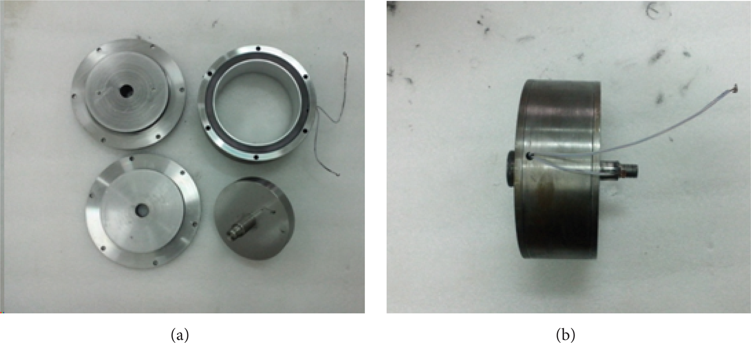
The images for the damper and the parts.
2.2. Analysis of the Magnetic Field
The MR effect of the MRFs is decided by the external magnetic field. So the design of the magnetic field is the most important part of the MRFs damper. The finite element analysis using ANSYS is used to simulate the distribution of the magnetic field in the damper. Because of the symmetry of the damper, we just need to build up a two-dimensional model of the damper to analyse the magnetic field. To reduce the reluctance of the damper, so as to increase the magnetic field intensity of the MR effect zone, the shell of the damper and squeezed plate are made of electrical pure iron (#DT3). The magnetizing curves of the shell and the MRFs are shown in Figure 4. The relative permeability of nonmagnetic piston rod and the copper plate is set as 1.
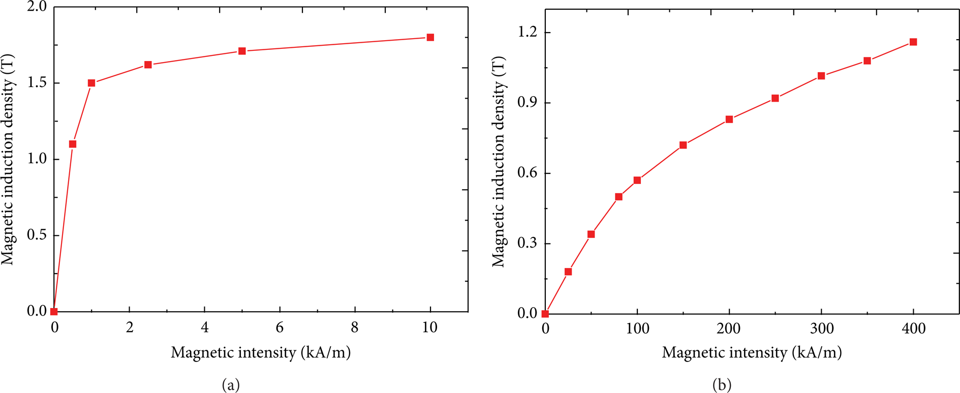
The magnetizing curves of the shell (a) and the MRFs (b).
The distribution of the magnetic field line simulated by ANASYS when the current is 1 A is shown in Figure 5(a). The result of the simulation indicates that the magnetic field line mainly focuses on the closing path formed by the damper. The magnetic field line in the squeezed area of the MRFs is perpendicular to the squeezed plate face and parallel to the direction of the squeeze. The distribution of the magnetic flux density simulated by ANASYS when the current is 1 A is shown in Figure 5(b). It can be seen that the distribution of magnetic flux density in the MRFs effect area is uniform. The magnetic flux density nearby the upper and lower surface of the squeezed plate is shown in Figure 6. Along with the increasing of current, the density of the magnetic field increases. When the current increases to 4 A, the magnetic density can only reach 0.27 T, much smaller than the saturated magnetization density for the MRFs. A large reluctance coming from the large gap between squeezed plate and shell leads to a low magnetic flux density.

The distribution of the magnetic field (a) and the magnetic flux density (b).

The magnetic flux density nearby the (a) upper and (b) lower surface.
3. Test
MRFs with iron volume fraction 30% and viscosity of the carrier liquid 500 cSt are used. The damper is filled with MRFs carefully to remove the air bubbles inside. Then, the damper is fixed on the MTS (produced by MTS Systems Corporation, USA) for testing, as shown in Figure 7. The current in the coil is provided by a DC electrical source (4INC-CK-HL, produced by ChaoYang Corporation in China) and the current can be adjusted to provide a suitable magnetic field density in the damper. The test is taken out to gain the relationship between the damper force and the displacement under different amplitudes, frequencies, and currents. The excitation provided by MTS is sinusoidal.

The test system of the damper.
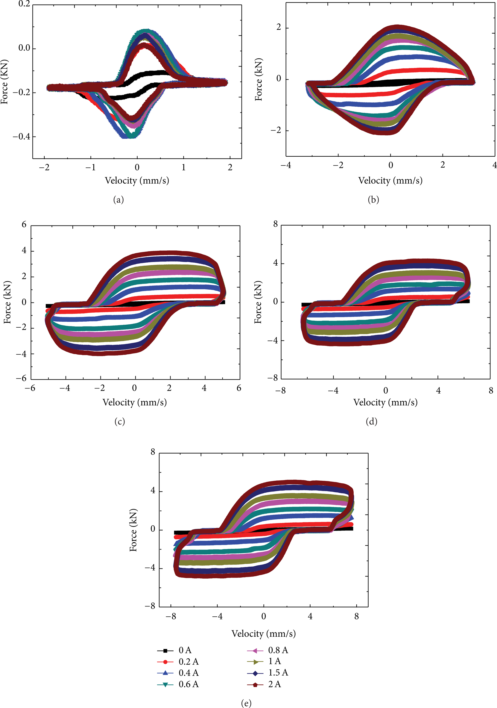
The testing alterable parameters used in this test include current, amplitude, and frequency. The current is set as 0 A, 0.2 A, 0.4 A, 0.6 A, 0.8 A, 1.0 A, 1.5 A, and 2.0 A, respectively. The amplitude is set as 0.3 mm, 0.5 mm, 0.8 mm, 1.0 mm, and 1.2 mm, respectively. The frequency is set as 0.1 Hz, 0.5 Hz, and 1.0 Hz, respectively. The amplitude, frequency, and current are kept constant in every testing. The curves for damping force versus displacement for different current, amplitude, and frequency are similar except for the maximum damping force. For simplicity, only parts of the testing results are shown here. Curves for damping force versus displacement under different current and amplitude are shown in Figure 8, and the testing frequency is 1.0 Hz. The maximum damping force increases rapidly along with the increasing of the amplitude. It can be seen that the curves for different amplitudes are similar and complex; the damping force is negative and then decreases rapidly just when the squeezed plate goes back from the maximum displacement; then, the damping force increases fast after adjustment while the squeezed plate moves to another side and reaches a constant finally. With the increasing of the current in the coil, the damping forces increase and the areas surrounded by the curves are increasing, too. That is to say, the damper can absorb more energy. Curves for damping force versus velocity under different currents and amplitudes are shown in Figure 9. It shows that the damping force reaches the maximum when the piston velocity is zero. Curve for maximum damper force under different current is shown in Figure 10. It shows that the maximum damper force increases rapidly with the increasing of the current. The regulable range of the damper force is extensive. Curves for amplitude of 1.2 mm and current of 2.0 A are shown in Figure 11. The damping force is increasing inconspicuously while the frequency is increasing. Curves for frequency of 1.0 Hz and current of 2.0 A are shown in Figure 12. The maximum damping force and the areas surrounded by the curves are all increasing with the increasing of the amplitude. This was because the squeeze of the MRFs is severe when the damper is subjected to a larger amplitude. The rheological properties of the MRFs when subjected to an external magnetic field are responsible for these peculiar phenomena. The analysis of the damping force and the mathematical simulation are discussed in next section.

Curves for damping force versus displacement under different currents and amplitudes: (a) 0.3 mm, (b) 0.5 mm, (c) 0.8 mm, (d) 1.0 mm, and (e) 1.2 mm.
Curves for damping force versus velocity under different currents and amplitudes: (a) 0.3 mm, (b) 0.5 mm, (c) 0.8 mm, (d) 1.0 mm, and (e) 1.2 mm.
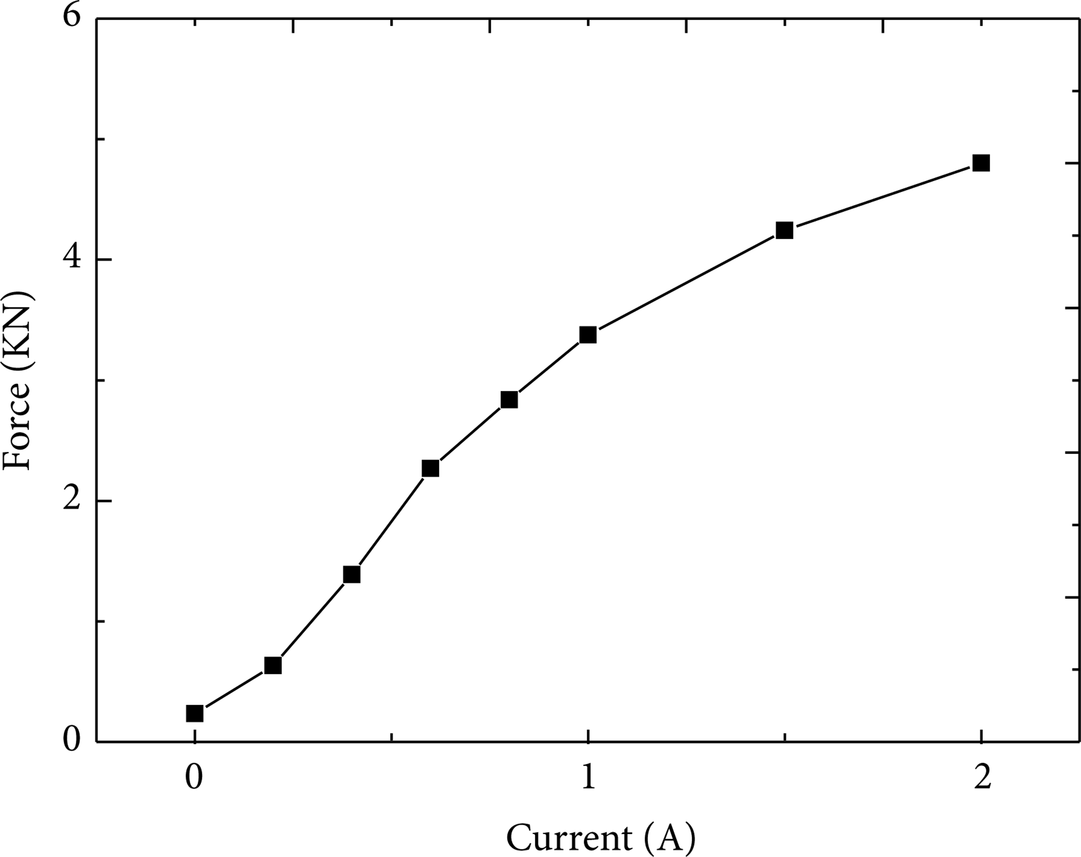
Curve for the maximum damper force under different currents.
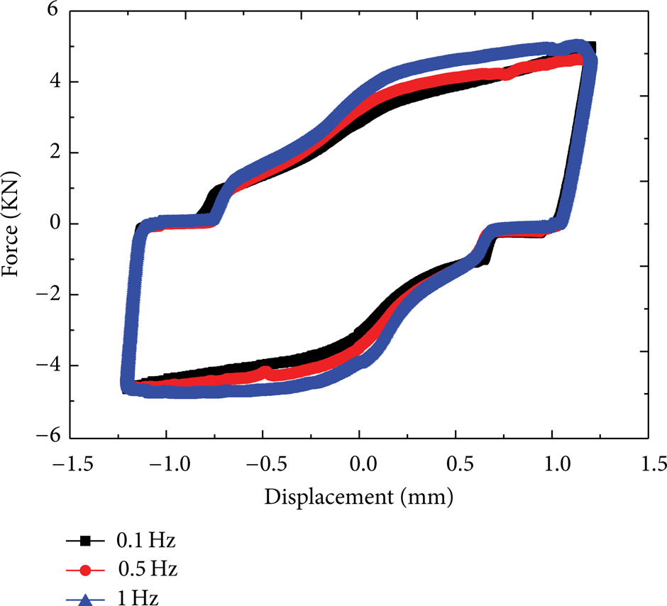
Curves for damping force under different frequencies.

Curves for damping force under different amplitudes.
4. Analysis of the Damping Force
We can see from the results of the test that the curves of the damping force versus the displacement for different conditions are complex. Since the curves are centrosymmetric, we can just analyze the upper half and it is shown in Figure 13(a). The damping force changes complexly when the piston moves from one side to another. According to the change of the damping force, we can divide the curve into four regions as shown in Figure 13(a). In region one, the damping force is negative and decreases rapidly along with the displacement. This region is narrow and it converts to region two quickly. In region two, the damping force is small and keeps nearly unchangeable. In region three, the damping force increases dramatically along with the displacement. Then, the damping increases slowly in region four.

The damping force versus the displacement. (a) Simulation and (b) experiment.
While the piston is moving in the damper, the MRFs are squeezed and stretched continuously. The MRFs would be stiff under the effect of magnetic field when they are squeezed to one side by the piston and there will be elastic energy reserved in the MRFs [14]. The piston would be rebounded by the elastic energy reserved in the MRFs just when the moving direction of the piston changes and this stage is completed rapidly. The MRFs would provide a thrust but not a resistance, so the damping force is negative in this region. The attenuation of the elastic energy is fast and then region two appears along with the moving of the piston quickly. Because of sealing effect, carbonyl iron (CI) dispersed in the MRFs aggregates at the ends of damper [22]. Volume fraction of CI in the MRFs is low at the middle of the damper and region two appears at this zone. While piston is moving in this region, MR effect is weak because of low volume fraction. So the damping force mainly produces by viscidity of the based liquid and this force is quite small. Along with the piston moving unceasingly, sealing effect appears and the volume fraction of CI increases; then, region three appears. In this region, CI particles in the MRFs align forming particle chains to the direction of the external magnetic field and lead to a large yield stress. Along with the increasing of the volume fraction of CI which is led by sealing effect, the yield stress increases and leads to an increasing damping force. The sealing effect reaches a limitation gradually with the movement of the piston and then region four appears. In this region, the volume fraction of CI no longer increases and the size of the particle chains which form in region three is no longer increased, either. So the damping force is unchanged sharply.
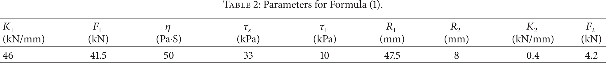
Based on the analysis above, the damping force can be described as shown in Formula (1); s is the displacement of the piston, K1 and F1 are decided by the maximum damping force and the rate of decay of the elastic energy, η is the viscosity of the based fluid,
Parameters for Formula (1).
We get the simulative result by taking the experimental parameters into Formula (1) and the result is shown in Figure 13(b). We can see that the simulative result is suited with the tested result shown in Figure 13(a). Consider
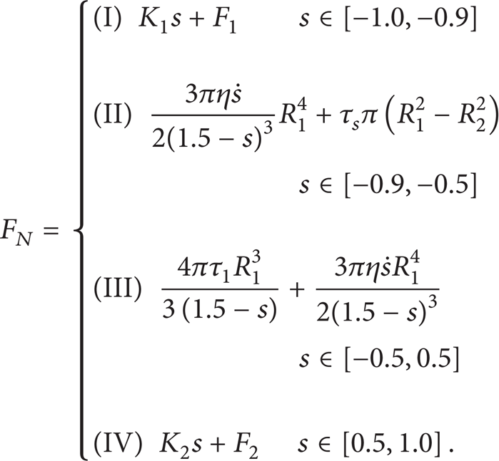
In the first region, damping force changes linearly with the displacement because of the stiffness of the squeezed MRFs. In the second region, the MR effect is so weak that the damping force is mainly provided by the viscous force and tensile force provided by the MRFs. The viscous force and tensile force are both very small, so damping force is small in this region. In the third region, the MR effect is more and more remarkable with the increasing of the volume fraction of CI caused by sealing effect. Because of the high shear yield stress of the MRFs, the damping force is high in this region. In the fourth region, the damping force is constant because the volume fraction of CI is generally constant.
5. Conclusion
In this work, a MRFs based damper working in squeezed mode is designed. After analyzing the distribution of the magnetic field by using commercial software ANASYS, we find that the magnetic field is uniform in the gap. The MTS testing indicated that the MR damper exhibits an excellent performance, and the maximum damping force is nearly 6 kN when the amplitude is 1.2 mm. Though the size of damper is small, the generated damping force is large which should be benefited from the large squeezed yield stress of the MRFs. It is observed that the relationship between damping force and displacement is complex. For simulating the complex curves, we divide them into four regions. They are rebounded region, out of operation region, MR effect region, and saturated region, respectively. Every region has been analyzed in detail.
Conflict of Interests
The authors declare that there is no conflict of interests regarding the publication of this paper.
Footnotes
Acknowledgments
Financial supports from the National Natural Science Foundation of China (Grant nos. 11125210, 11102202, and 51205100) and the Funds of the Chinese Academy of Sciences for Key Topics in Innovation Engineering (Grant no. KJCX2-EW-L02) are gratefully acknowledged.