
Abstract
Recently, carbon fiber reinforced plastic (CFRP) with high strength, stiffness, and lightweight is used widely in number of composite applications such as commercial aircraft, transportation, machinery, and sports equipment. Especially, it is necessary to apply lightweight materials to car components for reducing energy consumption and CO2 emissions. In case of car roof reinforcement manufactured using CFRP, superior strength and bending stiffness are required for the safety of drivers in the rollover accident. Mechanical properties of CFRP laminates are generally dependent on the stacking sequence. Therefore, research of stacking sequence using CFRP prepreg is required for superior bending stiffness. In this study, the 3-point bending FE-analysis for predicting the bending stiffness of CFRP roof reinforcement was carried out on three cases
1. Introduction
Due to steadily rising oil prices and environmental regulations, lightweight parts for transportation systems are now in high demand. In particular, to lighten the weight and increase the stiffness of automobile parts presently manufactured with conventional steel materials, lightweight alternative materials such as aluminum, magnesium alloy, and composite materials are being applied. Among them, carbon fiber reinforced plastic (CFRP), a representative lightweight material with specific strength and stiffness superior to metals, is considered to be the material to replace conventional metals.
In general, there are three steps in CFRP manufacturing processes. The steps are (a) stacking prepregs, which are woven fibers impregnated with epoxy resin, in a specific sequence, (b) press forming them into the desired product form, and (c) curing the resin by raising the temperature to 130°C and maintaining it with the prepreg in a press die. Generally, the mechanical properties of CFRP products such as tensile strength and bending stiffness are determined by the prepreg fabric structure and stacking sequences [1–3]. Therefore, various studies on prepreg fabric structure and stacking sequences have been conducted to enhance product strength and stiffness in CFRP product design. Fuhong et al. [4] manufactured a composite product where unidirectional prepregs were [0°/90°] cross-laminated and studied the effect of the structure support point on the product stiffness. Zhang [5] varied the stacking angle of unidirectional prepregs by 15° to get stacking sequences of [0°/ ± 15°/90°] s , [0°/ ± 30°/90°] s , [0°/ ± 45°/90°] s , and [0°/ ± 60°/90°] s . They predicted the bending strength according to the stacking angle, and this was applied in the manufacturing of a wind turbine blade. Yudhanto et al. [6] evaluated the effect of the stacking angle for plain weave prepregs on CFRP failure through tensile test of hole-machined CFRP.
However, most of such studies have only used prepregs of a single fabric structure to predict the strength and stiffness of the CFRP structure under varied stacking angles. Recently, using FE-analysis, researches have predicted the strength and stiffness of CFRP products using prepregs of different fabric structures. When stacking prepregs of different fabric structure, the analysis is performed after modeling the product and considering the properties and thickness of each prepreg. However, analysis by modeling the fabric and matrix consumes a significant amount of computation time. This method can only be applied to predicting microfracture of CFRP products with simple form and has been reported to be unsuitable for structural strength analysis [6–10]. Therefore, further research is necessary to enable the evaluation of material properties and strength analysis based on fabric structure, in order to predict the stiffness of CFRP products.
In this paper, hybrid laminates using plain weave and unidirectional prepregs of different fabric structures were used to fabricate an automobile roof reinforcement and to investigate the prediction of its bending stiffness and strength. The material properties needed in the FE-analysis for the bending stiffness prediction were obtained through the tensile tests of each cured plain weave and unidirectional prepreg. The 3-point bending analysis and tests were conducted for cured CFRP plate specimens, which were manufactured by stacking sequences following the sequences of
2. Establishment of Bending Stiffness Prediction Model for CFRP Structure
2.1. Tensile Test of Cured CFRP
In order to conduct strength analysis of the CFRP product, the mechanical properties of the cured plain weave and unidirectional CFRP were obtained through tensile test. The prepreg (C127-3K) used in the test was manufactured by Hyundai fiber. As shown in Figure 1, a hot press equipment was used to manufacture plain weave and unidirectional CFRP plates of 1 mm thickness. The manufacturing process begins by stacking CFRP prepregs, which have been cut into dimensions of 300 × 300 mm in the 0° direction. Also, a release film was placed on the upper and lower surfaces of the prepregs that come into contact with the die for prevention of sticking problem. Lastly, a hot press was used to manufacture the CFRP plates, which were cured through pressure and heat processes.
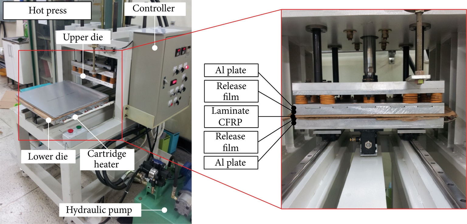
Equipment and process of hot press forming.
Figure 2 shows the CFRP mounted on the tensile test machine and the CFRP specimen before and after tensile test. The tensile specimens were fabricated in the 0°, 45°, and 90° directions with dimensions of 250 × 25 mm in accordance with ASTM D3039. Additionally, aluminum tabs were attached to each side of the specimens in order to prevent fracture by the applied pressure of the hydraulic grips [11].

Tensile test of CFRP specimen.
The tensile test results of the cured plain weave CFRP showed that the E11 and E22 were 72.48 GPa, G12 was 14.08 GPa, and ν12 was 0.174, respectively. For the cured unidirectional CFRP, E11 was 141.52 GPa, E22 was 7.35 GPa, G12 is 9.36 GPa, and ν12 was 0.24, respectively. The values of E11, E22, G12, and ν12 obtained experimentally were substituted into (1) for orthotropic materials to calculate the shear modulus G13, G23 [12]. Here, G13 and G23 of the plain weave CFRP are equal and the thickness direction material property, E33, was assigned the same value as the unidirectional E33, which represents the matrix property. Similarly, G12 and G13 are of equal value for the unidirectional CFRP. Table 1 shows the properties of each material obtained through the relationship equations:

Mechanical properties of plain weave and unidirection.

2.2. Overview of CFRP Prepreg Stacking Sequence
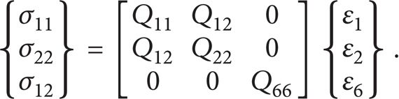
The CFRP used in this study was orthotropic, where the plies interact with each other and are adhered by the matrix to support the structure. Thus, the tensile strength and bending stiffness of the structure are determined by the stacking angle between the plies and the fabric structure. The stacking angle of the plies was determined, to obtain the required bending stiffness by using the conventional bending stiffness prediction equation. Equation (2) expresses Hooke's law of orthotropic material for plane stress. Since the thickness direction stresses σ33, σ13, and σ23 applied to each ply layer are much smaller than the in-plane stresses σ11 and σ22, the stress components were assumed to be 0:
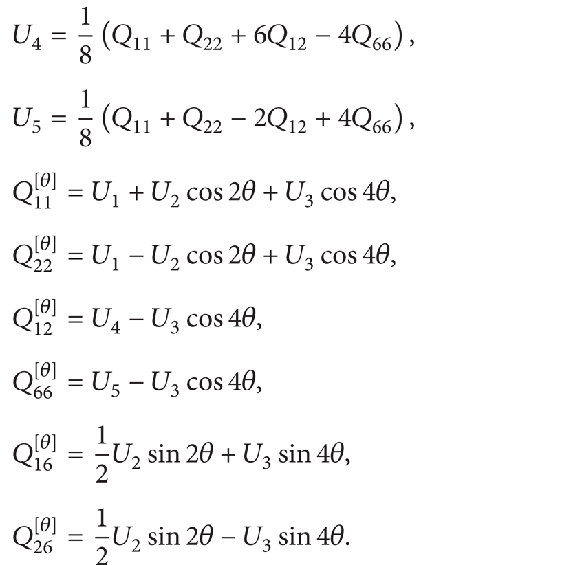
Equation (3) shows the invariants obtained using the trigonometric functions and formulas of multiple angles, with the conversion value of stiffness matrix based on the ply stacking angle [13]. Using the obtained invariants, the variation in bending stiffness according to the stacking angle was calculated using (4). The stress roller was lowered to the symmetric plane of cured CFRP with both sides of the specimen fixed so that bending occurs in the 0° ply direction. Accordingly, the CFRP bending stiffness is most significantly affected by the Q11 value. Therefore, the stacking angle of the plain weave and unidirectional prepreg in the 3-point bending test was set to 0° where the bending stiffness is maximum [14]:

2.3. Conditions of FE-Analysis and Test for 3-Point Bending
To perform FE-analysis of the CFRP, the thicknesses of the plain weave and unidirectional CFRP were measured. Generally, when stacking is done to be

Cross-sectional images of laminated CFRP.

Manufacturing process of laminated CFRP (simple plate).
FE-analysis of the 3-point bending test was conducted using material properties measured in Section 2.2. Figure 5 shows the FE-model where the specimen length, width, and thickness are 120 × 20 × 1 mm. The bending tests were categorized into three types according to the stacking sequence and angle: case 1
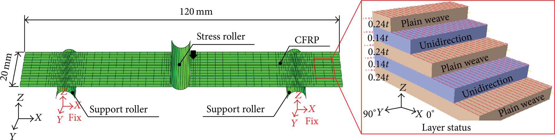
FE-model for the 3-point bending test.
In order to validate the FE-analysis model, the 3-point bending tests were conducted for CFRP plate specimens cured under the same condition as the product. To minimize dimensional error and delamination in the test specimens, water-jet cutting was used to manufacture the specimens. To prevent distortional failure during the bending test, guides were used to place the specimen in the test position. Figure 6 shows the 3-point bending test equipment where a universal test machine (MTS, 10 ton) was used to conduct the test at the constant rate of 12 mm/min.
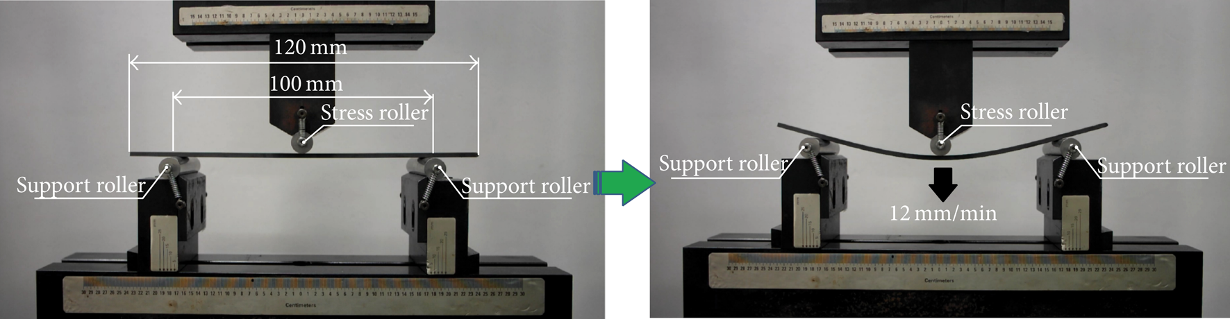
Experimental setup for the 3-point bending test.
2.4. Results of FE-Analysis and Test for 3-Point Bending
To establish the reliability of the FE-analysis, the deformation resulting from varied stress roller strokes was compared. The deformed shape of CFRP specimens was compared for various stress roller strokes, as shown in Figure 7. It was determined that the bending deformation behavior of cured CFRP was well simulated, as the forms were all similar for each stroke.

Shape comparison between FE-analysis and experiment.
Figure 8 shows a graph of stress roller stroke versus various bending load. In this study, the bending stiffness was defined as the maximum bending load divided by the stroke. Case 3, which is tested by the specimen with only stacked unidirectional CFRP prepregs, was found to have the highest bending load of 1236 N. Case 2, which was hybrid-laminated using both unidirectional and plain weave CFRP prepregs, and case 1, which had only stacked plain weave prepregs, showed bending loads of 789 N and 413 N, respectively. The following explains the causes behind the specimen results, including why the unidirectional prepregs had the highest bending loads. First, cured CFRP exhibit elastic deformation behavior, and the 0° direction of Young's Modulus and E11 values for the unidirectional CFRP is relatively higher than the plain weave CFRP E11 value. Second, in the case of case 3, a cross section of the unidirectional CFRP revealed that the greatest amount of carbon fiber was laminated in the longitudinal direction (0°) which represents the bending resistance.

Load-stroke graph of the 3-point bending test.
Observing the deformation of the specimen and the FE-analysis and experimental load graphs, all cases showed the same trend and values. Thus, the FE-analysis model presented in this study was determined to appropriately predict the deformation of the cured CFRP structure. However, it should be noted that the 3-point bending test compared the load of the stress roller per stroke for bending of a simple CFRP plate. The stacking sequence to satisfy the required stiffness may differ when predicting the bending stiffness of the real products.
3. Application of Bending Stiffness Prediction Model: Automobile Roof Reinforcement
3.1. Conditions of FE-Analysis and Test
Structural analysis of the automobile roof reinforcement was conducted using the bending stiffness prediction model validated through the analysis and experiments of the 3-point bending test. Figure 9 shows the FE-model for an automobile roof reinforcement. A symmetric analysis model with fixed boundary condition at one end was used and the stress roller was located at the symmetry plane. The thickness of roof reinforcement was 1 mm and a total of 5 plies were laminated. The stacking angle was 0° for all, and the three stacking arrangement cases of case 1

FE-model of roof reinforcement.
The same stacking condition and die as the FE-analysis were used and the fabrication test of CFRP roof reinforcement was performed using the hot press shown in Figure 10(a). The temperature of the die was controlled using a cartridge heater inserted into the upper and lower dies. Figure 10(b) shows the curing cycle of the epoxy resin. The manufacturing process of the roof reinforcement was as follows. First, 5 layers of prepreg cut into 1200 × 250 mm shapes were stacked according to the conditions of case 1, case 2, and case 3 and then placed on the lower die. In order to prevent the prepreg being stuck to the die, a high temperature liquid release agent was sufficiently spread to the upper and lower die surfaces. To increase the formability of the laminated prepregs, curing was done after preheating at 60°C which is the temperature at which epoxy resin softens. Also, the laminated prepregs were maintained at 80°C for 20 minutes so that the resin would be evenly distributed within the die. Lastly, after undergoing curing for 90 minutes at 130°C, the curing temperature of epoxy resin, a cooling process was conducted to complete the manufacture of the roof reinforcement [15]. Roof reinforcements that is fabricated by means of three cases of stacking sequence were evaluated by bending tests under the same conditions of FE-analysis as shown in Figure 11.
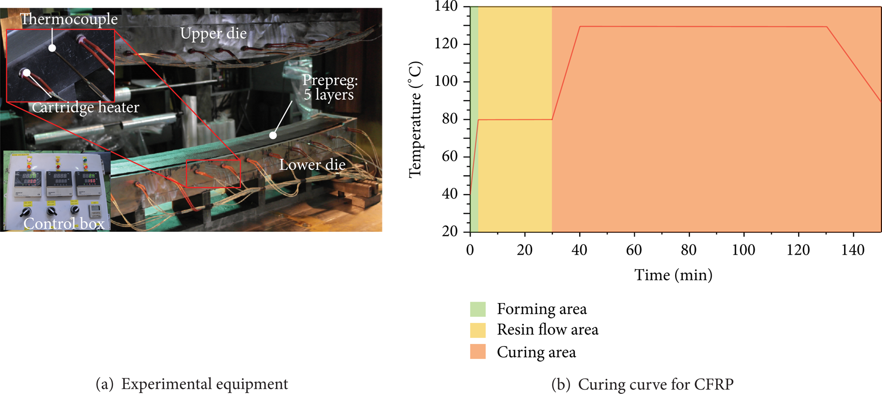
Equipment of hot press forming and curing curve for CFRP.

Equipment for the 3-point bending test of roof reinforcement.
3.2. Results of FE-Analysis and Test
To observe whether tearing occurred, the surface of the manufactured CFRP roof reinforcement was investigated. As shown in Figure 12, tearing defects which can occur at the wall and corner sections during forming were not observed for case 1 and case 2, which had plain weave laminated CFRP on the product surfaces. On the other hand, case 3, which had unidirectional CFRP laminated on the surface, was found to have tearing defects at the wall and corner sections [16]. Such tearing defects degrade the strength of the product, so using a woven prepreg material with high resistance to external deformation as the surface laminate material in the hot press forming process is justified.
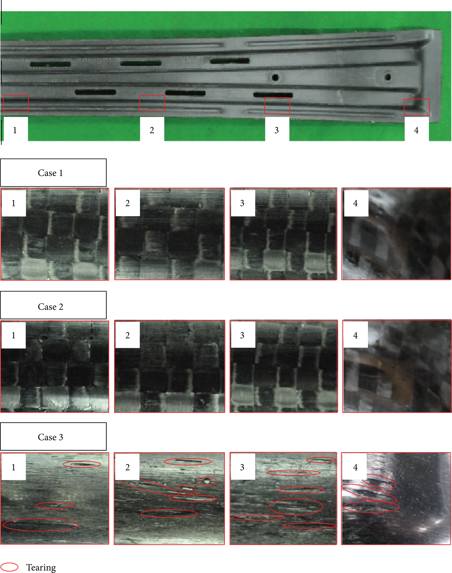
Surface observation of roof reinforcement.
Figure 13 shows the results of bending test for CFRP roof reinforcement, as the load per stroke of the stress roller. As a result of comparison between FE-analysis and experiment, the bending loads were similar at the initial and final stroke. However, differences of bending loads between FE-analysis and experiment in the middle stroke were observed for all cases. In FE-analysis the use of material properties of cured plain weave and unidirectional CFRP manufactured by hot press forming with flat dies may result in these differences due to a bit of constrained flows of resin and carbon fibers in roof reinforcement with channel shape.

Comparison between FE-analysis and experiments through load-stroke graph.
The bending analysis and test results were the same for case 2, with a maximum of 418 N, and for case 1, with a minimum of 276 N. In the case of case 3, it was found that the load results of the analysis and experiment had an error of approximately 100 N. As mentioned in Section 3.1, the FE-analysis predicted the bending load for an ideal state. However, the load was found to be lower in the real experiment as the product strength was degraded due to the tearing during manufacture. In the initial interval, the load increases with the same trend between the 3-point bending analysis and test results of the plate specimens, but after the point where the stroke is approximately 10 mm, the load of case 2 was measured to be relatively higher than that of case 3. The roof reinforcement in case 3 experiences loads differently from plate specimens, because bending occurs in the longitudinal direction x-axis as well as the width direction y-axis due to the flexure of the roof reinforcement shape. Therefore, bending stiffness decreased for case 3 where only unidirectional prepregs were laminated, as they exhibit low stiffness in the y-axis direction.
Figure 14 shows the velocity field of the cross section for deforming roof reinforcement, and it was found that bending deformation occurs in the y-axis direction, which is the minor axis. Through this result, it could be predicted that when only unidirectional prepregs are laminated, fracture will occur first in the width direction rather than the longitudinal direction in the bending test of real products.

Velocity distribution at cross section of roof reinforcement on the transverse direction.
4. Conclusions
In this study, the material properties of cured plain weave and unidirectional CFRP were measured in order to predict bending stiffness according to the CFRP stacking sequence. Validation of bending stiffness prediction model was performed by comparing the load per stress roller stroke through 3-point bending analysis and test. Moreover, the proposed prediction technique was applied to manufacturing of an automobile roof reinforcement to verify the reliability of the analysis.
In order to predict the stiffness of CFRP composed of a multiple layer structure, it is necessary to determine the material properties of the laminated materials of plain weave and unidirectional CFRP. Tensile tests were conducted to measure the elastic modulus E11 and E22 in the 0° and 90° directions and shear modulus G12 and Poisson's ratio ν12 in the 45° direction. Additionally, since both materials are orthotropic, G23 and G13 values were calculated using the related Hooke's law. The tensile test results of the cured plain weave CFRP show that the E11 and E22 were 72.48 GPa, G12 was 14.08 GPa, and ν12 was 0.174, respectively. For the cured unidirectional CFRP, E11 was 141.52 GPa, E22 was 7.35 GPa, G12 is 9.36 GPa, and ν12 was 0.24, respectively.
To validate the CFRP bending stiffness prediction model, the 3-point bending test was conducted using plate specimens. Analysis and test were conducted for 3 cases of stacking arrangement: case 1
When unidirectional prepregs are laminated on the surface, strength can be degraded due to tearing. Thus, when fabricating CFRP products using a hot press, the material laminated on the surface has to be a woven material with regular deformation resistance in the 0° and 90° directions. Also, it is preferable to use unidirectional prepregs as the internal stiffness reinforcing material.
Unlike the simple plate form, the roof reinforcement has a complex form, and so bending occurs in the 0° as well as 90° direction. Therefore, case 2
Conflict of Interests
The authors declare that they have no conflict of interests regarding the publication of this paper.
Footnotes
Acknowledgment
This work was supported by the National Research Foundation of Korea (NRF) Grant funded by the Korean government (MSIP) (no. 2012R1A5A1048294).