
Abstract
A double coil magnetorheological (MR) valve with an outer annular resistance gap was designed and prototyped. The finite element modeling and analysis of double coil MR valve were carried out using ANSYS/Emag software, and the optimal magnetic field distribution and magnetic flux density of the double coil MR valve were achieved. The mechanism of the pressure drop was studied by building a mathematical model of pressure drop in the double coil MR valve. The proposed double coil MR valve was prototyped and its performance was experimentally evaluated. The new MR valve design has improved the efficiency of double coil MR valve significantly.
1. Introduction
A hydraulic system is widely used in industrial applications where large inertia and torque loads have to be handled. Various types of valves have been adopted as control parts in the hydraulic system. Among them, an electrohydraulic servo control valve is frequently used to achieve accurate and fast control responses, such as precise position and speed control applications [1]. However, the electrohydraulic servo control valve system is complex, expensive, and slow in time response. Therefore, alternative actuating mechanisms for hydraulic system have been investigated to replace the conventional one.
Recently, one of the effective methods is to use a magnetorheological (MR) fluid which is a suspension of microsized particles dispersed in nonmagnetic carrying fluids [2]. Such fluid exhibits unusual characteristics in that their rheological properties can be continuously and reversibly changed within milliseconds by solely applying or removing magnetic fields. This interesting property has inspired the design of a large variety of MR devices in various engineering applications such as MR valves [3, 4], shock absorbers and dampers [5, 6], and engine mounts and clutch systems [7, 8].
MR valve is generally used to control the speed of hydraulic actuator of MR fluid. Using MR valve in hydraulic systems accrues many advantages, including the following: valves have no moving parts, eliminating the complexity and durability issues in conventional mechanical control valves, providing a direct transduction from an electrical control signal to a change in mechanical properties [9, 10].
In recent years, the research of MR valves aims to get large pressure drop or fast response by designing a novel structure or optimizing an existing structure. Rosenfeld and Wereley [11] proposed an analytical optimization design method for MR valves and dampers based on the assumption of constant magnetic flux density throughout the magnetic circuit to ensure that one region of the magnetic circuit does not saturate prematurely and cause a bottleneck effect. Nguyen and Choi [12–14] presented the geometric optimal design of MR valves constrained in a specific volume using the finite element method to improve valve performance such as pressure drop. Li et al. [15] optimized the design of a high-efficiency MR valve using finite element analysis with a maximum block pressure over 1900 kPa. Salloom and Samad [16] developed a new type of MR valve, in which the valve coil was outside of the effective area of the MR fluid. The simulation results indicated that the efficiency of the MR valve was superior to that common MR valve with one-coil annular fluid flow resistance channels. Salloom and Samad [17, 18] also proposed a MR proportional directional control valve (4/3 MR valve), the performance of which was experimentally evaluated. Yoo et al. [19–21] developed a design approach in maximizing performance while minimizing valve volume and mass consumption from the fluid mechanics purpose. They also constructed a hydraulic actuation system using four MR valves configured as a Wheatstone bridge. Hu et al. [22, 23] designed an energy absorber using a MR bypass valve filled with ferromagnetic beads, and the experimental results show that it can provide high controllable damping force and a wide force range. Gordaninejad et al. [24, 25] developed a large-scale modular MRF bypass damper with a two-stage disk type bypass MR valve, which can provide a pressure drop over 9.0 MPa. Gordaninejad also compared the response times of the MR valve with the annular flow and radial flow geometries. Wang and Ai [26, 27] proposed a novel MR valve with annular flow and radial flow resistance gaps. The results show that the radial fluid flow gaps in the MR valve can reach a higher efficiency and larger controllable range than those by annular fluid flow gaps to some extent.
It is noted that the above-mentioned MR valves have only one exciting coil in general. In order to increase the fluid flow resistance force of MR valves, it is often needed to increase the volume size and energy consumption of MR valves, which will make the miniaturization of MR valves difficult, although the optimization of the magnetic flux and structure may be able to increase the efficiency of MR valves.
In this study, a double exciting coil with an outer annular resistance gap was used in the proposed MR valve. The valve performance was investigated by theoretical analysis, simulation, and experiment verifications.
2. Design and Development of a Double Coil MR Valve
2.1. Structure Analysis of the Double Coil MR Valve
Figure 1 shows the structure of the proposed double coil valve. The double coil MR valve with an outer annular resistance gap mainly consists of valve body, valve spool, two exciting coils, and the end covers. The two exciting coils wound on the valve spool, and they are led out through the hole of the end cover. The end cover has a threaded hole which connects the pipe joint of the hydraulic circuit. The located blocks are provided between the spool ends and the end covers as a precision positioning device, and the diversion holes are distributed in the located block. There is transition fit between the located block and the valve body; the located block and the valve spool are connected by a located pin. So the resistance gap between the valve spool and the valve body is uniform, and the magnetic field intensity on the MR fluid is improved.

Schematic of the double coil MR valve.
The principle of pressure regulating the double coil MR valve is shown in Figure 2. When the direct currents I1 and I2 were applied to the two exciting coils, respectively, the closed loop of the magnetic circuits would be formed among the valve spool, valve body, and the resistance gap, and the magnetic field would generate in the separate three resistance gaps. The magnetic field intensity can be adjusted by the direct currents of I1 and I2. Consequently, the pressure drop Δp between the three resistance gaps can also be controlled.

Principle of pressure regulating of the double coil MR valve.
2.2. Magnetic Circuit of the Double Coil MR Valve
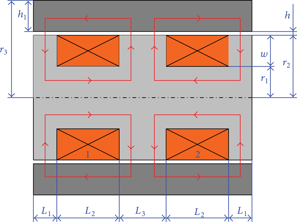
A magnetic flux is necessary to induce changes in the viscosity of the MR fluid. Hence the magnetic field applied to the MR fluid must be accurately predicted by analyzing the magnetic circuit, which serves as the “supply line” of magnetic flux to the fluid. The magnetic circuit of the double coil MR valve is shown in Figure 3. Because the structure of the double coil MR valve is distributed symmetrically, the length L3 was designed to be twice of the length L1, and the effects of the two exciting coils can be considered as one coil. As the iron permeability is higher than that of the air, the flux leakage can be neglected. The magnetic resistances of each segment are as follows.
The simplified magnetic circuit of the double coil MR valve.
The magnetic resistance of the central axis segment of the valve spool is given by

The magnetic resistance of the flank of the valve spool is defined as
The magnetic resistance of resistance gap is represented as

The magnetic resistance of valve body is defined as

where the constant μ0 is the vacuum permeability and μ is the permeability of the material of the valve spool and the valve body.
The total magnetic resistance is given by

According to Ohm's law for magnetic circuit, the magnetomotive force is represented as

where B0 is the magnetic flux density of resistance gap and S0 is the flux area of resistance gap.
2.3. Simulation Analysis Using FEM Method
Figure 4 shows the axisymmetric two-dimensional finite element model of the double coil MR valve using ANSYS/Emag software. The materials of the valve spool and valve body are both 10# steel; the permeability of the valve spool and valve body is defined by the B-H curve of 10# steel; the material of exciting coil is copper; its relative permeability is 1; the resistance gap is full of MR fluid; its permeability is defined by the B-H curve of MRF-J01 produced by the Chongqing Instrument Material Research Institute. The value of the current density in two exciting coils is equal and is set as 8 A/mm2.

Two-dimensional finite element model of the double coil MR valve.
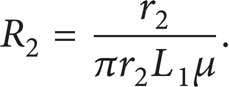
Figures 5 and 6 show the magnetic flux line distribution and the magnetic density contour under the applied currents of the same direction and the reverse direction, respectively. As shown in Figures 5 and 6, when the current directions of the two exciting coils are opposite to each other, the resistance gap is divided into three effective parts by magnetic field. Its magnetic intensity equals the sum of that in each coil, and the middle part has the highest magnetic flux intensity. However, if the two exciting coils have the same current, the magnetic flux density in the middle part will be zero.
Magnetic flux of the double coil MR valve.

Magnetic density contour of the double coil MR valve.
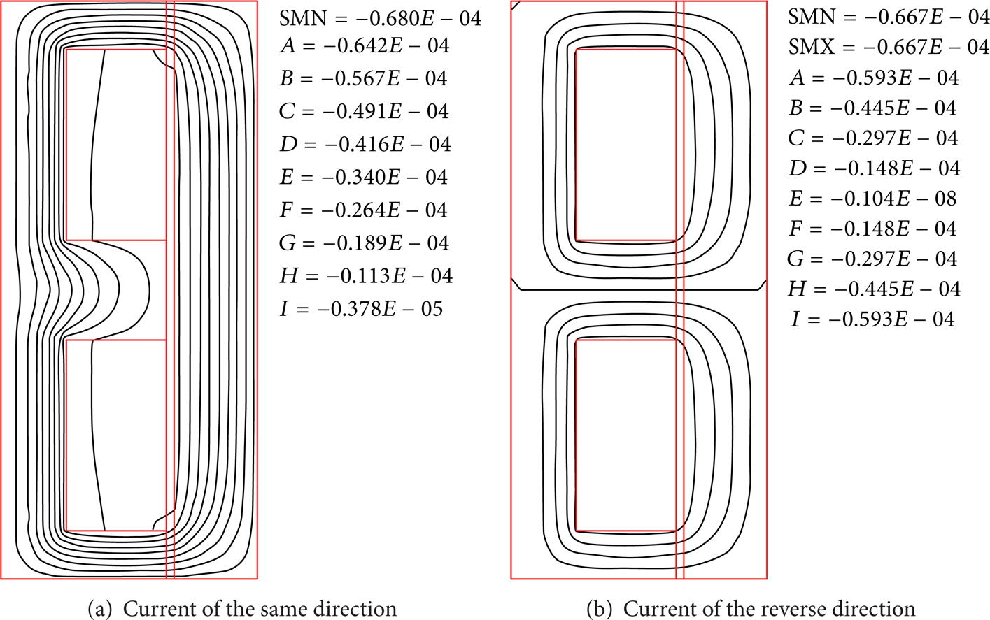
Figure 7 shows the magnetic flux density under two different current directions: one is the same direction currents applied to the two exciting coils, while the other is the opposite currents applied to the two exciting coils, and the current value of the two coils applied is 1.5 A, respectively. It can be seen that the magnetic flux densities reached a certain value in the three effective sections when the opposite currents were applied. However, the magnetic flux density in the middle parts was zero when the two exciting coils were applied to the same direction currents. Hence, the pressure regulating performance under the reverse direction currents is better than that of the same direction currents.
Magnetic flux density in the gap under different current directions.
Figure 8 shows the magnetic flux density under the reverse currents applied to the two exciting coils; current I1 is set as 1.5 A as shown in Figure 2; current I2 is set as 1.5 A, 0.8 A, and 0.4 A, respectively. As shown in Figure 8, the magnetic flux density is different in the middle part and the other end part. The reason is that the applied current I2 plays the role of the pressure regulating in each exciting coil.
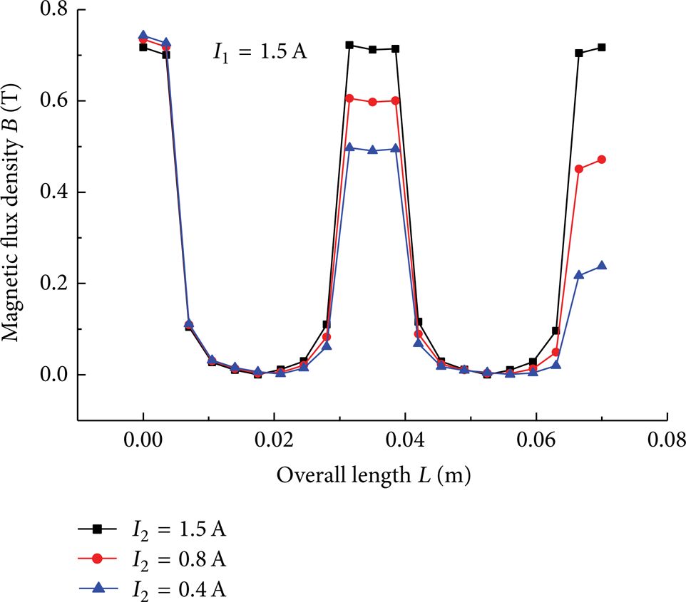
Magnetic flux density in the gap under different applied currents.
2.4. Prototyping of the Double Coil MR Valve
Figure 9 shows the prototyping of the proposed double coil MR valve, and Table 1 summarizes the primary valve parameters.
Primary parameters of the double coil MR valve.

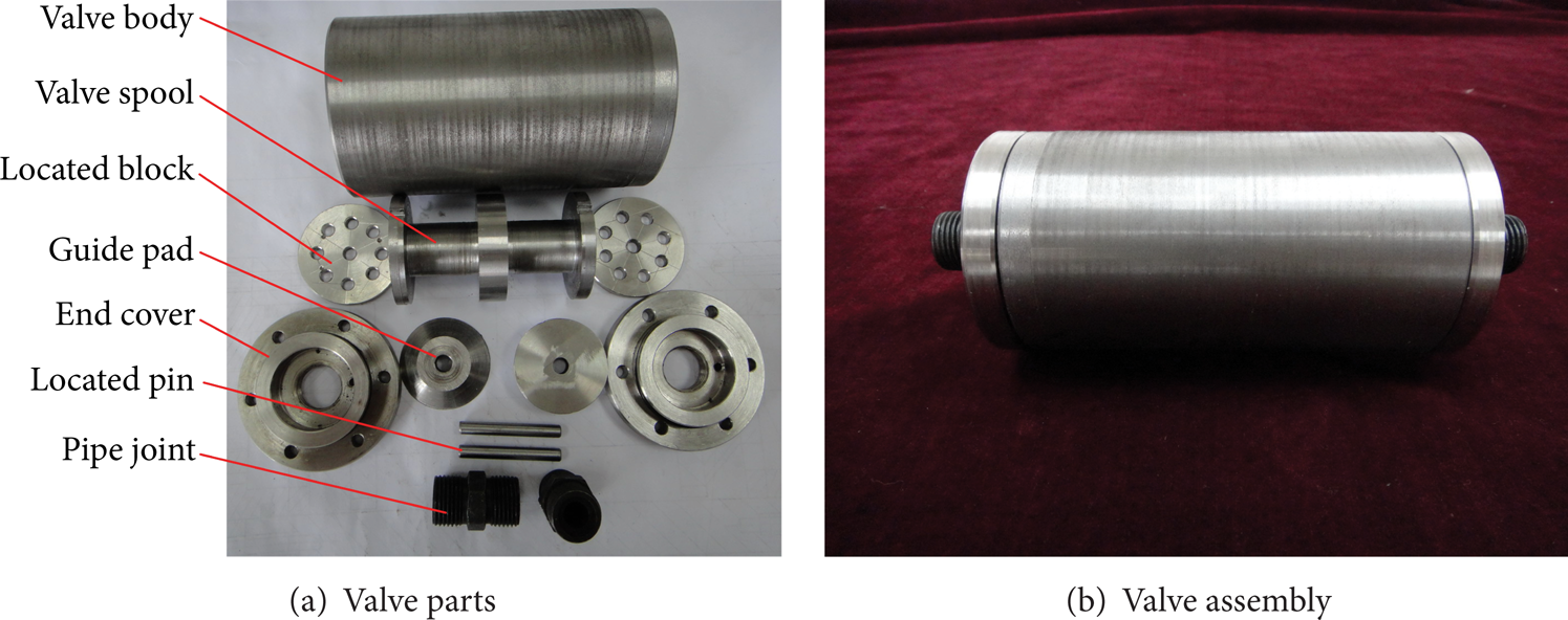
Photograph of the double coil MR valve.
3. Pressure Drop Analysis of the Double Coil MR Valve
3.1. Mathematic Modeling
Based on the analytical approach, the fluid passing through the MR valve includes the inlet and outlet fluid flow in the circular pipe, the inlet and outlet fluid flow in the thin-walled hole of the located block, and the annular fluid flow in the resistance gaps. So, the total pressure drop Δp developed in the double coil MR valve can be expressed as a sum of the pressure drops in various sections of the MR valve, which can be seen in Figure 10. The total pressure drop Δp is represented as

where Δp1 and Δp5 are the pressure drops corresponding to the Newtonian circular pipe fluid flow, Δp2 and Δp4 are the pressure drops corresponding to the Newtonian thin-walled hole fluid flow, and Δp3 is the pressure drop corresponding to the non-Newtonian annular fluid flow.
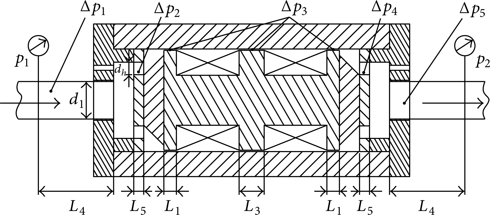
Fluid flow schematic of the proposed double coil MR valve.
The pressure drops Δp1 and Δp5 in the circular pipe flow can be expressed as

where q is the flow rate of the hydraulic system, η is the dynamic viscosity with no applied magnetic field, d1 is the inner diameter of the hydraulic pipe connected to the end cover, and L4 is the length between the outlet of the MR valve and the inlet of the pressure transducer.
The pressure drops Δp2 and Δp4 developed in the thin-walled hole of the located block are given by

where ρ is the MR fluid density, C q is the discharge coefficient, and dh is diameter of thin-walled hole of the located block. The discharge coefficient C q can be calculated as

where R e is Reynolds number of MR fluid flow.
In this study, the MR fluid passing through the double coil MR valve can be modeled as the Bingham plastic fluid:

where τ is the shear stresses, τ
y
(B) is the field-dependent yield stress, and
Figure 11(a) depicts the annular fluid flow resistance channel between the inner face of the valve body and the outer annular face of the valve spool with a radius of R. In general, the annular fluid flow resistance channel of the valve containing the MR fluid is modeled as an approximate flat parallel plate model containing the MR fluid. As shown in Figure 11(b), the width of the equivalent rectangular duct is 2πR, and R equals r2 + 0.5h; the length L of the equivalent rectangular duct equals 2L1 + 2L2 + L3 as shown in Figure 3; and the thickness h of the equivalent rectangular duct is the thickness of the annular flow resistance gap.
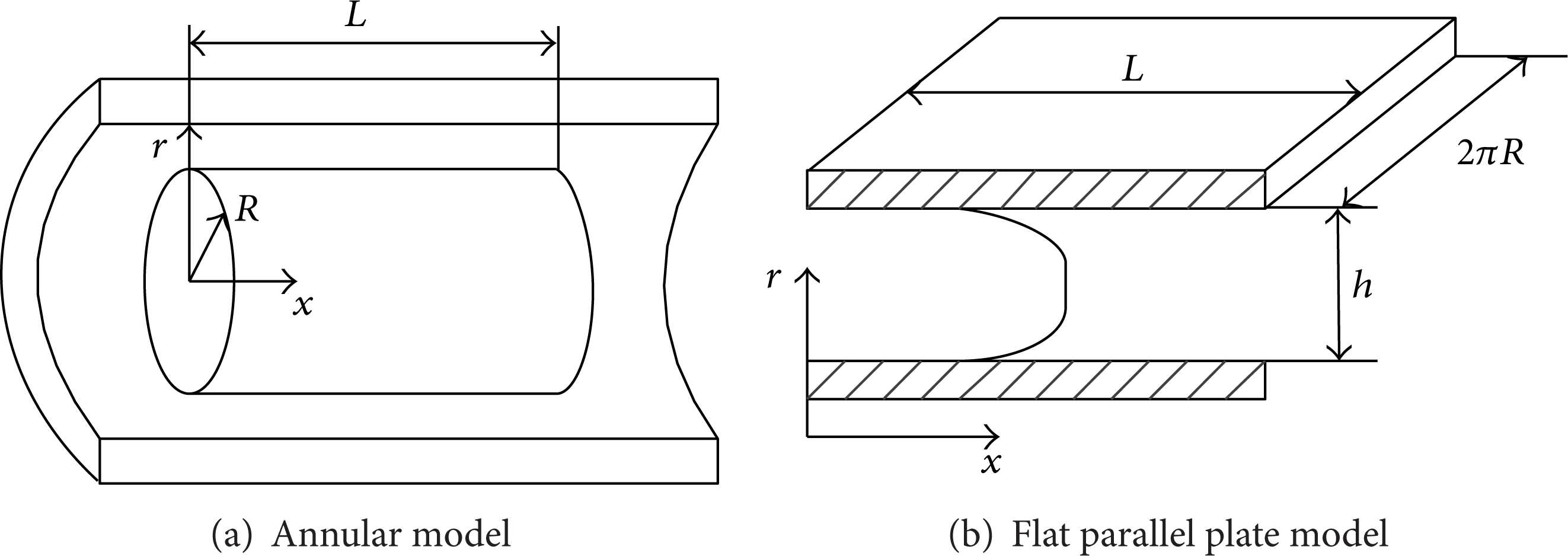
Modeling of the MR fluid flow in an annular flow resistance channel.
The pressure drop Δp3 produced in the resistance gaps is calculated by

where Δpτ and Δpη are the field-dependent and viscous pressure drop of the double coils MR valve, respectively.
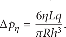
The viscous pressure drop Δpη can be calculated as
On the other hand, Δpτ is given by
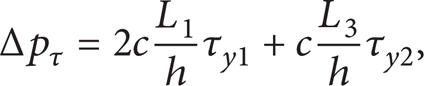
where τy1 and τy2 are the yield stresses of the MR fluid in the end ducts and the middle duct, respectively, and c is a coefficient which depends on the flow velocity profile and has a value ranging from a minimum value of 2.0 to a maximum value of 3.0.
From (12)–(14), the pressure drop Δp3 is expressed as
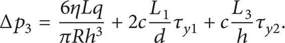
So, the total pressure drop Δp can be represented as

The selected pump in the hydraulic system is a fixed gear pump which has a constant flow rate q. It can be seen that the first three parts of (16) are constant too, so the pressure drop Δp is mainly dependent on the change of the yield stresses of the τy1 and τy2. As the yield stresses of the τy1 and τy2 are controlled by the applied currents I1 and I2, the pressure drop Δp can be controlled in real time by changing the values of the applied currents I1 and I2.
3.2. Experimental Setup for the Proposed Double Coil MR Valve
In order to validate the valve performance of the proposed double coil MR valve, an experimental test rig was built up and shown in Figure 12. The motor driven gear pump was used as a power unit. The pressure inducer (a) and the pressure inducer (b) were adopted to measure the inlet pressure and the outlet pressure of the double coil MR valve, respectively. The flow meter was applied to detect the flow rate of the hydraulic system. The relief valve (a) was used as a safety valve to protect the hydraulic system, while the relief valve (b) was used to simulate the different load cases. DC power supply (a) was used to supply the power for the two pressure transducers and the flowmeter, and DC power supply (b) was used to supply the power for the two exciting coils of the MR valve. The data acquisition board was used to acquire the data of the pressures and the flow rate of the system, and the host computer was used to real-time-monitor the relevant test parameters of the hydraulic system.
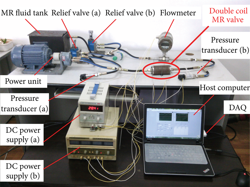
Experimental setup for the evaluation of the double coil MR valve.
3.3. Experimental Tests of Pressure Drop
In order to evaluate the pressure regulating effects of the double coil MR valve, the experiments were carried out to investigate the relationships among the pressure drop, the directions, and the values of the applied currents of the two exciting coils and the different load cases.
3.3.1. Pressure Drop under Continuously Applied Currents on the Double Exciting Coils
Figure 13 shows the pressure drop of the double coil MR valve under the continuously applied currents with the same direction and the reverse direction. It can be seen that both pressure drops increased with the increase of the applied currents of I1 and I2. The pressure drop under the same direction applied currents nearly equals that of the reverse direction applied currents when the applied currents are zero. However, the pressure drop reaches 1100 kPa when the reverse direction current is 1.8 A, while the pressure drop reaches only 550 kPa when the same direction current is 1.8 A. The reason is that the pressure drop only includes zero field viscous pressure when the applied current is zero, so the pressure drop between the two conditions is very close. When the applied currents I1 and I2 increased, the MRF that passed through the MR valve should overcome the field-dependent pressure drop, and this pressure drop increased with the increase of the magnetic flux density produced in the resistance gap. As shown in Figures 7 and 8, the magnetic flux densities were bigger in the middle part of the resistance gap under the reverse direction applied current than that of the same direction applied current, which leads to the pressure drop being bigger too.

Pressure drop under continuously applied currents I1 and I2 (I1 = I2).
3.3.2. Pressure Drop under Continuously Applied Current on One Exciting Coil While Another Exciting Coil's Applied Current Is Fixed
Figure 14 shows the pressure drop under the continuously applied current I1 and the fixed applied current I2, and Figure 15 shows the pressure drop under the continuously applied current I2 and the fixed applied current I1. As shown in both figures, the pressure drop increased with the increase of the applied currents I1 and I2, respectively, though the other exciting coil's applied current was fixed, and the maximum pressure drop also reached about 1100 kPa when the applied currents I1 and I2 are 1.8 A, respectively.

Pressure drop under continuously applied current I1 (I2 is fixed).

Pressure drop under continuously applied current I2 (I1 is fixed).
3.3.3. Pressure Drop under Different Load Cases
The relief valve (b) was applied in the experimental test rig to simulate the loading conditions in the hydraulic system, and three typical load cases were selected by adjusting the outside valve knob in this study. Load case 1 was denoted by adjusting the outside valve knob by one clockwise circle at the initial state; load case 2 was denoted by adjusting the outside valve knob by two clockwise circles at the initial state; and load case 3 was denoted by adjusting the outside valve knob by three clockwise circles at the initial state. Figure 16 shows the working pressure under the continuously applied currents I1 and I2 at load case 3. It can be seen that the inlet pressure p1 increased with the increase of the applied current, and the outlet pressure p2 remained in a certain value determined by the relief valve (b), so the pressure drop of the double coil MR valve also increased with the increase of the applied current, and its value ranges from an initial value of 150 kPa to a maximum value of 1100 kPa.
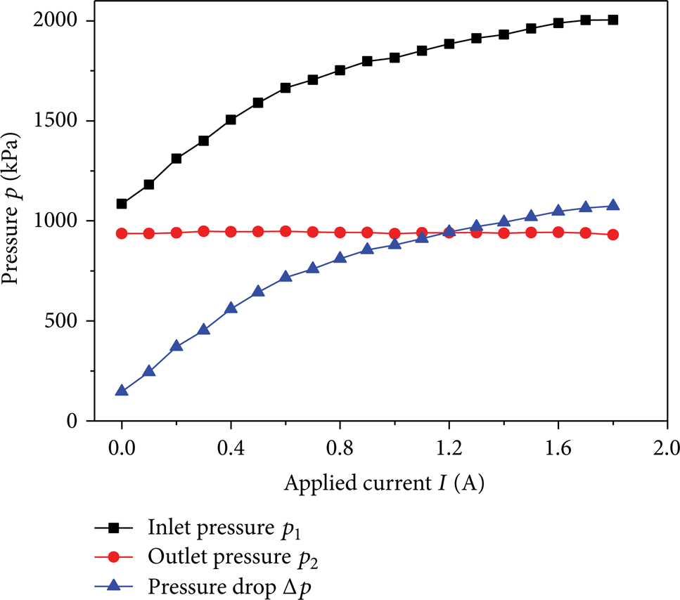
Pressure versus applied currents I1 and I2 at load case 3 (I1 = I2).
Figure 17 shows the pressure drop of the double coil MR valve at the three typical load cases. It can be seen that pressure drop remains at a certain value, which means the load cases do not influence the pressure drop. From the figure, it can be found that the maximum pressure drop can also reach 1100 kPa.
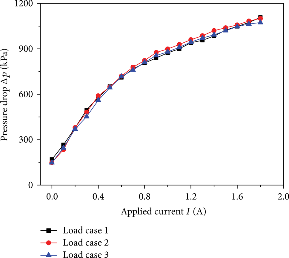
Pressure drop versus applied currents I1 and I2 at three typical load cases (I1 = I2).
4. Conclusions
In this work, the new proposed double coil MR valve with outer annular resistance gap provided a better valve performance through the finite element analysis, numerical simulations, and experimental test verifications. The maximum pressure drop can reach 1100 kPa by adjusting the applied currents of the two exciting coils, which exhibited a good pressure regulating ability in the hydraulic system.
Conflict of Interests
The authors declare that there is no conflict of interests regarding the publication of this paper.
Footnotes
Acknowledgments
This research was financially supported by the University of Wollongong UIC grant, the National Natural Science Foundation of China (no. 51165005), and the International Cooperation Project of Jiangxi Province of China (no. 20132BDH80001).