
Abstract
A novel magnetorheological (MR) damper with a multistage piston and independent input currents is designed and analyzed. The equivalent magnetic circuit model is investigated along with the relation between magnetic induction density in the working gap and input currents of the electromagnetic coils. Finite element method (FEM) is used to analyze the distribution of magnetic field through the MR fluid region. Considering the real situation, coupling equations are presented to analyze the electromagnetic-thermal-flow coupling problems. Software COMSOL is used to analyze the multiphysics, that is, electromagnetic, thermal dynamic, and fluid mechanic. A measurement index involving total damping force, dynamic range, and induction time needed for magnetic coil is put forward to evaluate the performance of the novel multistage MR damper. The simulation results show that it is promising for applications under high velocity and works better when more electromagnetic coils are applied with input currents separately. Besides, in order to reduce energy consumption, it is recommended to apply more electromagnetic coils with relative low currents based on the analysis of pressure drop along the annular gap.
1. Introduction
Magnetorheological fluid (MRF) is a kind of controllable or smart fluids whose rheological properties can be dramatically and reversibly varied by the application of an external magnetic field in milliseconds [1]. Generally, MR fluid behaves like an ordinary Newtonian fluid, when exposed to a magnetic field, and the metal particles are guided by the magnetic field to form a chain-like structure and it becomes a grease state. MR fluid technology has been investigated in or applied to a variety of shock and vibration isolation systems, such as shock absorbers, clutches, polishing devices, actuators [2], hydraulic valves, gun recoil systems [3, 4], railway vehicles [5, 6], military suspension systems [7–9], and seismic isolation systems for civil infrastructures [10, 11].
Magnetorheological dampers (MRDs) have been relatively successful in most of the shock and vibration mitigation system. For the low-speed applications, fortunately, the requirement for the damping force performances of the MR damper is less demanding. The traditional MR dampers with annular gap [12] or utilizing bypass valves [11, 13, 14] could provide a reasonable performance for the semiactive control systems. However, the dynamic range of the conventional MR dampers, which is often defined by the ratio of field-on to field-off damper force, decreases significantly with increasing piston speed (v>3 m/s) due to the increase of the viscous damping force (i.e., field-off damper force) [15]. In order to meet the requirements of the dynamic force range, Mao et al. [16] proposed and experimentally tested an MR damper with bifold valves. Bai et al. [15] proposed a biannular-gap MRD with an inner-set permanent magnet to decrease the baseline damper force (i.e., the negative current case for the biannular-gap MRD) at high speed while keeping the appropriate dynamic force range for improving shock and vibration mitigation performance. Becnel et al. [17] designed and tested an MR damper to control both the shock and loads and vibration for crew seat of an EFV. Their investigation results indicate that the maximum damping force and dynamic range at high velocity can be improved to some extent by changing the dimensions. However, for applications with higher speed, more investigations on MR fluid flow exposed to external magnetic field are needed to design high efficient MRDs, which can provide maximum dynamic range as well as large damping force.
In the impact buffer system, MR dampers have shown promising advantages in replacing the conventional hydraulic absorbers [7, 8, 18]. Due to the controllable forces provided by MR technologies, the lighter weapons could be designed with increasing firing power and more mission flexibility [19, 20]. However, most researches on MR fluids or devices subjected to impact loadings are focused on their behaviors. Little work has been done considering the multiphysics coupling in MR damper, which in fact is a highly nonlinear multidisciplinary problem with coupling from electromagnetic, flow mechanism, thermal dynamic, structural force, and so on. Particularly, optimal design and control of MR devices based on multiphysics turn out to be more challenging.
This research aims to analyze a novel MR damper with multicoil configuration which works under firing impact loading conditions. Through theoretical analysis of the multiphysics in MR damper, coupling equations are presented to describe the real situation. Then, the novel MR damper with multistage coil is designed and manufactured in order to obtain the optimal results of larger damping force, higher dynamic range, and less induction time needed for magnetic coil. Finally, by comparing the proposed measurement index, the simulation results show that the novel damper is promising for applications under impact loading and high shear rate and it works better when multiple coils are applied with input currents. Besides, in order to reduce the total energy consumption, it is recommended to apply multiple coils with relative low current and reasonable control strategy enabling the impact force buffered in a more smooth and steady way.
2. A Novel Magnetorheological Damper
Figure 1 displays the schematic and a photograph of the novel MR damper. The number of turns of each coil is 500 with 0.69 mm diameter copper wire. The enameled wires come from the wire-leaded hole 3 and wind around the groove to form four parallel magnetic circuits. There are four wire-leaded holes inside the piston, so each coil can be applied with input current separately. Thus, the magnetic field route is composed of the cylinder, working gap, and piston head. To make sure the magnetic flied lines go along the expected route, the piston rod and guide head connecting the piston head are made of aluminum and copper, respectively. The basic specifications of the novel MR damper are shown in Table 1.
Main parameters of the novel MR damper.


Novel MR damper: (a) schematic of the designed damper; (b) photograph of the designed damper.
When currents are applied to the coils of the MR damper, the induced electromagnetic will provide damping force to hinder the reciprocating movement of piston. By adjusting the number of working coils as well as value of input current or together, the MR damper can produce controllable damping force. For the situation with no current on, the MR damper acts as a conventional viscous damper.
3. Magnetic Circuit of the Novel MR Damper
For conventional MR dampers based on mixed or flow mode, the magnetic fields generated by electromagnetic coils which wind around the piston are distributed through the working gap and perpendicular to the direction of MR fluid flow. Obviously, the novel MR damper with multicoil configuration increases the active length of damping channel to some extent.
Since the four coils can be applied with current separately, this configuration exhibits an advantage that the induction time needed for the magnetic coil is much less [21]. Therefore, for a limited time, the control strategy plays a greater role on the damping force, which is mainly under the control of applied magnetic field.
3.1. Material Selection
In general, the maximum force available in an MR damper is limited by the magnetic saturation in the effective area. Another important parameter for the selected materials is the permeability. Thus, when designing MR dampers, it is desirable to choose magnetic materials with high magnetic saturation limit but avoid exceeding the saturation limits in the preliminary design stage. In this study, the piston head and cylinder are made of 45 number steel. The B-H relation of 45 number steel is shown in Figure 2, and the magnetic saturation of 45 number steel occurs at the magnetic field density, B, 1.7 T.
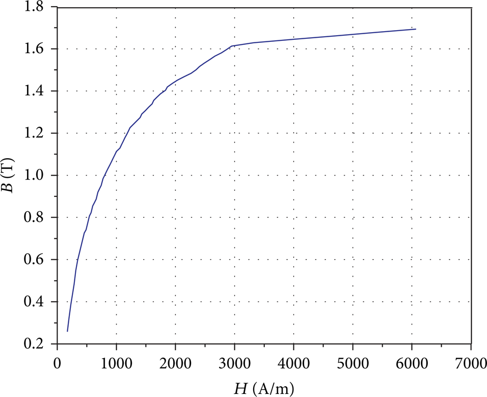
B-H relationship of 45 number steel.
In selecting the working fluid, the MR fluid with low “zero-field” viscosity is preferred as it lowers the viscous damper force, which will widen the overall dynamic range. Yield stress is another important parameter to increase the total damper force and large dynamic range as well. Here, we select SG-MRF2035 (provided by China Ningbo Shangong Center of Structure Monitoring and Control Engineering Co., Ltd.) because it exhibits high yield stress (45 kPa) at the saturation point (0.9 T) of magnetic induction density. The density and initial apparent viscosity (30°C, 500's−1) of the chosen MR fluid are 3090 (kg/m3), 240 mPa·s, respectively. The operating temperature of the MR fluid ranges from −40 to 150°C and τ y -B relationship is shown in Figure 3.
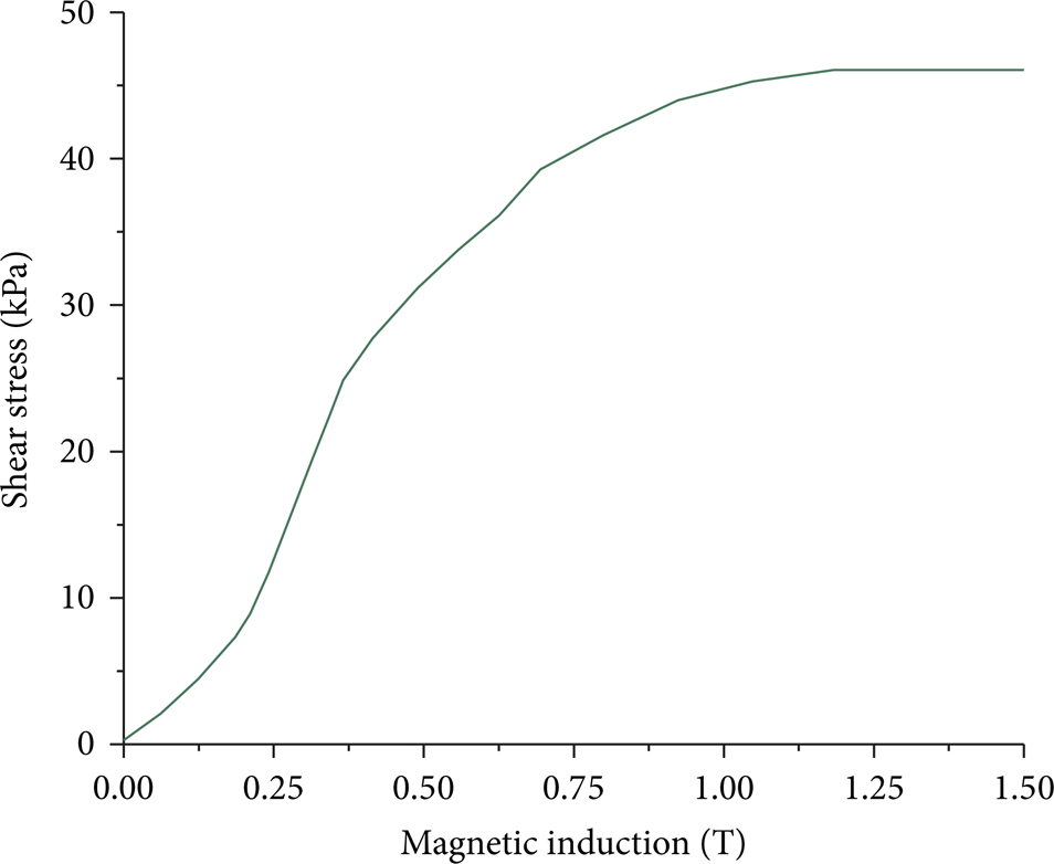
Shear stress versus magnetic induction (MRF2035).
3.2. Magnetic Circuit Analysis
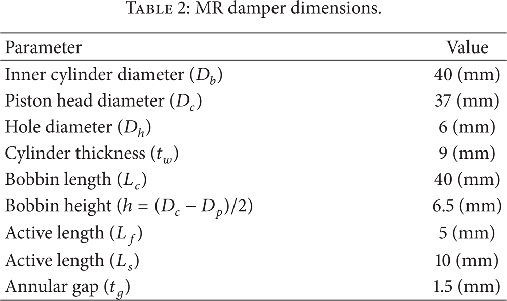
A magnetic field analysis is performed to ensure that the design satisfies the magnetic saturation constraint and that the magnetic flux perpendicularly passes through the MR fluid. Moreover, the key design parameters can be selected and validated based on the magnetic field analysis. Figure 4(a) shows the cross-sectional diagram of the multistage MR damper, the detail dimensions of which are shown in Table 2. An equivalent magnetic circuit is shown in Figure 4(b) and the magnetic reluctance in the equivalent magnetic circuit can be expressed as

MR damper dimensions.

Multistage MR damper.
In order to decrease the magnetic coupling effect in the magnetic poles between two adjacent coils, the shared active length of the poles should be longer. So, the magnetic reluctances in the shared parts between two coils are therefore different. Rm1′, Rm2′, Rm3′, and Rm4′ are given by
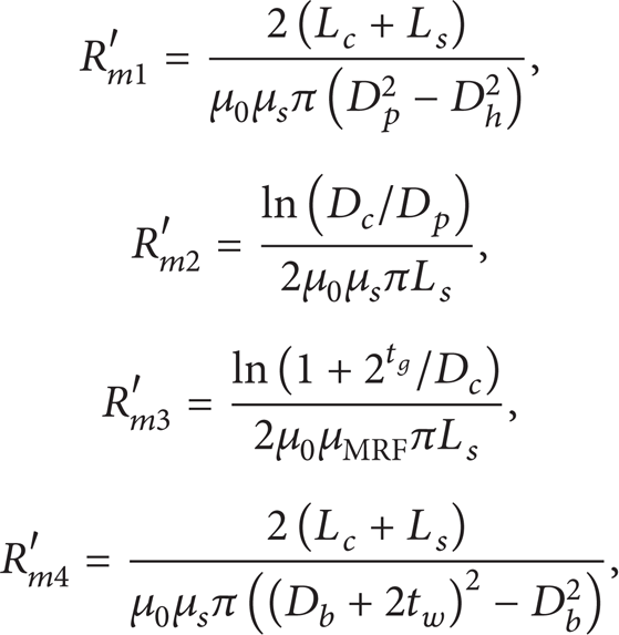
where μ0 is the magnetic permeability of vacuum; μ s and μMRF are the relative magnetic permeability of the solid materials and the MR fluid, respectively. And tg is the width of MR working gap; tw is the thickness of outer cylinder; L s and L f are the active lengths in the annular gap; D b , D c , and D h are the diameters of inner cylinder, piston head, and hole.
The magnetomotive force F derived from the magnetic circuit Kirchhoff's second law is given by
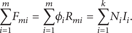
In the formulas, magnetic flux
According to the equivalent magnetic circuit, corresponding expressions in different magnetic circuits are obtained based on the formulas of Kirchhoff's law:

where ϑ1, ϑ2, ϑ3, ϑ4, ϑ1′, ϑ2′, and ϑ3′ are the magnetic flux values in the respective locations. Assuming that the magnetic field is uniform and perpendicular to the MR fluid section S, the magnetic field density can be expressed as
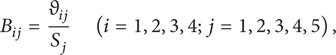
where i represents the number of magnetic coils and j is the number of active working gaps. If the relative permeabilities (μ s and μMRF) are treated as constant, the magnetic field densities in the MR fluid sections can be determined by using (1)–(5).
However, the magnetic characteristics of the solid materials and MR fluid are highly nonlinear; it is difficult to obtain the precise magnetic field from the calculation of above equations. So, a magnetic circuit analysis using finite element code is shown in the subsequent section.
3.3. FEM Analysis
The magnetic circuit of the damper is analyzed by COMSOL Multiphysics. According to the axial symmetry, analysis for the three-dimensional magnetic circuit is reduced to a two-dimensional 1/2-axisymmetric model. Figure 5 shows the magnetic flux density and distribution of magnetic field lines when only one coil is applied with input current. Obviously, the distribution of magnetic field lines covers the whole cross-section; however, the magnetic field distributions of coil I and coil II are totally different.
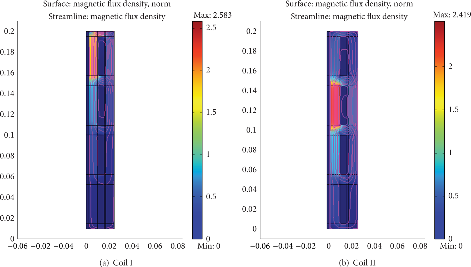
Magnetic flux density and distribution of magnetic field lines.
Figure 6(a) shows the magnetic field density along the middle of the working fluid gap by applying the first coil with current (1.5 A) and the case of the second coil applied with current (1.5 A) is shown in Figure 6(b).

Magnetic flux density in the annular gap.
When coil I is applied with current (1.5 A), the maximum magnetic field density reaches 0.97 T in the first active length and it decreases exponentially along the annular gap. However, in case of coil II, the magnetic field density along the working gap behaves more uniform, followed by 0.29 T, 0.42 T, 0.35 T, 0.16 T, and 0.1 T, respectively.
From (4), we know that the magnetic flux satisfied certain distribution rule in the parallel magnetic circuit. The y-axis in Figure 7 indicates the ratio between each magnetic flux density along the active annular gap and the maximum magnetic flux density when coil I and coil II are applied with varying currents (0.25 A–2.5 A) independently. The magnetic field intensity in the working gap rises proportionally when the input current increases and the internal relations among the five active regions can be regarded as a fixed linearity.

Ratio of magnetic flux density along the annular gap.
Based on the distribution of magnetic field density, the others in the working gap can be expressed as.
Coil I
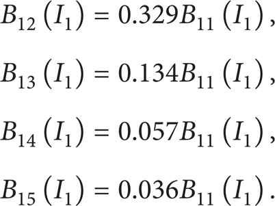
Coil II

where B ij means the inductive magnetic field density in the jth active working gap when the ith coil is applied with input current.
Besides, from Figure 8, the numerical solution of the relation between the magnetic field density in the first working gap and input current (I1) in the first coil can be obtained as
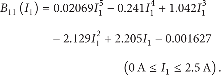
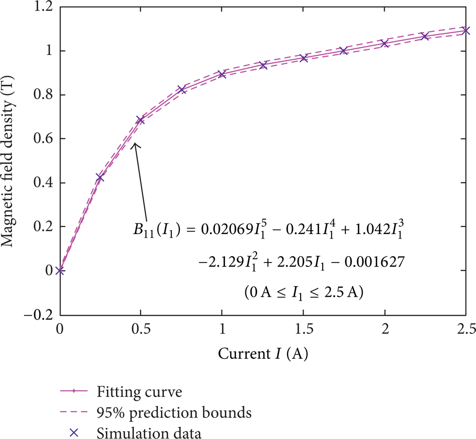
Magnetic field density B11(I1) fitting.
Similarly, when only the second coil is applied with input current (I2), the fitting formula of the magnetic field density in the second working gap can be expressed as (Figure 9)


Magnetic field density B22(I2) fitting.
Due to the structural symmetry of piston head, when applied with the same input current, the magnetic fields provided by coil I and coil IV (coil II and coil III) also show symmetrical distribution. In order to enhance the magnetic field density in the working gap effectively, the current direction of adjacent coils should be opposite. When the four coils are applied with current independently at the same time, the magnetic field density

According to the symmetric distribution of magnetic field, the substitution of (6)–(9) into (10) gives

4. Multiphysics Theoretical Analysis
As the piston head moves back and forth inside the damper cylinder, the fluid is forced to pass through the annular channel with large shear rate, causing significant heat generation. The heat is transferred in both the axial and radial directions. In the radial direction, the heat is conducted through the cylinder house wall and converted to the air outside the damper. Meanwhile, the MR fluid is forced to flow through the annular gap under high pressure and slowed down by the magnetic field due to MR effect. In this study, a commercial CFD package was used to verify MR fluid flowing in this complex situation with heat transfer, electromagnetic induction, and high shear rate.
4.1. Thermal Analysis
The heat in the MR damper is mainly generated by two parts, one is from self-inductance of the electromagnetic coil with fast-changing current, and the other comes from the friction of the relative motion between the piston and the cylinder. Therefore, it can be expressed as

where X(t) is a sinusoidal input displacement, I is the input electric current, and R is the wire resistance of the electromagnet. W(t) represents the work input to the system through reciprocation of the piston rod. For this analysis, however, the input current applied to the damper is regarded as constant for simplicity. The nonlinear constitutive law for the MR fluid damper is assumed to be as

where C is the damping coefficient and α is a fractional exponent that accounts for the nonlinearity in the MR fluid damper. It should be noted that both C and α are functions of input current I and temperature T. Generally, the range of α is 0<α<1. A value of one represents purely viscous behavior and a value of zero corresponds to purely rigid plastic behavior.
Meanwihle, there exists a heat exchange between the magnetic shell and the ambient, and the exchange power P a is expressed as

where h is the convection heat transfer coefficient, A s is the outer surface area of the damper, T(t) is the surface temperature of the damper at any given time, and T0 is the ambient temperature.
Considering the energy balance, the energy consumption leads to rising temperature besides emission to the outside. The energy balance yields

where
4.2. Force Analysis
The MR damping relies on the enlargement of shear stress for vibration control. In an applied magnetic field, the MR fluid presents Bingham fluid properties with high viscosity and low liquidity; the constitutive equation can be expressed by

where τ is the shear stress of the MR fluid, τ0 is the magnetic shear stress, which is the function of the magnetic field,
Temperature effect on the performance of the MR fluid damper is mainly based on the change of the MR fluid's viscosity and the apparent viscosity presents a nonlinear decline when the temperature goes up [21]. Its characteristics meet the hydraulic oil viscosity-temperature relationship. That is,

where η T and η To are the oil viscosities when the temperature reaches T and T0, respectively; λ is the oil viscosity-temperature coefficient. Considering the temperature effect on the oil viscosity, η T is introduced into the dynamic model as a function of temperature. Based on (16) and (17), the pressure drop calculation model [22, 23] on both ends can be rewritten by

Accordingly, the damping force can be replaced by
where L is the damping channel length; Q is the flow rate through the channel; and D is the piston head diameter; d, h, and v are the piston rod diameter, working gap width, and velocity, respectively. The former item describes viscous damping associated with the speed and the latter indicates Coulomb damping.
4.3. Fluid Analysis
The description of yield stress leads to complications in numerical simulation, due to its nondifferentiability in the postyielding regions of the MR fluid. However, one approach to the nondifferentiability problem is first to determine the bounds of the postyielding regions and then to treat them as “plug flow” (a region in which the velocity is constant). But this approach assumes fully developed flow and becomes far more complicated when dealing with complex channel geometries [24]. Another approach employs a commercial finite element software package and follows a close approximation of the Bingham plastic behavior, proposed by Case et al. [25]. Thus, in this model, the Navier-Stokes equations are used to describe the fluid motion, assuming fluid incompressibility and the apparent viscosity subject to

Substituting (17) into (20), we can rearrange the apparent viscosity
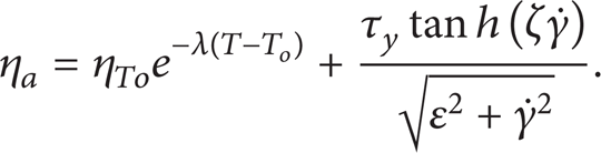
It can be seen that the MR fluid is modeled in the typical manner for non-Newtonian fluids with variable viscosity which takes temperature effect into consideration during the long-stoke damping. ε is a small constant which eliminates the discontinuity and ζ is a scaling term for the slope.
5. Electromagnetic-Flow-Thermal Coupling Analysis
5.1. Simulation Description
In the whole process of simulation, it experiences much exchange of information among the multiple physics. Both the apparent viscosity and flow field of MR fluid change according to external magnetic field. On the other hand, the energy transmission and consumption inside the damper influence the MR fluid flow as well.
For the present long-stroke damper, coupled with electromagnetic, thermal dynamic, and fluid mechanism, the process of the piston's moving inside the cylinder was simulated by the software COMSOL Multiphysics. In order to simplify the model and improve its accuracy, the dynamic model assembled for this project uses 2D axisymmetric space. No-slip wall boundary conditions are applied for both ends of the damper cylinder and on the inner wall of the damper cylinder house. Moving wall with the given velocity is applied on the boundaries of the piston head and on the piston rod. The conjugate heat transfer is solved in the field domain and the damper cylinder house wall: heat transfer by convection and conduction in the fluid domain heat transfer by conduction only by the solid domain and the temperature field is continuous between the fluid and solid domain. The heat flux boundary condition based on the Newton's cooling law is applied on the outside boundaries of the cylinder house wall. The ends of the damper connected to the structures outside are kept at constant temperature.
The motion is modeled using the arbitrary Lagrangian-Eulerian (ALE) deformed mesh. The ALE handles the dynamics of the deforming geometry and the moving boundaries with a moving grid. The Navier-Stoke equation for fluid flow and heat equation for temperature variation are formulated in these moving coordinates.
5.2. Results and Discussion
The four-stage coils are designed to apply current independently and the directions of adjacent input current are kept opposite to enhance the damping force. Figure 10 shows the symmetrical geometry model of the four-stage MR damper. In order to simplify the FEM simulation, the input currents are fixed without any control strategies. The model of the four-stage MR damper is established to analyze the process of electromagnetic field, flow field, and thermal field on the basis of sequential coupling method, the results of which are to be shown in the following sections. In this simulation, the motion of the piston head is specified by a sine wave function of 0.4 Hz and displacement of 300 mm. The constants (ζ, ε, and λ) were specified as 0.3, 0.002, and 0.0169, respectively.

Symmetrical model of multistage damper.
5.2.1. Results of Thermal Analysis
Figure 11 shows a sine-wave rise of the temperature within two cycles except some discontinuity points. The case when all the coils are applied with current shows a relative high temperature compared with the other cases. Meanwhile, temperature at the piston head (R = 18.5 mm, Z = 95 mm) increases as the input current rises from 0.5 to 1.5 A, the maximum of which reaches 37 and 39°C respectively, except for the discontinuity points. However, the majority of the temperature rise is caused by the friction in the MR damper rather than from the electromagnetic coils.

Temperature at the piston head (R = 18.5 mm, Z = 95 mm).
As we can see from Figure 12(a), the fluid region (cross-section Z = −115 mm) involved with temperature-rising extends as the piston moves forward and Figure 12(b) shows that the temperature in the case of coil2 rises higher than the case of coil4 when they are applied with the same current. Due to the instantaneous friction between the cylinder and the main piston, the temperature appears to be an exponential rising in the working gap. Figure 13 shows the coupled results of fluid flow and temperature in two cycles with varying input current and the temperature increases rapidly in the first 0.125's and slows down in the next cycle (T = 1.25's).

Temperature in the MR fluid cross-section (Z = −115 mm) (a) coil4 with 1.5 A and (b) t = 0.25's, I = 1.5 A.

Temperature field coupled with flow field in two cycles (coil2).
5.2.2. Results of Flow Field Analysis
Due to MR effect, behaviors of the MR fluid being active in the annular gap act like a rigid body below the dynamic yield stress.
So, the fluid flow slows down above the magnetic poles when the MR fluid is forced to pass through the working gap and the velocity drops above the magnetic pole become larger when more electromagnetic coils are applied with input current (Figures 14(a) and 14(b)). However, MR fluid in the nonactive area has a relative higher velocity because of less external magnetic field. As (16) shows that the piston X(t) is a sinusoidal input displacement, the velocity in the working gap changes sinusoidally. When only coil4 is applied with current (1.5 A), the maximum velocities in the gap reach 16.25 m/s, 5.0 m/s, and 13.25 m/s as the time increases from 0.625's to 1.125's by step 0.25's (Figure 14(a)).

Velocity in the working gap (a) coil4 with 1.5 A and (b) velocity in the active region (t = 1.125's).
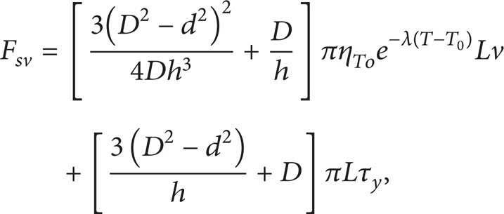
Obviously, the pressure drop caused by MR effect increases when four electromagnetic coils are applied with input currents. The total pressure drop developed in four-stage axial flow is apparently equal to the sum of that produced in each section, given by

So, the damping force triggered by piston rod movement is given by

where A p is the effective area of the piston head. Due to the single-rod damper, the effective area A p is different as the piston moves back and forth in one cycle and it can be given by
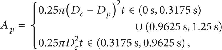
where D c is the cross area of the piston head and D p is the cross area of the piston rod.
From Figures 15 and 16, we conclude that the pressure drop is mainly produced in the annular gap and its peak value is dominated by the input current. The maximum damping force reaches 17000 N at 0.625's when all the coils are applied with input current (1.5 A). In addition, the rheological behavior of MR fluid is easily controlled by the input currents. Figure 17 shows the radial flow field at z = −115 mm (t = 1.125's). As we can see, the peak velocity decreases from 4.8 m/s to 3.2 m/s when the number of coils applied with current increases to four and the second peak velocity is accelerated by the MR fluid that comes from the left chamber.
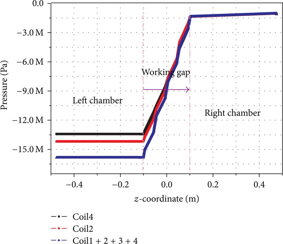
Pressure drop in the chamber (t = 1.125's, I = 1.5 A).

Damping force in one cycle (I = 1.5 A).
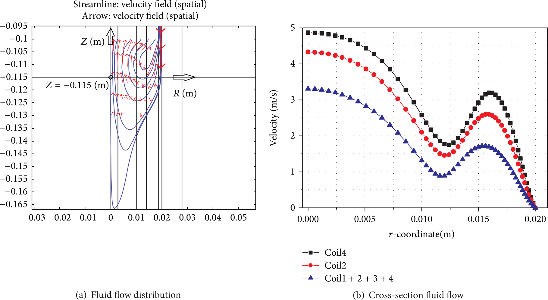
Radial velocity (Z = −115 mm, t = 1.125's).
5.3. Finding Objective
The constitutive model of MR fluid is often represented as the Bingham plastic due to its simplicity. Based on the constitutive model, the coupling physical parameters involving fluid features (such as yield stress, apparent viscosity, and flow index), structure parameters (annular gap width and active length), and the velocity of piston rod can be theoretically constructed. Among those, the yield stress is also a function of input current except for temperature.
The main performance parameters of novel MR damper are its maximum damper force, dynamic range, and inductive time needed for magnetic coil. For comprehensive consideration, a new measurement index involving the total damping force, dynamic range, and induction time needed for magnetic coil was presented as follows:

where α, β, and γ are the scale factors; F t , D t , and τ t are the target damper force, dynamic range, and time constant; X is the constraints of geometric dimensions; B max is the maximum induction magnetic field intensity in the gap; N is the number of the wire winding turns; and P1 is the ratio of lost power.
The objective in (25) is a crucial parameter to evaluate the performance of the novel multistage damper. The way of magnet input coils connected in parallel responds faster than that connected in series [26]. The average inductive time for the respective magnetic coil is about 16.5 ms and could be lowered to 10 ms by adding a correction circuit [27]. However, the dynamic range changes as the piston moves sinusoidally (Figure 18) and it rises promptly to about 10 when the Coulomb force dominates the fluid flow. Furthermore, from Figure 19, we can see that the multistage damper behaves unstably when single coil is working and it works better when more electromagnetic coils are applied with input currents.

Dynamic range (T = 1.25's).
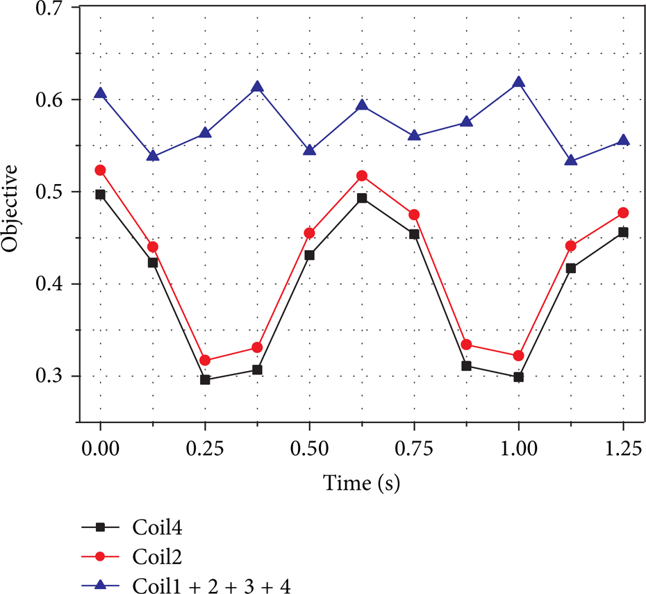
Objective (α = 0.5,β = 0.3,γ = 0.2).
Besides, the electromagnetic coils, being independent of current input, enable to apply different values of current at the same time. Thus, the pressure drop caused by MR effect in the long damping channel will be different between adjacent active regions. Figure 20 shows six different kinds of current inputs; here are some introductions of corresponding phenomenon.

Pressure drop in the damping channel.
Case 1 (I1 = I2 = I3 = I4 = 0.5 A). The produced pressure drop looks like saddle-shaped in the long damping channel with the lowest occurs in the inlet and outlet of working channel.
Case 2 (I1 = I4 = 0.7 A,I2 = I3 = 0.3 A). It is also saddle-shaped, but the lowest pressure drop occurs in the middle of the channel.
Case 3 (I1 = I4 = 0.3 A,I2 = I3 = 0.7 A). It behaves like a downward parabola.
Case 4 (I1 = 0.3 A,I2 = 0.4 A,I3 = 0.6 A,I4 = 0.7 A). Increasing current along the working channel produces stepwise pressure drop with the highest one in the fourth active region.
Case 5 (I1 = 2 A,I2 = I3 = I4 = 0 A). The pressure drop along the working gap decreases progressively.
Case 6 (I2 = 2 A,I1 = I3 = I4 = 0 A). There is a peak value in the second active region.
All the above cases affect the fluid flow through the long damping channel during the whole process which will be validated by experiments in the future work.
The total pressure drop ∑ΔPτ in Figure 21 shows that Case 5 and Case 6 only reach 900 kPa and 1800 kPa, respectively, which is much less than other cases. However, the corresponding power consumption accounts for a much larger percentage. In order to reduce the energy consumption, it is recommended to apply more electromagnetic coils with relative low current and reasonable control strategy enabling the impact force to buffer in a more smooth and steady way.
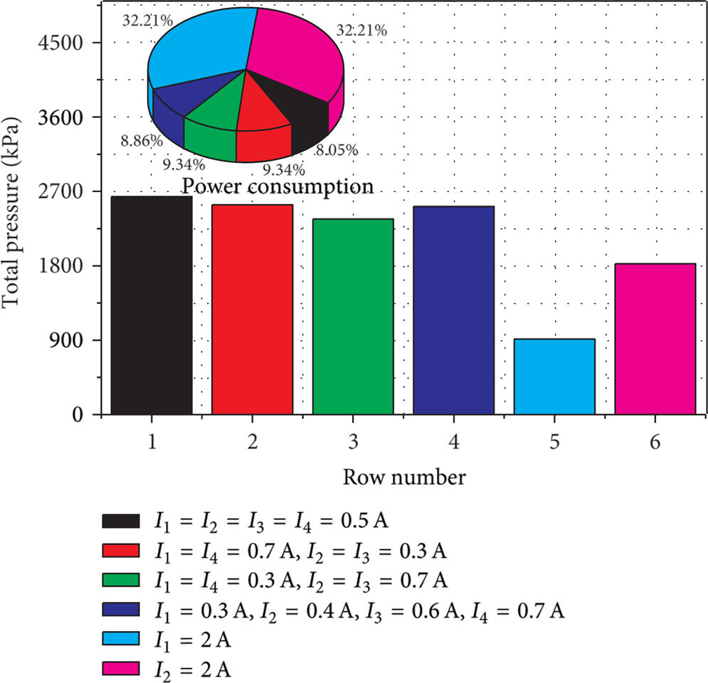
Comparison of pressure drop and power consumption.
6. Summary
A novel type of MR damper which has four coils and can be applied with current separately was proposed in this work. Considering the complex condition it works for, the multiphysics of the novel MR damper was theoretically analyzed and carried out by software COMSOL, including electromagnetic, thermal dynamic, and flow mechanism.
For electromagnetic analysis, the equivalent magnetic circuit model is investigated along with the relation between the magnetic induction density in the working gap and the input currents of the electromagnetic coils. The magnetic induction densities of the five active regions, being functions of input currents only, were obtained by FEM analysis as shown in (11). Applied with the same current in one coil (e.g., coil2 or coil3), it was found that the distribution of magnetic field is being symmetrical. The magnetic induction density in the working gap would be enhanced by applying currents with opposite direction in the adjacent coils. Otherwise, the damping force shows little increase no matter how much currents are applied.
For thermal analysis, the heat is transferred in both the solid and the fluid domains and generated from self-inductance of the electromagnetic coil with fast-changing current and friction of the relative motion between the piston and the cylinder. However, the majority of the temperature rise is caused by the friction inside the MR damper rather than self-induction from electromagnetic coils and the maximum temperature occurs in the piston head around the coils. The temperature appears to be an exponential rising in the working gap at the beginning but slows down when the maximum temperature reaches about 45°C due to low thermal conductivity of MR fluid.
For flow field analysis, the reciprocating motion of the piston has been implemented by using CFD analysis with deformed mesh. In addition, flow field (flow velocity, pressure, dynamic viscosity, etc.) at any position inside MR damper has been obtained. A modified Bingham plastic model as shown in (21) was proposed to model the flow of non-Newtonian fluid. The results show that the pressure drop between left and right chamber rises dramatically when magnetic field is applied.
Besides, a new measurement index involving the total damping force, dynamic range, and induction time needed for magnetic coil was proposed to evaluate the performance of multistage MR damper and the results show that it performs better when working coils increase. For reducing the energy consumption, it is recommended to apply more electromagnetic coils with relative low current and reasonable control strategy to enable the impact force to buffer in a more stable way which will be done in the future work.
Conflict of Interests
The authors declare that there is no conflict of interests regarding the publication of this paper.
Footnotes
Acknowledgments
This work was supported by the Natural Science Foundation of China (NSFC) Grant funded by the Chinese Government (no. 51175265 and no. 51305207).