
Abstract
The lunar rover design is the key problem of planet exploration. It is extraordinarily important for researchers to fully understand the lunar terrain and propose the reasonable lunar rover. In this paper, one new type of walking wheel modeled on impeller is presented based on vehicle terramechanics. The passive earth pressure of soil mechanics put forward by C. A. Coulomb is employed to obtain the wheel traction force. Some kinematics simulations are conducted for lunar rover model. Besides, this paper presents how to model lunar landing terrain containing typical statistic characteristic including craters and boulders; then, the second step is to construct basal lunar surface by using Brown Fractal Motion and the next is to add craters and boulders by means of known diameter algorithm and Random-create Diameter Algorithm. By means of importing 2D plain of lunar surface into UG, 3D parasolid is modeled and finally imported to ADAMS, which is available for lunar rover kinematics and dynamics simulation. Lastly, based on power spectrum curve of lunar terrain, the spectral characteristic of three different lunar terrain roughness is educed by using reverse engineering algorithm. Simulation results demonstrated the frequency of vibration mechanics properties of different roughness surfaces.
1. Introduction
In the planet exploration activities in future, people hope that planet vehicles can freely run in more complex and rugged environment so that we can do further research. So it can reveal the origin of the universe, development, and changes of the solar system, and also it is related to the lunar regolith energy utilization and other scientific engineering problems. The lunar rover named Lunakhod was launched by the former Soviet Union in the 1970s. These rovers whose names are “Sojourner” (Sojourner), “Spirit” (Spirit), and “Opportunity” (Opportunity) are launched by the United States in 1997 and 2003. All of them have demonstrated the world that the unmanned mobile robot have played the important role in the planetary [1, 2]. The second phase of China's “Chang E” lunar exploration is expected to launch a lunar rover for lunar exploration survey in 2013. It will collect lunar soil samples and return to Earth around 2017. The planet vehicle is an integral part of the planet detection medium and one of the biggest bright spot, and many research institutes have carried out relevant research work [3].
Sojourner, Spirit, and Opportunity Mars rover which belonged to NASA have made great achievements, expanding the cognitive level of human about Mars. In the future, the exploration mission of planet (such as MSL, ExoMars, “Chang E,” and SELENE) requires that planet vehicle operates autonomously in a more challenging soft rugged terrain. Lunakhod-1 is the first unmanned rover that successfully landed on the moon [4]. Its wheels use the structure that contain mesh rim, spokes, and tilt grouser. Its open-plan layout is conducive to clear the lunar regolith which is attached to the wheel and enhances the large traction while reducing satellite launch load at the same time. The disadvantage is that the structure is prone to fracture or deformation under the impact load. The Mars rover named Lama was jointly developed by the former Soviet Union and the United States that uses tapered rigid wheel structure and wheels are connected by cylinders and cones of two parts.
“Spirit” and “Voyager” rovers are the integration of grouser rigid wheel structure [5]. US manned spacecraft successfully landed on the moon in 1971. The LRV became the first lunar rover driving by driving roaming the lunar surface [4, 6]. The lunar rover uses flexible metal mesh as the elasticity of the tire wheel structure, so that it has higher cornering stiffness while fully reducing vibration in lower gravity conditions; A number of research institutions have proposed their own design schemes based on the advantages of flexible metal wheels, including NASA [7], the former Soviet Union, All-Russian Institute of transport vehicles [4], the European Space Agency, the Swiss Federal Institute of Technology, Chen Bingcong academicians, and Intelligent Vehicle Research Group of Jilin University.
Rover is prone to bog down the failure condition under the environment that is unknown, uneven, soft lunar rover on the lunar surface. As a complex system, the design and optimization of the rover need a large number of experimental verifications to be tested. Also simulation is an effective means undoubtedly that can improve design efficiency and low cost designs. Put realistic digital lunar surface on rover simulation is rarely at home and abroad at present. The simulation tends to use plane and the slope. Terrain geometry is an important factor that it can impact sports performance of the rover. It is urgent to establish a digital model that contains the basic characteristics of the lunar surface topography in the virtual reality environment.
It is the basis of test that can accurately do rover's simulation. When the European scholars S. M. Parkers and I. Martin construct a three-dimensional environment of the lunar surface in the literature [8, 9], they formed lunar base terrain firstly that it can be an existing point cloud data model or a fractal surface model [10, 11]. Then they get the elevation values of pit point by using fractal processing method. Based on user-defined crater size-density distribution, put them on the initial lunar terrain through graphical interface man-made or randomly. Finally, it forms a realistic 3D environment model of the lunar surface.
The relevant study of the Johns Hopkins University is introduced in literature [12]. They use random midpoint displacement method to add fractal terrain according to low resolution digital elevation map of the lunar surface that is obtained by Clementine. At part of the low resolution digital elevation map, we can add large craters based on the known crater data. Also, we can add small craters randomly in accordance with the lunar surface pit to the size and distribution of real monthly statistical regularities. And then use the two-dimensional infinite impulse response filter to smooth them to obtain high resolution topographic maps of the lunar surface. Literature [13] resolves that the Geographical Survey Institute of Japan uses the data which was returned from Japanese “Moon Goddess” lunar satellite equipped with laser altimeter to make the lunar surface area detailed topographic maps. Literature [14] introduces the relevant study of the structure of the lunar surface terrain by Japan Aerospace Institute.
In addition, the lunar surface is difficult to achieve the analysis of the mechanical environment of macrounevenness of the road surface environment of cabin equipment according to the measurement system. If the detector response (incentives of installation equipment) of the rover is closing to the natural frequency of the device, the equipment will generates resonance phenomenon and lead to fatal damage to the equipment. Under ambient conditions of the road surface, based on experimental data, analyzing design parameters affected its performance such as wheel width, radius, round thorn height, the number, and angle of inclination from macro- and microperspective; then, we can propose the design criteria and methods of wheel size and wheel thorn. Combining with lunar rover design requirements of the “Chang E” lunar exploration, we analyse the design and performance of the wheel. Through researching the realization of microroughness related mechanical environment in the road environment, acquiring the response characteristics of the road excitation at the installed location of each device in the cabin, it can be able to provide the necessary technical references for design improvements or equipment installation method of cabin equipment.
This paper is organized as follows. Section 2 introduces the design and traction analysis of semistep walking wheel. Section 3 shows the application simulation of this kind of wheel. Section 4 presents the 3D terrain construction method of lunar rover landing area. Section 5 describes the road spectrum simulation analysis of lunar rover. Section 6 has the conclusions.
2. Design and Traction Analysis of Semistep Walking Wheel Modeled on Impeller
2.1. Design of Semistep Walking Wheel
Based on the special surface of the moon, the drawbar pull should be increased and the structure should be simplified simultaneously. A new kind of design of the rover wheels, semistep walking wheel, is presented in this paper. Its structure is shown in Figure 1. It consists of three main parts: the vane, internal collar rim, and connecting flange. The vanes are evenly distributed and fixed to the outside surface of the internal collar rim, in the inner part of the internal collar rim is the flange. The output shaft of the reducer links to the flange and transfer power to the rover via the flange. Two rows of arc leaf blade bending forward and arrange mirror symmetry by shaping like “八” (a Chinese character which means “eight”) in reverse. The number of leaf groups depends on the size of internal collar rim and a dozen would be better here. As shown in Figure 3, outside sections of the vanes are shaped like arc surface, which are tangent with the cylinders L whose central shaft lays on the central axis of internal collar rim I and radius is the diameter of the wheel D. This device called “semistep walking wheel modeled on impeller” because of the feature that its profile is similar to the vane wheel and its edge is discontinuous as well.
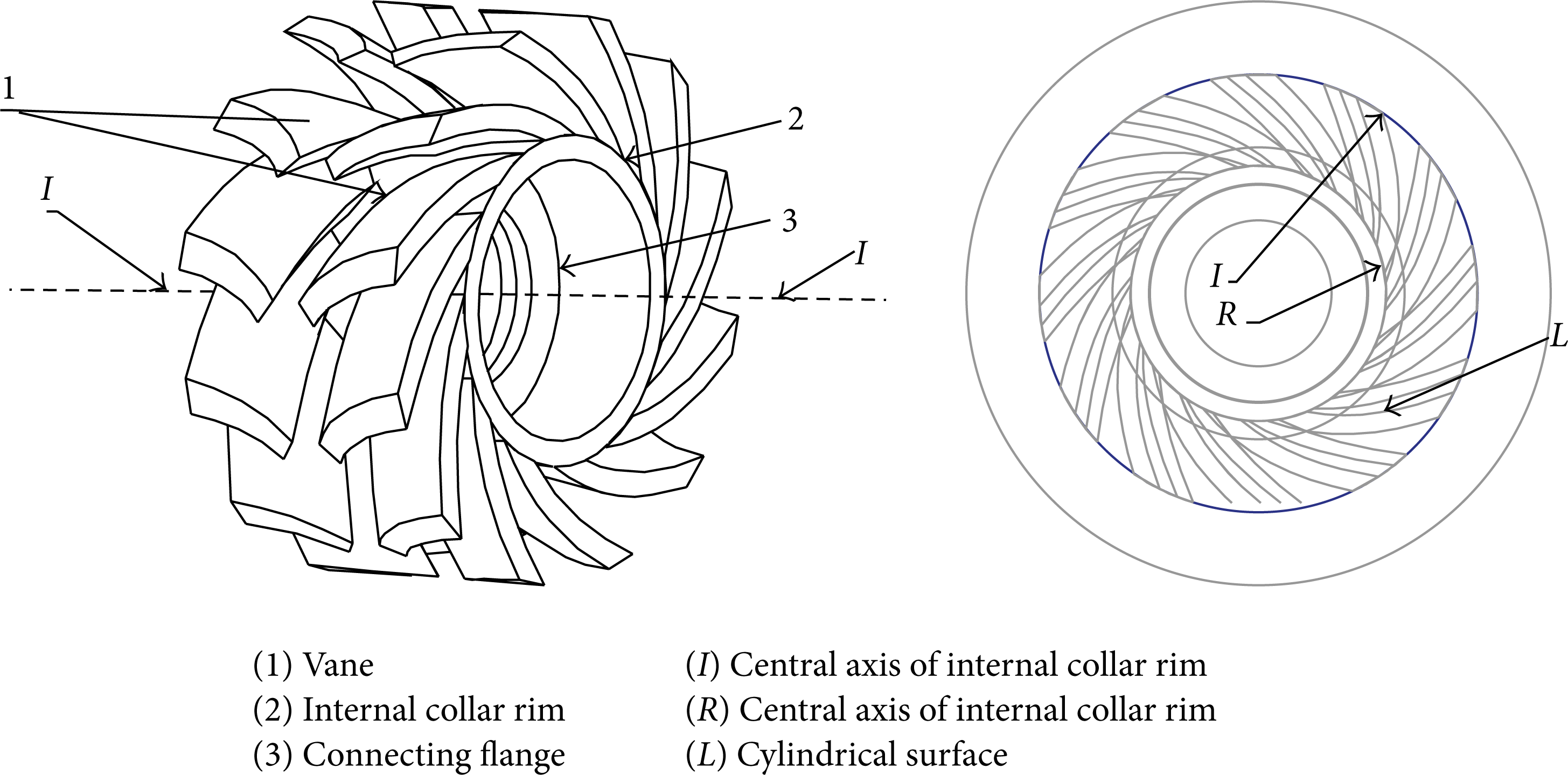
Structure of semistep walking wheel modeled on impeller.
2.2. Working Principle of the Semistep Walking Wheel Modeled on Impeller
The rover may encounter the terrain that is full of soft soil and obstacles as well as steep hill, which make the wheel sink into the soil more probably [15]. In this case, bulldozing resistance increases rapidly and becomes the main resistance of the rover because the front and sides of the wheel would be full of lunar soil. First of all, the width of wheels has significant effects on compaction resistance, while blades lay into two rows on the internal collar rim of this new type of wheel, which would decrease the effective width of the wheel. By this way, bulldozing resistance decreases as well, for the sections are disconnected. After that, two rows of vanes are shaped like the reverse eight in reverse. It is similar to the design of decorative pattern on the existing car tires, which enable us to decrease the steering resistance and increase the wheels’ adhesion force. In the meantime, eight-shaped vanes, just like a suit of thorns mounted on the wheel, provide more traction force for the wheels than other types of wheel whose vanes are perpenticular to the internal collar rims [16]. What is more, lunar dirt may float into this kind of open-type wheel and magnify the resistance of walking, even ruining the structure of the rover's wheels. Nevertheless, vanes lay in shape like inclined arc on the wheels introduced in this paper that enable the dirt expel from the wheel instead of chocking up the internal wheel.
2.3. Traction Analysis of Semistep Walking Wheel Modeled on Impeller
2.3.1. Analyze of the Force Applied on the Front of the Vane Based on the Coulomb's Earth Pressure Theory
When walking on the soft dirt, the vanes of the semistep walking wheel may sink into the lunar soil. The interaction between the front side of the vanes and the soil resembles the passive earth pressure presented in the Coulomb's retaining wall theory [17], which could be used to analyze the force effect on the front side of the vane. To simplify calculations, here we assume the single pair of the vanes as a curve surface and the pavement that the wheel was walking on is horizontal, as shown in Figure 2(a). Depth of the vane caved H, front side of the contact surface between vane, and soil AB, the angle between vane and the vertical direction, is α. The wheel extrusion the soil while walking on the soil, and then a sliding crack body ABC formed in the inclined top of the wheel vane. The angle between the sliding plane of the body AC and the horizontal plane is θ. Based on the theory of limit equilibrium, soil above the sliding plane, the sliding crack area, retains a condition of passive limit equilibrium. However, the soil beneath the sliding plane maintains an elastic state.
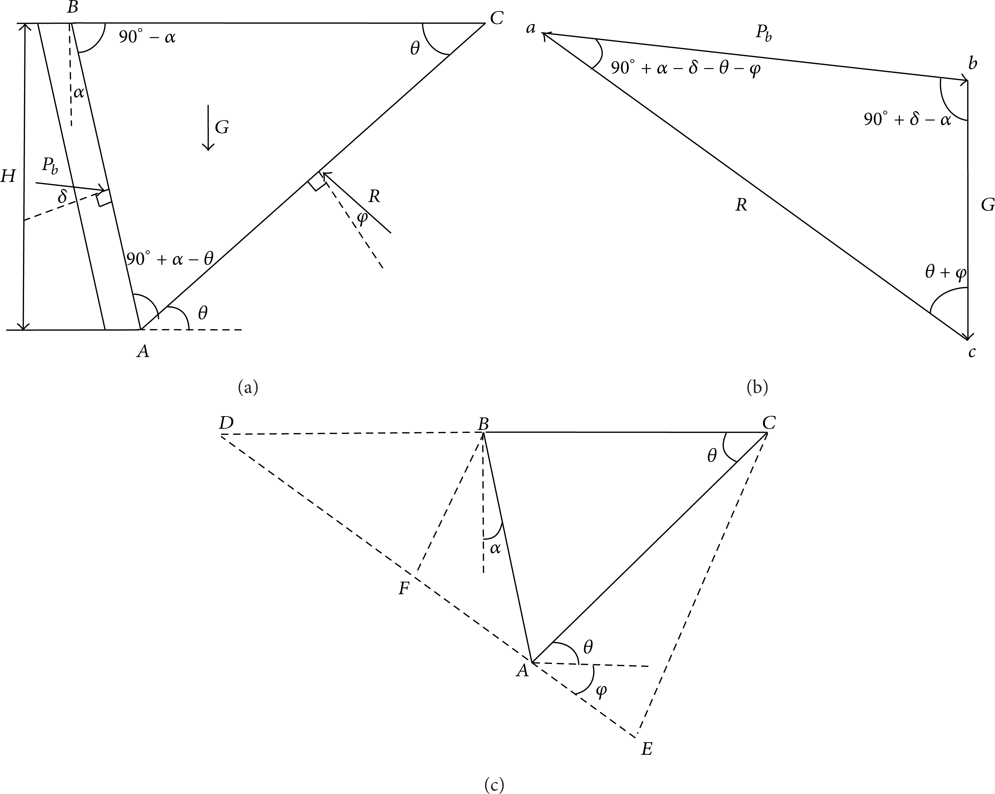
Derivation graph of passive earth pressure.

Force diagram of the bottom surface and side of the vane.
The forces applied on the sliding crack body consist of the following several parts: gravity G of the sliding crack body ABC, which is vertically downward, applied on the gravity center of ABC. Reactive force R acts on the sliding plane that formed an angle ϕ, internal friction angle of lunar soil, with its’ normal. Reactive force P b acts between the front side of the vane and the sliding crack body ABC, which equals the passive earth pressure between lunar soil and the front side of the vane; however, they two lay in the opposite directions. Meanwhile, the force P b , acts above the normal, and the normal of the front side of the vane formed an angle δ, the internal friction angle between lunar soil, and the front side of the vane.
The force action lines form a closed triangle, for the sliding crack body staying in balance, as shown in Figure 2(b). A series of assistant lines are needed to deduce the value of P b as shown in Figure 2(c). A straight line is made to form an angle with horizontal plane, and the angle lays beneath the horizontal plane, which means ∠CAE = θ + φ. After that, extent line AE is in the opposite direction. It would intersect with the extended line of CB on D. To acquire the line CE we conducted via the point C and intersect with the line AE on E. Then we made the equation ∠AEC = 90° – α + δ in the triangle. Consequently, Δabc ≅ ΔCEA is obtained from the analysis ahead. Then,
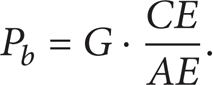
The weight of the sliding crack body means area of triangle ABC times the volume of the lunar soil γ0. Consider

Here plug (2) into (1), which makes

Triangle ΔCDE is similar to ΔBDF, which makes AB,BD,BF,AD,DF constants. While the length of AE is changed with the variation of length of segment AC, which means the length of sliding plane, which is changed with the variation of slant angle of the sliding plane. As a result, passive earth pressure would be changed with the alteration of AE. Based on the extreme conditions,

The condition of maximum value of the passive earth pressure is as follows:

Unknown values are calculated based on the sine theory, and then substitute equation (3) into (5) in. We can obtain
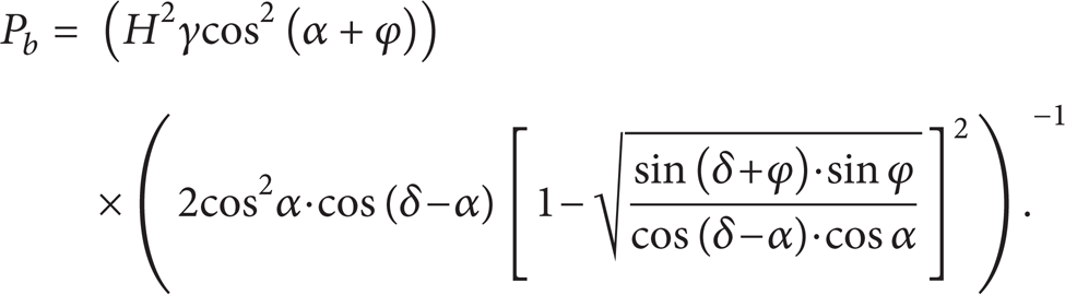
When the wheel scrolls ahead, the rear section of the wheel sunk in the earth generates the pressure to soil. To simplify calculation, the pressure is assumed to be uniformed q0. Here uniform load can be converted into the height of lunar earth, shown as h0 = q0/γ0. A value h0 would be added to the caved depth of the original vanes. Then plug the h0 = q0/γ0 in (6) to obtain
Equation (7) means the passive pressure on unit length when the load condition of the surface of the lunar earth is homogeneous, while the whole passive earth pressure applied on the width b0 of the vanes expressed as

2.3.2. Other Thrust Applied on the Vanes
In the process of the vane into the soil and out of the soil, the two sides and bottom of the vane are also acted by the shearing stress of the lunar soil, which is τ1 and τ2, in addition to the earth pressure acting on the surface. The bottom surface of the vane is acted by the frictional force (Fm) of the lunar soil [18]. The reaction forces of the above three force are also thrust acting on the vane, as shown in Figure 3.
The total shearing force (Fτ) equals the shearing stress multiplied by the shearing area

In the above equation, c is lunar soil cohesion; ψ is a parameter relevant to the depth (H) of the wheel. H>b/2,
The default frictional force always acts in the horizontal direction and it is equal to the vertical load of the vane multiplied by friction coefficient of the wheel and lunar soil. Consider

In the above equation, μ m is friction coefficient of lunar soil and the bottom of the vane.
In summary, the maximum thrust, which the wheel can obtain on nonslipping condition, includes the horizontal component of the passive earth pressure, the shearing stress of the lunar soil, at which the two sides and bottom of the vane are acted, and the frictional force (F m ) of the lunar soil, at which the bottom surface of the vane is acted. The total thrust is expressed as

2.3.3. Traction Force Calculation of Semistep Walking Wheel Modeled on Impeller
Setting the wheel can straight driving on flat lunar soil, so there are not slope resistance and steering resistance. Adherent resistance is greatly reduced, due to the special design of the vane of this wheel, so that it can be ignored. There is not track grouser resistance, due to the fact that the walking wheel is not track grouser. The resistance (F z ) includes compaction resistance (R c ) and bulldozing resistance (F t ) [19]

In the formula, F t is bulldozing resistance and ϕ0 is soil internal friction angle; c0 is soil cohesion; N c , Nγ are coefficient of friction Angle to the soil. Other unknown quantity could be worked out for using following formula;
In summary, the traction force formula of semistep walking wheel modeled on impeller is

3. The Application Simulation of Semistep Modeled on Impeller Based on ADAMS
In order to complete the simulation of the walking wheel on the lunar rover, there introduce the automatic dynamic analysis of mechanical systems (ADAMS) model of CE-3-X suspension, which is provided by the China Aerospace Science and Technology Corporation Eighth Institutes [17]. And putting the UG (Unigraphics NX) solid model of semistep walking wheel modeled on impeller into ADAMS, it can constitute a complete model of the simulation vehicle. Overall quality of the vehicle is 120 kg and uniformly distributed above the six wheels. The diameter of semistep walking wheel modeled on impeller is 300 mm. The width of the wheel is 140 mm. The effective width of vane is 122.5 mm. The acceleration of gravity is 1/6 g. The lunar soil parameters are derived from the lunar soil parameters in performance test of LRV of medium traffic ability, as shown the deepened part in Table 1.
Lunar soil parameters in performance test of LRV.

In order to analyse the performance of this walking wheel, the following article simulates the movement of the lunar rover, under these three conditions: straight driving, one-side surmounting obstacle, and two-side surmounting obstacle.
3.1. Straight Driving
The lunar rover drives straight-line by the speed of 200 m/h on the formation lunar surface, as shown in Figure 4. Velocity curve of the lunar rover is shown in Figure 5. The speed of lunar rover can be stabilized at around 200 m/h after being preaccelerated. Wheels can ensure the lunar rover walking on the straight.

Straight driving model of lunar rover.

Velocity curve of the lunar rover walking on the straight.
3.2. One-Side Surmounting Obstacle
One-side surmounting obstacle is setting raised obstacles on the one side of the wheel. The height of obstacles is 150 mm. The length is 200 mm. The width is 1500 mm. The inclination is 40°. The results of simulation show that the lunar rover can over the obstacles by the speed of 200 m/h, as shown in Figure 6. Figure 7 gives the simulation process of the lunar rover one-side surmounting obstacle.
Velocity curve of lunar rover one-side surmounting obstacle.

Process of the lunar rover one-side surmounting obstacle.
Two-side surmounting obstacle is that the two sides of the wheel must run over the obstacles. The height of obstacles is 100 mm. The length is 200 mm. The width is 1500 mm. The inclination is 25°. The results of simulation show that the lunar rover can run over the obstacles by the speed of 200 m/h, as shown in Figure 8. Figure 9 gives the simulation process of the lunar rover two-side surmounting obstacle. Compared to the ability of one-side surmounting obstacle, the ability of two-side surmounting obstacle is reduced, because the wheels getting off the ground cannot provide the traction as same as on the straight so that the total traction is declined.

Velocity curve of lunar rover two-side surmounting obstacle.

Velocity curve of lunar rover two-side surmounting obstacle.
The simulation in Figure 9 shows that semistep walking wheel modeled on impeller can ensure that the lunar rover walking on the straight has the speed stability and the stronger ability of surmounting obstacle.
4. The 3D Terrain Construction Method of Lunar Landing Area
4.1. Lunar Landing Characteristics and Analysis of Statistical Landscape Area
There is a certain statistical law between the diameter and quantitative distribution of lunar craters; namely, the relationship between the quantity and diameter of craters is approximately inverse proportion [20]. In the smooth mare region the distribution of craters is N(D) = 0.024D–2.06 [21]. In literature [22, 23], the formula of the number of craters per square meter whose diameter is greater than D within gentle mare regional was introduced. This paper presents how to construct the lunar terrain with the area of 900 m2. The number of craters within the scope of different diameter in the lunar terrain constructed in this paper is estimated according to the distribution formula of craters in the landing area model of Apollo 15, and the results are shown in Table 2.
The statistical results of the number of craters.

The shapes of craters are different between each other. The approximate contour is concave structure like bowl, and it is mainly composed of two parts. One is the relatively flat bottom, which is the main part and is the on the general meaning. Another is the peripheral crater cluster, which is formed due to the accumulation of massive sputtering materials after impact event occurred.
NASA described the typical contour of craters in literature [25], as shown in Figure 10. Figure 11 shows one of its profile approximate picture, where Zr is the height of crater cluster, Zd is the depth of craters, Dr is the width of crater cluster, and D is the diameter of craters.

The typical contour of craters.

Profile approximately picture.
The shape of craters also has association with the age of craters, as shown in Table 3. The shape of craters can be expressed by formula N = kDm, where N is one feature such as the height or width of crater cluster on [23], and D is the diameter of craters. Taking new crater, for example, the value of the depth of craters (Zd), the height of crater cluster (Zr), and the width of crater cluster (Dr) are shown in the following:

where rand (1) is a random number between 0 and 1. When solving the width of crater cluster, k = 0.25 and m = 1.011 are provided in literature [26]. Other three kinds of craters are randomly produced and are added to the fundamental terrain. Then the geometric structure related to the landing area is more realistic.
The type of craters and its statistical feature of shape [24].
Figure 11 is considered as reference in this paper. Two independent equations are used to approximately describe the inside like bowl and the edge of craters, and surface of revolution is used to approximately describe the whole craters. After being calculated, the equation of the inside like bowl and the edge of craters are shown in the following.
The inside like bowl: -D/2 ≤ x ≤ D/2

The edge: x ≤ -D/2 or x≥D/2

The three-dimension graph of craters that its diameter is one meter is simulated by using MATLAB, as shown in Figure 12.
The three-dimension graph of craters that its diameter is one meter.
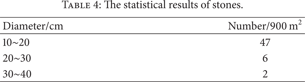
According to the formula “Apollo 15” landing zone model, we estimate the number of the stone with different diameter within the built lunar surface landing zone, about 900 square meters, as showed in Table 4. The shape of the lunar surface rocks covers a very broad range and standard shapes of the moon rocks are considered that the smallest scale and the largest scale ratio are between 1/1 and 1/5 [27]. In this paper, the mathematical model of rocks is established by using spherical, rectangular or the combination of spherical and rectangular. Due to weather and corrosion, stones surface may have dented. A set of random numbers should be added to the elevation values of the stones to make the surface more in line with its natural characteristics of stone. Matlab programming is used to obtain a 3D graph of 0.2 m diameter stones with different surface shape, as shown in Figure 13.
The statistical results of stones.

Three-dimensional graph of the stones with different surface shapes.
4.2. Construction of Fundamental Lunar Terrain Based on the Fractal Brown Motion
The most two important features of the fractal theory are self-similarity and fractal dimension. Using fractal method to study surface undulate and to simulate geomorphologic has become one of the most popular application fields of fractal geometry in recent years. Fractional Brownian motion generates the mathematical model of realistic scenery using the method of stochastic fractal. It can express many of the nonlinear phenomena in nature effectively, which is notable for the best random process of describing the real terrain.
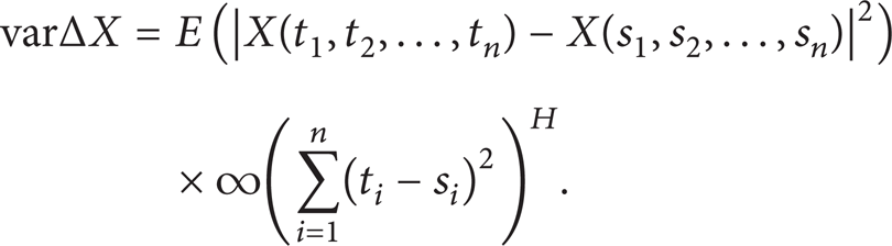
For any random increments
The randomized incremental ΔX variance depends only on the distance d as follows:

Specifically, the variance of Increment is in proportion with 2H exponent of distance d; that is,
In the equation above, fractal parameters 0<H<1. The random process is statistical and self-similariy, which can be used to describe two-dimensional or high-dimensional fractional Brownian motion. By inserting grid midpoint into the square grid and performing proper random offset for these midpoints, a vivid basic lunar surface is generated.
The two-dimention grid, as showed in Figure 14, the current grid resolution is δ, by inserting the midpoint into a grid and then refining them, and a new grid would be generated with the resolution of

Refinement of the grid.
The random increment corresponding to the 2D random variable mentioned in this paper is

And distance of the independent variable of the corresponding random function in its domain
If δ = 1, r is refinement factor in each iteration σ2 is the initial variance of the random function, and the value of the random function becomes 0 while δ is set for 0, By (19),

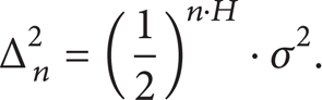
When the Nth iteration is applied, the grid resolution is r
n
and the corresponding random disturbance variance is

In the above process, the grid refining factor for
The rectangular grid mentioned above is set as the base plane. FBM surface with the property of fractal Brown motion characteristics could be generated by utilizing algorithm proposed above. FBM surface regularly is implemented to simulate many of the irregular natural objects, such as mountain profile, topography, and geomorphology. In this paper, 2D grid surfaces elevation data are calculated by Visual C++ program. The random perturbation range is adjustable, which mean that value should be preserved 0 and the variance of Gauss distribution should be kept 1. Based on the basis of the monthly table constructed terrain, lunar basic terrain constructed by this approach is shown in Figure 15.

Lunar basic terrain based on diamond square.
After elevation value of each point on the based terrain is calculated, we store them in the txt file, which can be converted into RDF file format. We import the rdf file into ADAMS and establish the landing zone basic topographic drawing by using a triangular mesh method, which could be utilized in the analysis of road spectrum properties, as showed in Figure 16.

Lunar basic terrain based on triangular mesh method of ADAMS.
This paper uses the random generation of the center point and the diameter and combined impacts crater, stones with the basic topographic. As for the impact craters, the random generation of the center point and the diameter refer to the method which identifies terrain characteristic and the type of impact craters according to the lunar surface area location information. If the type of the impact crater located in the same area is unchanged, then enter the minimum crater diameter. On the basis of crater diameter and volume distribution statistics, we acquire the amount n that impact craters whose diameter is exceeding the prior value. Afterward ni is selected randomly in the range of 0 tons and calculate the minimum diameter of the impact craters Di, which is supposed to be the diameter of the crater diameter. By using the stochastic method, we acquire the horizontal and vertical position of impact craters and calculate the impact area of the crater using its diameter and then elevation values in impact area could be calculated and the total elevation value should be modified. After the ns th cycle, total regional effect caused by the impact crater is calculated. Impact craters and stones would be combined with the fundamental terrain according to the random method, as showed in Figures 17 and 18.
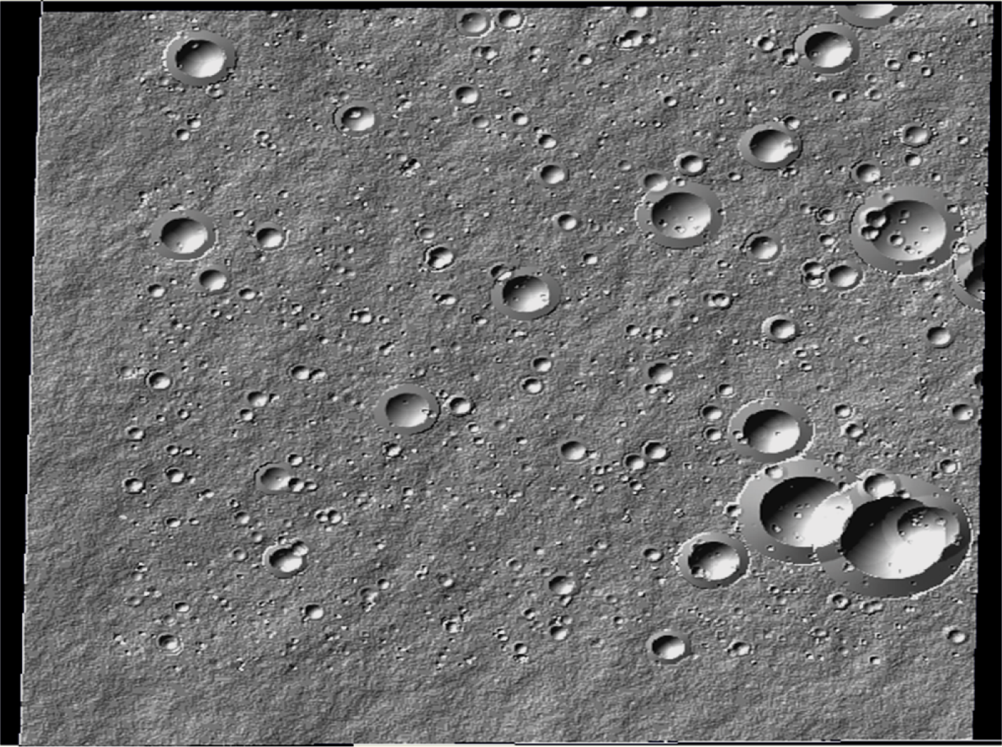
The lunar surface terrain with craters.

The lunar surface terrain with craters and stones.
Reconstruction topography of the lunar surface based on the 3D elevation value and kinematics and dynamics simulation in the lunar terrain virtual environment is the focus of this study. We use Imageware to convert the data file, virtual lunar surface 3D data elevation values, to ASC II Delimited (Label) format, which can be displayed by scatter. After space sampling, we simplify the data point at a specified interval and obtain information about the landing area point clouds section line of point clouds by using the method called the “cut blade” along with the direction of the y-axis and z-axis, respectively. And then create the lunar surface is created in Imageware by using the surface of UV direction, as showed in Figure 19(a).

The lunar surface terrain with craters and stones.
Surface reconstructed in the Imageware is 2D graphics so the surface file could not be imported into ADAMS to generate 3D entity model directly. However, on account of the unified standard data interface between UG and Imageware, we could create a model in UG using parasolid format, a kind of 3D solid model, which could be imported into the ADAMS directly. Therefore, we use UG to extend the 2D graphic builds in Imageware to 3D solid model, as showed in Figure 19(b). And then the 3D solid model and lunar rover CATIA model should be imported into ADAMS to conduct motion performance simulation analysis for lunar rover, meanwhile ADAMS computes the trend of the pitching angle, roll angle and yaw angle, and the force situation of the vehicle body and each wheel, respectively, when simulating a lunar rover landing on the virtual lunar surface environments, as shown in Figure 19.
In order to analyse the motion and mechanics performance of lunar rover mounted the semi-step wheel more effectively, the dynamics simulation software needs to be applied. ADAMS aims to multi-body dynamics analysis and it's the most commonly used and effective [28, 29]. In case, soil mechanics equations are imported to ADAMS. The stress condition of wheels on soft soil could be indicated. To set the control objectives and control strategy in the control module in ADAMS, the simulation system of soft terrain environment can be established [30]. The following part shows the simulation examples of application of the walking wheel.
5. Road Spectrum Simulation Analysis of Lunar Rover
It is difficult to simulate the actual working conditions of the lunar surface road, or to obtain both the roughness of lunar road and the mechanical vibration characteristics of rover on lunar road with specific roughness. In view of the fact that the NASA had sent their lunar rover to moon successfully, we referred to the relevant literature on their research about lunar surface roughness and road spectrum. By using 3D solid lunar pavement models with three different road roughness constructed by of UG, Imageware and ADAMS, we gained the mechanical vibration characteristics of rover on lunar surface with different roughness.
5.1. Power Spectrum of Three Typical Lunar Surfaces
Figure 20 shows the power spectral curve of three different types of lunar surface proposed in [31, 32]. We use multipoint curve fitting method to establish mathematical model of power spectrum on three typical lunar surface environments based on Figure 20.
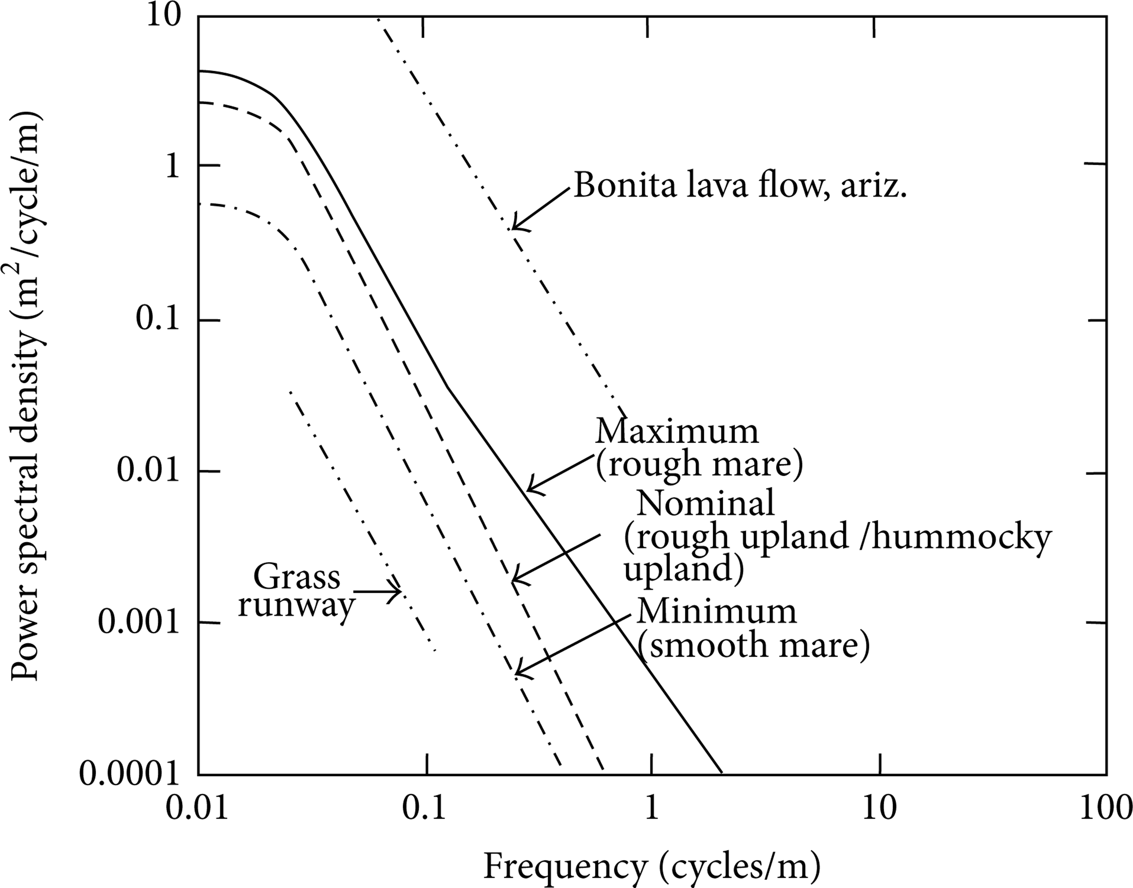
Surface power spectral curve proposed in US references.
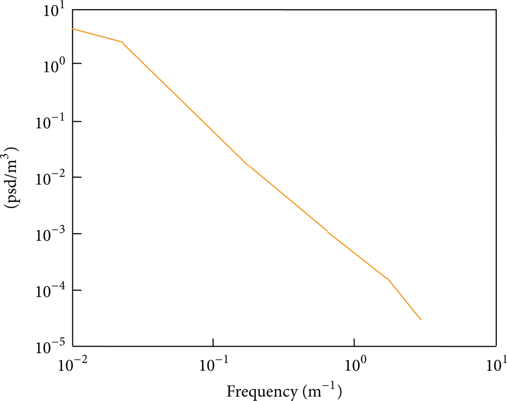
Lunar surface power spectrum on smooth mare expression is as follows:

where PSD is lunar surface displacement power spectrum, the unit is m3, and n is space frequency and the unit is m−1. p1 = −4.617, p2 = −27.3, p3 = −53.81, p4 = −35.58, q1 = −2.934, q2 = −5.185.
Figure 21 shows the surface power spectral curve of smooth mare drawn by the mathematical model based on (24).

Surface power spectral curve on smooth mare.
Lunar surface power spectrum on rough mare expression is as follows:

where p1 = −6.412, p2 = −37.23, p3 = −72.11, p4 = −46.19, q1 = −2.99, q2 = −4.629.
Figure 22 shows the surface power spectral curve of rough mare drawn by the mathematical model based on (25).

Surface power spectral curve on rough mare.
Lunar surface power spectrum on roughness upland expression is as follows:

where p1 = −0.4521, p2 = −1.2, p3 = −0.6176, p4 = −2.029, p5 = −3.305.
Figure 23 shows the surface power spectral curve of rough upland drawn by the mathematical model based on (26).
Surface power spectral curve on rough upland.
To inspect the correctness of the mathematical model, we compare and analyse the road spectrum curve calculate by mathematical model, we just built the road spectrum curve proposed in literature, as shown in Figure 24.

Comparison between road spectrum curve calculate by mathematical model proposed in this paper and road spectrum curve from the other literature.
The graphic we illustrated above indicates that the road spectrum curve calculated by the mathematical model proposed in this paper is basically consistent with the road spectrum curve raised in other papers. Therefore, it is possible for us to calculate the roughness of the lunar surface by using the mathematical model we built.
5.2. Obtain Three Typical Lunar Surface Road Roughness
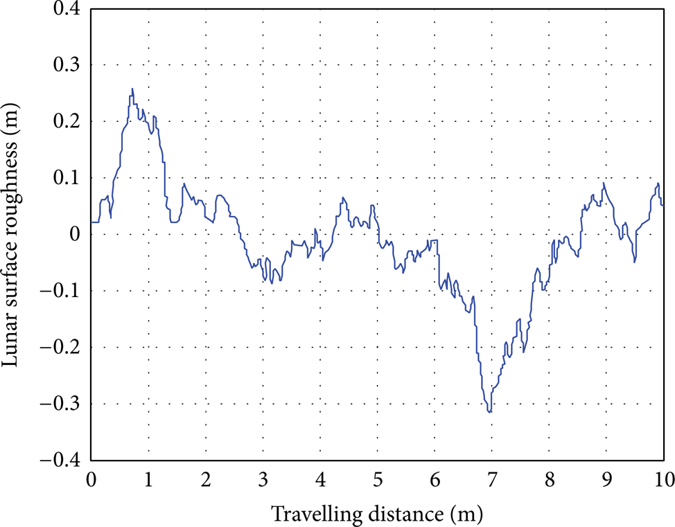
Performing inverse Fourier transform on the mathematical model of the road spectrum to obtain three typical surface roughness on lunar [33–36], Figures 25, 26, and 27 show road roughness curve of three typical lunar surfaces we actually get.

Roughness curve of smooth mare.

Roughness curve rough mare.
Roughness curve rough upland.
5.3. 3D Road Model Construction and ADAMS Simulation Analysis
Using Imageware and UG to construct 3D solid model with three different types of roughness based on data of three types of lunar surface environment, the width of solid model is 5 m, 1the length is 10 m and the resolution of 50 mm.
The length is 10 m and the resolution is 50 mm. By importing 3D lunar surface solid model and the rover model into ADAMS, the situation when the rover model is travelling at 200 km/h and 100 km/h will be simulated. The acceleration of the centroid at vertical direction is output and shown in the Figures 28, 29 and 30.

Centroid acceleration simulation video and output curve when the rover travels at smooth mare.

Centroid acceleration simulation video and output curve when the rover travels at rough mare.

Centroid acceleration simulation video and output curve when the rover travels at rough upland.
The acceleration curves we listed above show that for the rover traveling on the smooth mare, rough mare and rough upland with different roughness at the same speed, the maximum acceleration of centroid increases at the same order. The maximum acceleration of the centroid increases with raising the rover traveling speed on a certain roughness road. When the lunar rover is travelling at 200 m/h on the smooth mare, rough mare and rough upland, the maximum acceleration of centroid is approximatedly 0.5 g, 1.5 g and 1.8 g respectively.
The centroid acceleration time domain signal of the rover should be processed by Fourier transform (FFT) and window function, and then it is possible to obtain a centroid acceleration amplitude spectrum. Figures 31, 32, and 33 illustrate centroid acceleration amplitude-frequency curve of the rover traveling on three types of road environment of the lunar surface with different roughness, respectively.
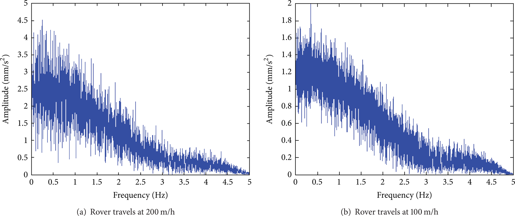
The amplitude-frequency curve of the rover centroid acceleration when rover travels at smooth mare.

The amplitude-frequency curve of the rover centroid acceleration when rover travels at rough mare.

Amplitude-frequency curve of the rover centroid acceleration when rover travels at rough upland.
Amplitude-frequency curve indicates that, when the rover is traveling on three different road surface roughness of the lunar surface environment at two different speeds, the centroid acceleration main frequency of the rover maintains approximately 0.5 HZ.
6. Conclusion
We designed a new type of semistep walking wheel modeled on impeller based on vehicle-terramechanics. The double row and in reverse of vanes and the vane's outside cross-section of circular cylindrical surface can give full play to the respective advantages of the traditional wheel and walking wheel on different road conditions. Based on the Coulomb theory of passive earth pressure, we obtain the traction formula of the walking wheel and derive the thrust formula of semistep walking wheel modeled on impeller's vane. There are still some shortcomings in this paper, such as analysis of only one group vane's force and the theory of soil mechanics is still in primary stage, so the next step is to depth theoretical exploration. Also, the simulation model is created. The smoothness and ability of surmounting obstacle of the walking wheel have been verified. Obviously the samples of several conditions are insufficient to fully verify the integrated nature of the wheel, so more conditions need to be simulated and analyzed.
This paper presents how to construct lunar landing terrain. By means of analyzing the typical statistic characteristic of Lunar terrain, the crater and boulder models are firstly put forward, then the second step is to construct basal lunar surface by using Btown Fractal Motion, the next step is to add craters and boulders based on the Known Diameter Algorithm and Random-create Diameter Algorithm. Using reverse engineering software to construct the lunar landing terrain and fulfill lunar rover kinematics and dynamics simulation, American literature provides power spectrum curve of lunar terrain environment; for reference, the spectral characteristic of three different lunar terrain roughness is educed by using reverse engineering algorithm. Simulation results demonstrated the frequency of vibration mechanics properties of different roughness surface. The simulation results show that the centroid acceleration frequency rate of lunar rover does not exceed 0.5 HZ.
Conflict of Interests
The authors declare that there is no conflict of interests regarding the publication of this paper.
Footnotes
Acknowledgments
This work is partially supported by the National Natural Science Foundation of China (Grant nos. 51205038 and 51208500), Xinjiang Uygur Autonomous Region Young Doctor Talents Training Project (Grant no. 2013731016), Chinese Postdoctoral Science Foundation (Grant nos. 2012M521824 and 2013T60904), and the Fundamental Research Funds for the Central Universities (Grant nos. DUT13JS14 and DUT13JS02). The first author would like to thanks Dr. Zhang Ronghui, for the valuable discussions in improving the quality and presentation of the paper.