
Abstract
In spite of many benefits, since a target RF should be able to react to real time user commands even during system power-off, RF remote controls generally require more standby energy than IR manner. Therefore, in this paper a multifunctional RF remote control (MRRC), which is capable of providing larger coverage and various services, is introduced, and an ultralow standby power operation method for target RFs, utilizing an extended preamble transmission and a variable length periodic preamble sensing according to system power states, is proposed. In addition, a prototype and implementation details are also described. In order to evaluate the proposed MRRC, several experiments are conducted, and each performance of MRRC is also compared with ZigBee RF4CE no power saving and power saving mode. The experimental results demonstrate that the MRRC system enables not only ultralow standby power operation during system power-off but also low power operation even in system power-on state. In spite of ultralow standby power operation, the experimental result also shows that the MRRC provides reasonable response time to user command.
1. Introduction
After the first wireless remote control, Flash-Matic developed by Eugene Polley in 1955 has been introduced and the IR (infrared) remote control has been used dominantly for TV and other home appliances for about more than 30 years. The IR remote control provides simple and low power connectivity to remotely control several home appliances but also has the following limitations: one way communication, line-of-sight constraint, and one-to-one communication only. In addition, to receive commands from a remote, power of an IR receiver remains active. Recently, as the number of smart appliances is increased, the demand for a new remote control to overcome the limitations of IR remote controls is arising. Furthermore, the rapid advances in wireless systems and user interfaces have accelerated the advent of a new remote control using several wireless systems or various user interfaces [1–8].
Remotes [1, 2] using Bluetooth support simple, familiar association with smart phones. However, due to interference problems with other wireless systems such as Wi-Fi and scalability problems that a slave is allowed to be paired with only one master (target) device, the spread of a remote control based on Bluetooth in various home appliances is limited. In addition, ZigBee RF4CE [5] (Radio Frequency for Consumer Electronics) has been emerged as a representative RF remote control, which enables one-to-many communications based on two-way communications and provides larger coverage due to no line-of-sight constraint.
In spite of many benefits, the RF remote controls, such as RF4CE, generally require more standby energy than IR manner, and thus it might result in increase of standby power consumption in home. In particular, recently as concerns about standby power reduction is being increased much more, some research focuses on reducing standby power in home appliances [9, 10, 16, 17].
Therefore, this paper deals with a problem of how to reduce standby power consumption in home, and, in particular, reduction of standby power consumed in RF remote receivers, which should be able to react to real time user commands even if the system power is off, is focused on. Recently, as home appliances controlled by remote controls are increased, the problem reducing standby power in home appliances is considered to be challenging.
The remainder of this paper is organized as follows. In Section 2 several researches related to our work are investigated. Section 3 introduces RF low power listening and the proposed idea is described in Section 4. Section 5 shows an example of the MRRC operation. Experimental results and performance evaluations are presented in Section 6. Section 7 provides some concluding remarks.
2. Related Work
Over the last decade, there have been a number of researches [1–8] on new remote controls for various home appliances to replace conventional IR remote controls. Kim et al. [3] proposed a new remote control interface using a touch screen and haptic interface. Park and Lee [4] proposed a remote for smart TV using a user pattern recognition technology through a camera placed on TV. Even though these new interfaces for a remote control can provide more convenient environment to users, these might require more complex remote control method and be difficult to apply to various other target systems other than TV.
On the other hand, RF remote controls [5–8, 11] can take advantage of similar user interface to conventional IR remotes and thus enhance its performance and functionality without learning a new remote interface. Han et al. [5] proposed a home appliance control scheme using both IR remote and ZigBee RF communication. Each power outlet and dimming lights are equipped with ZigBee RF module, and they are managed by a ZigBee controller, which is controlled by an IR remote control. Hwang et al. [6] proposed an enhanced version of ZigBee to IR remote [5]. ZigBee to IR remote control performs a remote function for appliances requiring IR remote control, and ZPA (ZigBee Power Adaptor) manages systems requiring power control. Kim et al. [7] proposed a universal remote control having various communication interfaces using a mobile device to overcome limitations of a conventional remote control such as interface complexity and specific application constraint. A mobile device is equipped with Wi-Fi and additional RF module, and RF to relay is used to control power control devices, RF to IR is also used to control conventional appliances, and Wi-Fi is used for Internet access or CCTV.
Finally, the demand for a new remote using low power RF urged to the advent of a new standard ZigBee RF4CE [8] by ZigBee alliance in 2009. The RF4CE provides one-to-many communication and larger coverage over IR remote control, which is limited in line-of-sight. In addition, Hwang [11] proposed an interference which avoided RF4CE in 2.4 GHz ISM band.
In parallel with research on a new remote control, there have been some researches [5, 12–14] on reducing standby power in home. Tsai et al. [12] proposed a standby power reduction method for lighting devices by adaptively controlling lights according to human movement. Han et al. [5] and Han et al. [14] proposed a home energy management scheme in which a power outlet has a function to cutoff standby power if power consumption goes below a predefined threshold and a home server allows users to control home appliances outside the home.
In spite of a lot of efforts to reduce standby power in home, there have been only a few research on standby power minimization of a remote receiver. Kang et al. [13] proposed a remote control and remote receiver based on autonomous power in which transmitter accumulates energy in receiver using laser diode, and an IR receiver is powered by the stored energy. However, this method requires considerable energy in transmitter.
RF standby power minimization has been actively studied in wireless sensor network area. In particular, LPL (low power listening) methods [9, 10, 16, 17] are used to reduce unnecessary listening period and our work is also based on LPL. However, since most existing LPL methods are designed for wireless sensor networks in which sensors are massively deployed and have no intervention of human, it is impossible to apply the LPL itself for sensor networks to remote control applications.
Therefore, in this paper a novel low power RF communication based on LPL for RF remote control, which is capable of minimizing RF standby power by switching the RF listening period adaptively according to the state of target systems, is proposed.
3. Preliminary
Unlike the IR transmission using predetermined frequencies, RF communications are capable of transmitting various formats of data so that it is possible to provide more flexible and smart controls. In particular, the ZigBee RF4CE standard based on IEEE802.15.4 [15] enables low power remote control. However, the IEEE802.15.4 network depends on strict time synchronization between a coordinator and devices to maintain a superframe structure, and thus each node might waist unwanted energy due to idle listening. Furthermore, CSMA/CA based network can provide irregular latency so that users can feel some inconvenience.
Figure 1(a) shows a general RF frame structure. At the beginning of a frame, a preamble, which is a repeated pattern of “1” and “0” and is used as an indicator to notice the start of transmission, is transmitted. At the end of a synchronization word for sampling data, variable length data are transmitted and finally each frame is finished with the CRC (cyclic redundancy check), which is used to detect errors in the frame. As shown in the figure, to receive a frame the receiver should remain active before packet reception, and the active state should be kept until the whole frame is received. Therefore, for low power operation, an RF receiver, normally in sleep state, wakes up and receives a frame at the time when a transmitter sends a frame and then returns to sleep state again. In order to achieve this, the time synchronization between transmitter and receiver is required, and a duty cycle, which includes an active and sleep duration, should be maintained. However, it is difficult to correctly maintain time synchronization due to the effect of clock drift. Moreover, in remote control applications, user commands have unpredictable characteristics. That is, since most listening periods, which are in active state for the packet reception period, might become idle listening period; each target RF wastes considerable energy.
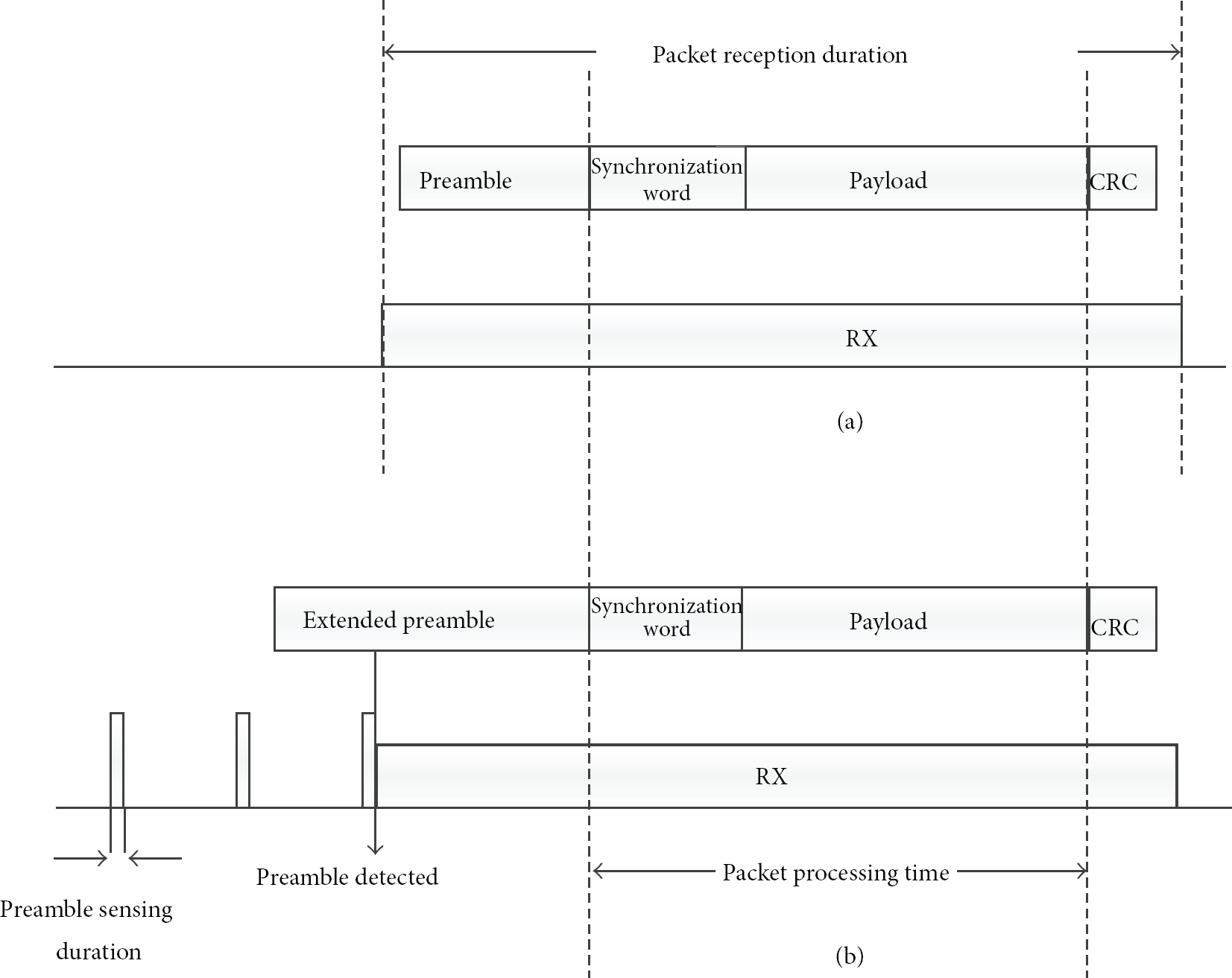
General RF packet structure versus extended preamble packet structure.
To address idle listening problems, there have been substantial researches [9, 10, 16, 17] on LPL to reduce idle listening periods. As shown in Figure 1(b), the LPL is different from general packet reception processing in that more expanded preamble is transmitted and a receiver is activated repeatedly only for a short duration (preamble sensing duration) to detect preamble transmission and the remainder of the period is in sleep mode.
Even though the LPL for sensor networks brings more energy conservation by reducing idle listening, the characteristics of sensor network application, in which sensors are massively deployed and have no intervention of human, are basically different from home remote controls, which are directly controlled by human. Therefore, in the following section, a new RF standby power reduction method based on adaptive low power listening is presented.
4. Multifunctional RF Remote Control for Ultralow Standby Power Home Appliances
In this Section, a multifunctional RF remote control (MRRC), which enables ultralow standby power operation of home appliances, is proposed.
4.1. Ultralow Power Listening with Variable Sensing Interval
In order to minimize power consumption of each target RF associated with MRRC, an extended preamble to trigger a target RF prior to each command is transmitted, and each target RF performs a periodic preamble sensing (PPS) to detect an extended preamble transmission for a very short duration. It is important to note that the length of preamble sensing duration, which is an active duration to perform preamble sensing, should be minimized to maintain a minimum duty cycle. Therefore, a minimum preamble sensing duration, an optimal length satisfying 100% successful preamble detection, is found through experiments in which total 100 trials are conducted. As shown in Figure 2, the obtained minimum preamble sensing duration is 4.8 milliseconds and the length is considerably shorter than minimum packet reception duration (188.8 milliseconds). The result reveals that inactive period of the MRRC system for an idle listening can be extended over 40 times compared to general packet reception schemes within the same period, and it might result in considerable energy saving.

Preamble sensing duration versus packet reception duration.
In addition, one of the major differences from other LPL methods is capable of providing minimizing standby power consumption of target RF by applying a variable length preamble sensing interval (PSI) according to the state of each target system, despite providing reasonable response time to user commands. Each target RF performs a PPS to sense an extended preamble for a short period and maintains sleep mode until the next PPS. Since an extended preamble transmission should be able to be sensed by a target RF during a PPS within a PSI, the length of an extended preamble transmitted by MRRC must be longer than a period of a PSI. The MRRC utilizes two different length PPSs: long PPS and short PPS. The long PPS is used to listen to a system power-on command by MRRC, and thus it is maintained for a relatively long period. That is, during system power-off, a target RF performs PPS with a longer interval. The longer the period is, the more energy can be saved, but response time of target RF with respect to user's command request is also longer. Therefore, through experiments a suitable interval value (3 seconds) is determined, which is the maximum waiting time that a user can tolerate. However, the PPS value is also configurable by a user. After system power-on, a target RF performs a short PPS with a shorter interval. Through another experiment, a suitable short PPS time (1 second) to wait for user command during system power-on is also determined.
If a user command is transmitted by MRRC, during PPS each target RF is triggered by an extended preamble and keeps a wait-for-command state until following command data are received. If the target ID in the received frame is not matched with my ID, the target RF returns to PPS mode again.
The MRRC also supports consecutive remote commands (i.e., volume up/down, TV channel set, etc.) during system power-on. In particular, to guarantee fast response time to consecutive commands, after the previous command is completed, both MRRC and target RF remain active for the same standby duration to wait for the next command. It is important to note that the commands generated during the standby period are transmitted as a general frame without an extended preamble. This standby duration is used to make a prompt response to consecutive commands by removing redundant delay to process an extended preamble. Furthermore, standby duration is reset whenever a new command is received within the standby duration, so that response time to consecutive commands is considerably reduced. If there is no following command for the standby duration, the standby timer expires so that the target RF returns to PPS state. Figure 3 shows a state transition diagram to perform a variable length PPS according to the states of a target system.
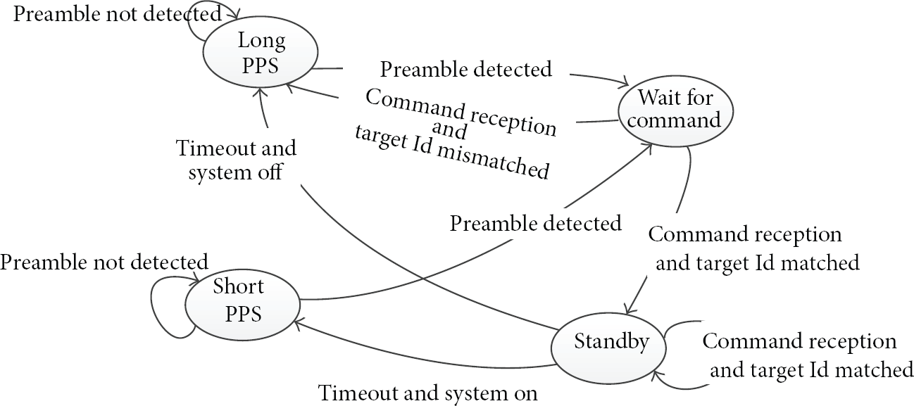
State transition diagram.
4.2. On-Demand Target Trigger
Another outstanding feature of the MRRC is asynchronous target trigger based on on-demand time synchronization. In order to cope well with on-demand user command, no global time synchronization but on-demand time synchronization is used in a MRRC. As mentioned in the previous subsection, to trigger a target RF which is performing PPS, an MRRC should transmit an extended preamble longer than a period of a PPS. As shown in Figure 4, all the target RFs performing preamble sensing at different time are triggered by an extended preamble of MRRC although preamble detection time of each target RF is different, and they receive simultaneously the command data transmitted at the end of the extended preamble. Therefore, all the target RFs and MRRC can be synchronized with each other. It is important to notice that each device that detects a preamble should be in active state for the wait-for-command duration. However, as shown in Figure 4, the length of wait-for-command duration of each target RF might be varied according to the point that a preamble is detected. That is, the earlier the preamble detection is, the longer the delay is until user command is received. Therefore, to minimize unnecessary delay, the MRRC also provides an interactive preamble termination method which can be applied when a target system is in user's line-of-sight. Figure 4 illustrates an example of interactive preamble termination. Whereas a normal extended preamble shown in the first command lasts for maxpreamblelength, the second preamble is terminated as soon as the button is released. That is, a target system can notice the MRRC user of is the preamble detection using a LED, and thus the system can provide a faster response time by terminating current preamble transmission as soon as the button of a MRRC is released. In particular, the method, which provides a flexible preamble transmission based on a feedback between user and a target system, can compensate relatively long response time in long PPS.

On-demand target trigger by MRRC.
4.3. Bidirectional Communication Capability
Unlike an IR remote control, the MRRC also has bidirectional communication capability. In particular, the MRRC is capable of controlling the length of an extended preamble through a feedback from a target system. Figure 5 illustrates an example of flexible PPS operation based on bidirectional communication between an MRRC and target RF. A target RF is performing PPS at long preamble sensing interval (LPSI) during system power-off, and the MRRC transmits a long preamble to trigger the target RF. At the end of a preamble transmission, user command is transmitted and target system carries out the received command. (As shown in Figure 5, the first command is system-power-on.) On carrying out the corresponding command, the target RF replies to the MRRC. To handle successive user commands, both target RF and MRRC remain active for the standby duration. As mentioned previously, if successive user command is transmitted during this period, the command can be transmitted without an extended preamble so that response time of the command is considerably reduced. Here, since the MRRC and target RF are synchronized by the command frame followed by an extended preamble, the two devices can maintain the same standby time. If there is no command for the standby duration, the target RF performs a PPS at short preamble sensing interval (SPSI) and MRRC returns to sleep mode. After standby duration expires, the MRRC uses a short extended preamble to trigger the target RF, which is performing a short PPS. The short PPS is used to consume RF power as low as possible even during system power-on and also provides the reduced response time over long PPS which is performed during system power-off. In particular, utilizing standby duration associated with short PPS enables fast response time by removing delay in the target RF and MRRC. If a target RF receives a system-off command from MRRC, the target RF turns off the system and responds to the MRRC. After that, to wait for additional consecutive command by user, the two devices keep active state for the standby duration, and then if there is no command during the time, the target RF performs long PPS again to save power.
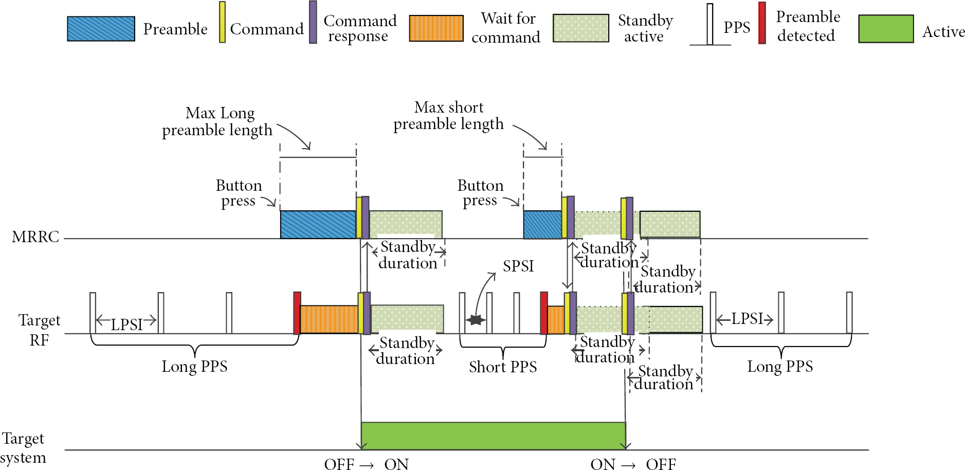
Bidirectional communication between MRRC and target systems.
5. Controlling Multiple Target Systems
Figure 6 shows an example of controlling a light, TV, and air conditioner using a single MRRC. First, in section A the light is already turned on, and other systems (TV and air conditioner) are powered off. TV and air conditioner are performing long PPS to reduce standby power, and the light is performing short PPS to react quickly to user commands. In section B, user turns on the air conditioner and immediately controls temperature of the air conditioner successively. As shown in the figure, the successive temperature control commands are processed immediately without extended preamble transmission. During the time, TV that is performing long PPS is triggered by the first command but returns to long PPS again after the command is received due to ID mismatch. Also, the TV is not even triggered by following short commands for the air conditioner. In section C, the user turns on TV through RF performing long PPS. At this moment, the extended preamble does not last for the maxlongpreambleduration but is terminated midway by user that perceives LED signal on TV, informing that a preamble is detected. That is, interactive preamble termination is used in that situation. In section D, the user switches channel. At that moment, since TV is powered on, RF is performing short PPS, and the MRRC sends the command after triggering RF by short extended preamble. This section has no more commands so that after standby duration the RF returns to short PPS. In section E, the user turns up the volume of the TV successively. Since volume controls are generated successively for the short duration, the rest of the commands are transmitted without extended preamble transmission, except for the first command with a short extended preamble. Therefore, the user can experience fast response to successive commands. In the final, user turns off TV and air conditioner. The RF, which is performing short PPS to provide relatively fast response, receives system power-off command and then goes to the long PPS mode after standby duration, to minimize standby power.
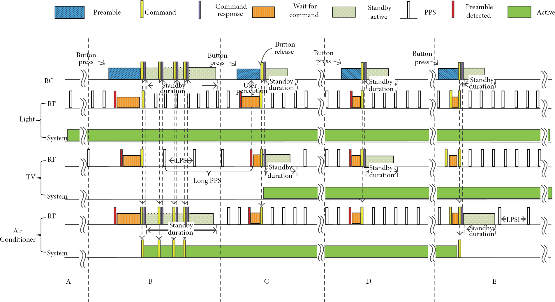
An example of MRRC operation.
6. Experimental Result
In this Section, a MRRC prototype and test bed are introduced, and experimental results are presented. In particular, each performance of the MRRC is compared with ZigBee RF4CE, which is the most representative RF remote control.
6.1. MRRC Prototype
Figure 7 shows an MRRC hardware prototype. The MRRC prototype is composed of 16-bit low power MCU and sub-1-GHz RF, which is capable of transmitting a variable length preamble. In addition, to generate user commands, simple push switches are used in place of key pads. The MRRC is also designed to cope well with several different events (external interrupts, timer interrupts, RF interrupts, etc.) through an event driven lightweight scheduler based on HAL (hardware abstract layer), which manages directly hardware. This development environment might also facilitate various MRRC application developments.

MRRC prototype.
6.2. Experimental Environment
For MRRC experiments, a target appliance emulator, which is a PC application software, is implemented. As shown in Figure 8, the used target emulators accept each command for light, TV and air conditioner, respectively, and individual RF is connected to the corresponding target system via USB. Each RF and a target can communicate with each other and the MRRC can control a designated target by target ID assigned uniquely. Emulator also plays a role in storing and analyzing data received from an MRRC.
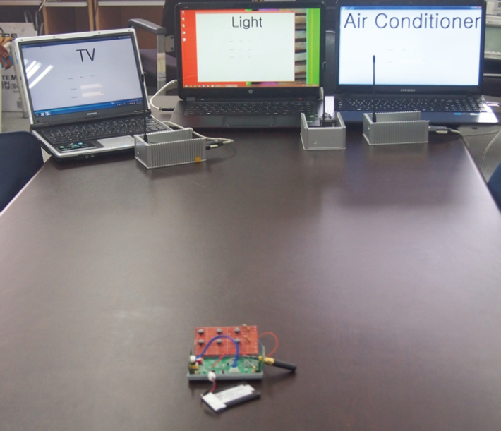
Test bed.
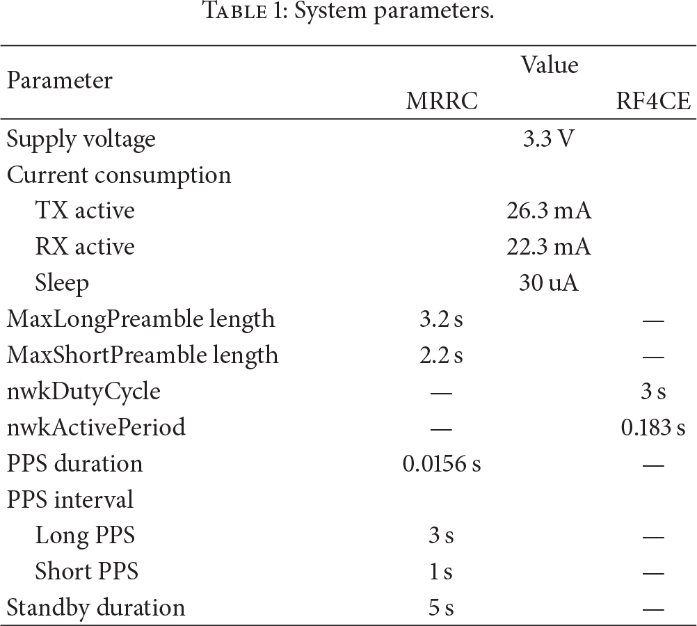
For comparative analysis of the proposed MRRC, ZigBee RF4CE is also implemented on the same hardware. RF4CE is designed based on IEEE802.15.4 PHY and MAC, and two different modes are implemented, respectively: RF4CE power saving (PS) and no power saving (NPS), which are specified in RF4CE standard. In NPS, all the target RFs wait for commands from an RF4CE remote control in a fully active mode, and in PS each target maintains repeatedly a duty cycle, which includes active state for nwkActivePeriod and sleep state for the remainder period. Table 1 summarizes main parameters used in our experiments.
System parameters.
6.3. Performance Evaluations
In this subsection, the MRRC performances compared with ZigBee RF4CE through various experiments are evaluated. First, how fast a target system can respond to a user command is evaluated by observing response time. Subsequently, how much energy efficient a target RF and MRRC is evaluated by analyzing energy consumption in various experimental environments. In addition, since PPS duration guaranteeing 100% reception ratio through experiments, as mentioned in Section 4.1, is applied, the experimental result regarding successful data transmission ratio is not presented in this paper.
6.4. Response Time Analysis
First, response time of MRRC, RF4CE PS, and RF4CE NPS is observed, respectively. The response time is a round trip time consumed from an instance when user presses a button of an MRRC until the MRRC receives a reply from the target RF. For the experiment, consecutive 10 commands with one second interval at every one minute for total 6 minutes are generated, and each reply time from target RF is measured. Each experiment is repeated 100 times and Figure 9 shows the result that calculates the average of measured value at each experiment. First, the RF4CE NPS presents fast response time less than 250 milliseconds with respect to each command, as shown in Figure 10(a). In the case of RF4CE NPS, since each target RF is always awaken for the packet reception, user command can be processed promptly without any redundant delay. On the other hand, RF4CE PS shows irregular response time distribution as shown in Figure 9(b). The result presents large deviation (300–3,000 milliseconds). In that mode, for power saving a target RF maintains a repeated duty cycle with a period of nwkdutycycle, presented in Table 1. Therefore, a target RF should wait to transmit the command until a beacon frame is received from the target RF (in general, the target RF plays a role in a coordinator), and finally the command is transmitted at the active duration of target RF, which is referred to as a superframe duration, in which a beacon frame indicates the beginning of superframe duration. That is, the irregular latency in RF4CE PS results from the fact that communications between a remote control and target RF depend on time synchronization based on a beacon transmitted periodically by target RF. Eventually, the irregular response time might bring users inconvenience. Finally, experimental result of MRRC is shown in Figure 9(c). The result shows that response time of the MRRC maintains normally 280 milliseconds, which is similar to the RF4CE NPS. It is noticeable that the initial system-on command shows long response time of 3,300 milliseconds. The MRRC performs long PPS with long interval to save standby energy during system power-off, so that initial power-on command requires longer response time than the following commands. However, since after system power-on each target RF performs short PPS, only the first commands out of consecutive commands at every command interval show response time of 1,400 msec. Furthermore, since the rest of the consecutive commands are transmitted without an extended preamble, they can maintain minimum response time as in RF4CE NPS.

Response time.

Energy consumption.
6.5. Energy Consumption
Energy consumption is one of the important performance factors for home appliances and remote control. To evaluate comparative performance, total energy consumed for the test duration under the same test condition is measured for MRRC, RF4CE NPS, and PS, respectively. Energy consumption of a target RF and remote control, respectively, is obtained from power consumed for 24 hours. More specifically, standby energy of target RF in fully standby mode in which a target system is power off but RF is ready to receive user command is observed, and also energy consumption in fully active mode in which various user commands are performed is observed. Since power consumption is different according to each target system (appliance), for our experiment power consumption of only RF in each target system is considered. All the experimental results present average energy consumption of each RF connected to each appliance emulator.
Figure 10(a) shows energy consumption of a target RF in fully standby mode (system power off) for 24 hours. It is shown that RF4CE NPS having fast response time of 250 milliseconds is considerably inefficient in energy aspect. On the other hand, RF4CE PS shows more efficient energy consumption than NPS. This is because the mode maintains a repeated duty cycle for the standby period. It is noticeable that a target RF in MRRC shows minimum energy consumption over RF4CE. The ultralow standby energy consumption of the MRRC results from maintaining minimum active duration only to detect preamble transmission and utilizing variable length PPS (e.g., long PPS during RF standby period). Furthermore, unlike RF4CE PS, MRRC does not require superframe management based on time synchronization by a periodic beacon frame between a remote control and target RF.
Figure 10(b) shows another experimental result. In contrast with the former experiment (full a RF standby), for this experiment, the target system is turned on and 10 commands are issued at every hour for total 24 hours. The result shows that the MRRC target RF is superior to two RF4CE modes. Two RF4CE modes also show almost similar energy consumption as in fully RF standby mode. This is because the two modes utilize the same power management in both standby mode and active mode. On the other hand, since the MRRC manages different length PPS according to the system power-on/off state, the MRRC can cope well with tradeoff between energy and response time. In particular, even though the target RF consumes more energy over fully standby mode by performing short PPS in system power-on state, the MRRC target RF shows more energy saving than the RF4CE PS.
Figure 10(c) presents experimental result of a remote control. For the experiment, user generates 10 commands using a remote control at every hour for 24 hours. In contrast with the former two experiments in which energy consumption of target RF is only focused, this experiment presents energy consumption of a remote control of MRRC, RF4CE NPS, and RF4CE PS, respectively. The result shows that energy saving of RF4CE NPS remote control is superior to MRRC and RF4CE PS. This is because RF4CE NPS remote control is normally in sleep mode, wakes up only when user command is generated, and returns to sleep mode again. On the other hand, since in the RF4CE PS remote control the generated user command should wait until beacon is received from the target RF, a remote control consumes more energy. In the case of MRRC, the on-demand user command can asynchronously trigger a target RF which is performing PPS. This feature results in minimizing unnecessary energy consumption in a remote control, and thus the MRRC shows similar energy consumption to RF4CE NPS.
7. Conclusion
In this paper a multifunctional RF remote control, which is capable of providing larger coverage and various services, is introduced, and an ultralow standby power operation method for target RFs, utilizing an extended preamble transmission and a variable length PPS according to system power state, is proposed. Furthermore, a target RF can promptly respond to on-demand user command by being asynchronously triggered by an MRRC. In addition, based on bidirectional communication between an MRRC and target RF, user can control multiple target systems with a single remote control.
A prototype and implementation details are also described. To evaluate the proposed MRRC, several experiments are conducted, and each performance of MRRC is also compared with ZigBee RF4CE NPS and PS. The experimental results demonstrated that the MRRC system enables not only ultralow standby power in system power-off state but also low power operation even in system active state. In spite of ultralow standby power operation, the experimental result also shows that the MRRC provides reasonable response time to user command. Finally, it is expected that these outstanding features of MRRC will be able to contribute to constructing ultralow power home network associated with smart appliances.
Footnotes
Conflict of Interests
The authors declare that there is no conflict of interests regarding the publication of this paper.
Acknowledgment
This work was supported by the Incheon National University Research grant in 2012.