
Abstract
Video surveillance system (VSS) is increasingly becoming important part in daily life. For traditional VSS, each camera stores streaming data to a centralized server. It will create a great volume of video data for a large VSS and may raise some issues in keeping daily video data to centralized server, such as limited bandwidth and storage insufficiency of server and lower reliability and scalability. In order to solve the problem, we have proposed an architecture for VSS based on well-developed peer-to-peer technique and emerging cloud computing. In this paper, we implement a large-scale VSS (LVSS) and propose an evaluation framework based on the proposed architecture. We implement the LVSS exploits inherent characteristics of P2P and cloud computing to provide an economic, scalable, reliable, and efficient approach to store streaming video. We conducted some experiments to evaluate effectiveness and efficiency of the system. The result shows that the proposed architecture outperforms traditional VSS in terms of effectiveness, efficiency, reliability, and scalability.
1. Introduction
Video surveillance system (VSS) [1] is useful facility to governments and law enforcement to maintain social control, recognize and monitor threats, and prevent/investigate criminal activity. It is applied to observation from a distance by means of electronic equipment (such as CCTV cameras) or interception of electronically transmitted information. In general, a VSS is composed of three components: front-end video capturing device, the central control platform, and user client [2]. The front-end video capturing device contains a camera and digital video recorder. The central control platform controls and handles the video dispatching and video frame compressing. Traditional VSS can simply be classified into two generations [3–5]. The first generation adopts analog device to capture continuous scene and transmit video signal to storage. The second [6] applies digital technologies to deal with capturing video streaming and storing them to a centralized server.
Due to the advances of consumer electronics and the increasing revolution of camera, VSS needs to face some issues in storing streaming video data, especially for large-scale VSS (LVSS). In a LVSS, such as a city-wide VSS for recognizing or monitoring threats or a large security service firm, it might tie up to hundreds or thousands of video recorders and need to store simultaneously all streaming video data into a centralized server or data center (DC).
The accordingly arisen issues of LVSS are insufficient bandwidth to centralized server and limited storage of the server. While the number of front-end devices (FE) is increasing, obviously, the required bandwidth to centralized server and storage size of the server will be considerably increasing with positive proportional to the number of FEs. Therefore, centralized server becomes the bottleneck of a LVSS. The scalability and extracting efficiency of video from the LVSS are also descending. Although a scalable and flexible data center network [7] can solve the problem, it as usual needs a lot of expensive network equipment and enough storage hosted in data center room.
In addition, reliability of LVSS is also an important issue. A dedicated server might fail to serve requests while the storage crashed. The LVSS is therefore losing its functionality. In other words, all FE devices are not able to store video streaming data into centralized server and all users cannot extract desired video. Therefore, the reliability of a centralized server will be descended to the LVSS. There are works [8–15] that have been proposed for supporting a framework of VSS based on various technologies. Unfortunately, most of them do not solve mentioned issues to support large-scale VSS.
Cloud computing [16, 17] has been witnessed and applied to various applications to provide elastic resource [18–21] in recent years. Many data-intensive applications in the cloud adopted Hadoop file system (HDFS) [22, 23], which is designed to store very large data sets reliably and to stream those data sets at high bandwidth to user applications.
To solve problems mentioned above, we have proposed an architecture for VSS based on peer-to-peer technology [24] and cloud computing, named P2PCloud [25]. The core concept of the proposed architecture is exploiting the concept of Hadoop file system to replicate streaming video to other FEs for improving the reliability of LVSS. The proposed architecture is composed of two major components; one is centralized server named directory node (DN) and the other is a lot of front-end video capturing devices (FE) with storage named peer node (PN). Each PN is not only storing streaming video into its storage, but also acting as replicas of other FEs. The DN is used to maintain the location of replicas of each PN and look for the location of replicas for each PN. A scheduling algorithm for selecting PNs to replicate video data is run in the DN. While a PN (named primary-PN, short for P-PN) wants to replicate its streaming video to other PNs (named secondary-PN, short for S-PN), it can inquire DN to get the location of replicas (S-PN).
Based on the proposed architecture, in this paper, we implement the components of DN, PN, and whole system to demonstrate the feasibility for LVSS and then propose an evaluation framework to evaluate the effectiveness, efficiency, usability, and scalability of the LVSS by conducting a variety of experiments. We exploited OpenCV (open source computer vision library) [26, 27] that is a real-time image processing library to process the caught streaming video. The result showed that the proposed architecture is superior in terms of scalability, reliability, efficiency, and bandwidth usage.
The paper is organized as follows. Section 2 introduces briefly the Hadoop file system and surveys other VSSs to find out the advantages and shortcomings. Section 3 describes our design philosophy of the architecture. We also present the selecting algorithm that can choose suitable peer nodes for replicating the streaming video. In Section 4, we define evaluation factor, frame transmission success rate, to prove system's effectiveness and efficiency. We also make a comparison with other systems. Finally, a concluding remark and future work are given in Section 5.
2. Background and Related Work
2.1. Hadoop
Apache's Hadoop is a framework that allows distributed processing for large data sets across clusters of computer using a simple programming model. Hadoop was built up by two important parts, map reduce and Hadoop file system (HDFS) [28]. In the Hadoop file system (HDFS) [22, 23], it provides global access to files in the cluster and is implemented by two kinds of nodes: the NameNode and the DataNode. An HDFS cluster consists of a single NameNode, a master server that manages the file system namespace and regulates access to files by clients.
In addition, there are a number of DataNodes, which manage storage attached to the nodes that they run on. NameNode is responsible for managing all metadata of file system, while DataNode stores actual data. HDFS uses commodity hardware to distribute the system loading with characteristics of fault tolerance scalability and expandability. In the HDFS, the NameNode executes the base system operation, just like renaming, opening, and closing, and determines the mapping table for each block in the DataNode. The DataNode directly accesses the file. It can serve reading and writing requests from the client.
In the HDFS, each file will be split into one or more small blocks, and these blocks are allowed to be stored in a set of DataNodes [29]. That means that it will store each file as a sequence of blocks, which are expectedly split as the same size but not the last one. The block size and replication factor are configurable per file. An application can specify the number of replicas of a file. The replication factor can be specified at file creation time and can be changed later. Files in the HDFS are write-once and have strictly one writer at any time. The purpose of a rack-aware replica placement policy is to improve data reliability, availability, and network bandwidth utilization [30]. For the fault tolerance, each block of a file is replicated and, by default, two backups of each block are stored by different DataNodes in the same rack and a third one is stored on a DataNode in a different rack. The NameNode decides the location of replication. One-third of replicas are on one node, two-thirds of replicas are on one rack, and the other third are evenly distributed across the remaining racks. The placement chosen for replica is to improve the reliability and performance.
A crashed DataNode is not available to be accessed in HDFS anymore. DataNode death may cause the replication factor of some blocks to fall below their specified value. It will make the replica mechanism break up. So, the NameNode constantly tracks which blocks need to be replicated and initiates replication whenever necessary.
2.2. Surveillance Systems
Due to the growth of security concerns, video surveillance applications have received significant attention from research and industrial communities. And traditional system model has a lot of problems in scalability, reliability, and efficiency. Therefore, many researchers proposed their system model to improve surveillance system quality. In this section, we are surveying similar surveillance environment and their research advantage.
In [10], authors proposed an overlay network architecture by application layer multicast with load balancing scheme to effectively provide ubiquitous video surveillance service. The proposed approach can provide Internet users with scalable and stable surveillance video streaming, since the simulations and results demonstrate that our improved optimization of load balancing via both averaging bandwidth and life time has better performance in overhead of control message, service disruption, and tree depth than the other optimization criterion.
In [11], authors presented a layered generic organizational suite for the development of sensor management framework (SMF) based on the service-oriented architecture. The sensor management system is studied from a layered perspective and the functional tasks carried by the SMF are categorized into three categories: sensor management, network management, and system management.
In [12], authors proposed a design of large-scale video surveillance system client based on P2P streaming. Given the particularity of video surveillance, such as high churn and the heterogeneity of user access network and delay tolerant network, authors also constructed the end-hosts into mesh application layer topology and adopted pull-push mode to deliver the data. Authors also designed the architecture of PPClient and gave details of its components. Through simulation and real system test, it shows its feasibility. PPClient conquered traditional server/client mode, which needs large number of infrastructures to support tens of thousands of users. By using P2P streaming technology, users act as consumers and at the same time they provide service to other users. Then the system's scalability is enhanced.
In [13], author conducted a cloud computing-based intelligent video monitoring platform which includes GVM, GPP editor, video surveillance software, and OpenCV middleware services. The proposed platform can let the developer monitor web cam remotely and receive the change of monitoring area via our video surveillance software.
In [14], authors presented a distributed and scalable video surveillance system, subcontracted by intelligent surveillance components (ISCs) and visualization surveillance components (VSCs) in compliance with functional labors. The VSCs constitute a multitier subsystem to visualize fused results of messages, key frames, streaming videos, and geographic context information. The system helps the operator to focus attention on interested events gathered from distrusted ISCs and presented by VSCs on map and three-dimensional homographic views.
In [15], authors proposed a video surveillance system based on cloud computing that collects multimedia streams generated by surveillance cameras, optimizes their transmissions according to network condition, and stores them in a cloud storage system in an efficient and secure way.
In [25], we have applied the data placement concept of Hadoop file system to provide fault-tolerant and efficient video access and applied P2P technology [24, 31] in order to improve the scalability, reliability, robust, and server cost. But, in the work, we only proposed an architecture for VSS without stating the implementation and evaluation for LVSS.
3. Architecture of a Large-Scale Video Surveillance System
A large-scale video surveillance system is similar to a generic one. Therefore, we referred to the previous work [25] to implement a large-scale video surveillance system. This section presents the architecture of proposed large-scale video surveillance system. The operation flow of video recording and video monitoring is also depicted. For details, reader can refer to [25].
3.1. System Architecture
Figure 1 shows the system architecture. In order to improve the scalability, reliability, and efficiency of proposed system, the DN is designed as a thin server, which is similar to the NameNode of HDFS. It is responsible for managing the metadata of PNs without storing any video data. In the design, the system can have multiple DNs for reliability issue. To simplify system architecture, we assume that the system has only one DN. The peer node (PN) is a front-end (FE) device and is responsible for storing video data, which can, according to their roles, be divided into primary-peer node (P-PN) and secondary-peer node (S-PN). Every deployed PN for a customer is firstly necessary to register their node information into DN before joining to the environment. The PN is termed P-PN. After registering the P-PN into DN, it then asks DN for giving two or more peer nodes (termed as S-PN) based on a replica selection algorithm to act as replicas. The functionalities of P-PN and the S-PN are the same except for their roles. P-PN and S-PNs compose as a replication group (RG). The DN also maintains all information of RGs. Therefore, each FE's video data in the architecture can be stored into three PNs; one is in P-PN that of course is the node FE tied up, and the other two nodes are in the S-PNs that are selected by the DN.

System architecture.
3.2. System Components and Their Functionality
This section is aiming at depicting the system components and their functionality.
3.2.1. Directory Node (DN)
The DN provides a centralized directory service and manager. All PNs are managed by the DN. Each PN periodically sends a heartbeat message with node's state information to DN. It contains the following components: authentication module (AM), replica manager (RM), replica selector (RS), and a database for keeping the information of the whole system. The AM is responsible for checking the authentication of any PN as well as assigning authentication key (auth-key) to both P-PN and associated S-PNs. The RM manages each PN and selects proper replicas for each PN through RS. Every PN can directly communicate with RM to get the location of replicas. The RS selects two proper S-PNs for a P-PN according to P2P technology. The functionality of each component is depicted as follows.
(i) Authentication Module (AM). This module has two major tasks. The first one is to store an authentication key (PK) of PN to DN. Each PN has 9 digital authentication keys and should be registered to DN. When a PN starts up, the AM must check whether the node is registered or not. If the node does not have PK, it will send DN a register request. The second one is to calculate peer node communication key (PCK) based on the PKs of peer nodes which want to communicate. The PCK is simply composed of two PKs of PNs that are in the same replication group (RG). And then the DN will send this PCK to the paired PNs, that is, S-PN, for future communication. By this key, the peer node can check whether the other node is in the same RG or not.
(ii) Replica Manager (RM). RM is a major module for listening and communicating with PNs. In the DN, RM manages each PN and selects appropriate replicas for each PN through RS. Every PN can directly communicate with RM to get the location of its replicas. Each PN can send a request to the RM, such as registering PK of PN and getting replicas. While RM receives a request for registering PK of PN, the RM will call the AM to register the PK into DN's database. If RM receives a request for getting replica of RG, the RM is first calling the RS module to get the replicas in order to form a RG and then sending a request to AM for getting replicas’ PCK.
(iii) Replica Selector (RS). RS is responsible for finding appropriate replicas for PN in order to form a RG. In order to improve access performance among the replicas of RG in a dynamic environment, we referred to resource-aware replica selection proposed by Chang et al. [32]. The RS will select appropriate PNs as the replicas according to every PN's states that contain number of replications in the node, node's bandwidth, and connection stability. If available PNs can be found and the number of nodes is enough, the DN will select appropriate nodes as the replica (S-PN) of requesting PN using well-known dynamic hashing function. And then the DN generates an authentication key and sends it to chosen S-PN for the request and for future request messages from P-PN (PN of initiating the request).
(iv) DN's Database. All the information of PN and RG is stored in the database, including the PK, PCK, and other metadata of the system. The information of PN comprises the unique ID, the peer node group, bandwidth, peer node's replica state, authentication key, and authorized state.
3.2.2. Peer Node (PN)
As mentioned above, according to the role of node, the PN can be classified into P-PN and S-PN; both have the same components. In the design, a RG default comprises a P-PN and two S-PNs. The S-PN acts as replica of P-PN in the RG. The component of PN consists of authentication module (AM), video dispatcher (VD), replica manager (RM), and video storage. This section will present the functionality of the components.
(i) Authentication Module (AM). AM in a PN has three major missions. The first one is to check whether the node is registered or not. If the node does not have peer node key (PK), it will send a register request to DN to get a PK. The second mission is to manage its PK and several peer node communication keys (PCKs) which acts as a certificate among the nodes of RG. In our design, PK is unique and represents itself in the system. The PCK is composed of two PKs, and the two nodes are in the same RG. The third mission of AM is keeping the connection security. The paired nodes want to build the channel, and it will send the PK to paired PN to confirm the legality.
(ii) Replica Manager (RM). The functionality of RM is similar to the one in the DN mentioned in the last subsection. The major difference is that it is also responsible for listening to request from other PNs for replicating video streaming. After AM confirmed the access right of the members of RG, the RM can start transmitting captured video streaming to the members via the video dispatcher (VD).
(iii) Video Dispatcher (VD). This VD is a front-end video capturing device and is responsible for storing captured video into storage and delivering to S-PNs. Once communication channel among the members of RG, the VD can deliver video streaming to S-PNs via the communication channel. In our implementation, we use OpenCV library to do video capturing and recording.
3.3. Operation Flow
This section presents the operation flow for video recording and monitoring. In the first part, we focus on video recording and present the details in Figure 2. And in the second part, we will trace the video monitoring track. We will discuss the operation flow step by step.

Video recording operation flow.
3.3.1. Video Recording
In general, an activated PN needs to register itself to DN for future management. The registration message is sent by RM to the RM of DN. The message includes some private data about the node, such as node ID, address, hardware information, and authentication key, and it will be stored into AM of DN. While the registration is completed, the DN will reply the registration back to the PN. The PN can then send a request to find suitable S-PNs from DN for delivering replicated video data.
The DN will check the states of all PNs to find available PNs for replicating video data. The peer node states contain peer node's replica state, its bandwidth, connection stability, and peer node group. If available PN can be found and the number is enough, the DN will select suitable S-PN using DHT function. And then the DN generates an authentication key and sends it to chosen S-PN for the request and for future request messages from P-PN (PN of initiating the request). DN replies the P-PN node's information so that the P-PN can create communication channel to S-PNs according to the node's information and authentication key. Finally, the P-PN can store video data to local storage and deliver to the S-PNs.
3.3.2. Video Monitoring
In the design, we hope that the client can be any device and at anywhere. Therefore, a client needs to get the authentication key in each video monitoring request. The following describes the steps of video monitoring; the details are shown as in Figure 3.

Video monitor operation flow.
While a client wants to access his/her own video data, he/she can send a request with account and password to DN. The DN will check its legality by inquiring AM for the request. If the client is authorized, the DN first replies to the client request and then later sends an authentication key for access video data from RG. In the meantime, the RM of DN will get the authentication key from AM and all states of the PNs in the RG. After client receives the authentication key, it can create communication channels with authentication key to all nodes of the RG. If the request is authorized by all nodes, he/she can get the desired video data from all nodes (three replicas) of the RG in parallel. Obviously, the design can improve the performance of video access. Of course, client can get equal video data size from each replica. Due to the bandwidth variance of PNs, each replica's bandwidth may be different. Therefore, we can apply adaptive algorithm [32] to dynamically adjust video data size from each replica according to some criteria, such as bandwidth, connection stability, distance, and PN's computing capability.
4. Performance Evaluation and Analysis
4.1. Parameter Definition
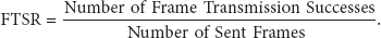
In order to evaluate the system performance, we need to define some parameters first. In the system, we use frame transmission success rate (FTSR) to define the transmission quality. The higher FTSR means the higher possibility to replicate captured frames to S-PNs. Therefore, the FTSR will decide whether the replication of video stream is success or not.
Definition 1 (frame transmission success rate (FTSR)).
Consider
4.1.1. Single Replica in the System
To evaluate the FTSR, we observe that there are some setting that will affect the FTSR: networking, capturing device's configuration, and node's processing speed. The networking setting includes bandwidth (Bw) and round-trip time (RTT) between peer nodes. The capture device's configuration consists of frames per second (FPS), frame size (FS), and the number of replicas (Ra). The node's processing speed includes the processing latency of copying streaming data from network device to memory
To deduce the FTSR, we need to define another three terms as follows.
Definition 2 (frame capturing time (Tc)).
The time to capture one frame: it is the reciprocal of FPS:

Definition 3 (frame processing time (Tp)).
The time to process each frame in the receiver: it is the FS divided by the node's processing time. Since the speed of NIC (network interface card) is faster than disk, we assume that the time
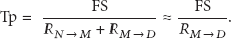
Definition 4 (frame transmission time (Tt)).
The time to transmit a frame to receiver:, in general, the Tt should be defined as FS/Bw. But a captured frame needs to be stored into local disk. Therefore, the Tt can be defined as the maximum of FS/Bw or Tp:

Tp is the time to store a frame to local disk.
Therefore, the FTSR including one replica can be replaced as follows:

4.1.2. Multiple Replicas in the System
If the system includes multiple replicas (S-PNs), the resource should be shared. Some equations need to be updated as follows.
Time of frame proceed


Therefore, the FTSR

4.1.3. Peer Node Channel Amount
Next we want to calculate the maximum number of channels (peer node channel amount: PCA) in a peer node. Because the network bandwidth is shared for all input and output channels in a peer node, the PCA will affect the FTSR. In other words, the higher PCA may result in the lower FTSR in a peer node. We assume that each frame has Ra replicas (including one P-PN and Ra-1 S-PN, by default the Ra is equal to 3). Therefore, a captured video frame will have Ra-1 output channel to S-PNs. Similarly, the peer node will have Ra-1 input channels from other P-PNs, since the peer node is serving as an S-PN of other nodes. In addition, the maximum concurrent clients to access and view video streaming are equal to the total number of replicas (Ra). Therefore, the maximum concurrent communication channels of a peer node are 3Ra-2.
4.2. Performance Evaluation
In this section we measure the FTSR to demonstrate the feasibility of the proposed system under various settings, which are the number of frames sent, bandwidth, FPS, frame size, RTT, and replica amount, respectively. While a parameter setting is varied, another parameter is kept constant. We implemented a prototype instead of using existing simulation tool to make the proof of concept and conducted some experiments to evaluate the performance. The DN is implemented using Ubuntu Linux 12.04 LTE on a duo core and 2 G RAM virtual machine. In the prototype, we also implemented three peer nodes: one for P-PN and two for S-PN; all are also run on Ubuntu Linux 12.04 LTE on a single core and 1 G RAM physical machine. All are connected using 100 Mbps Ethernet. All peer nodes are implemented in C language, and the OpenCV is used to control the camera recorder. Note that the frames captured and sent are flat data without any compression in all evaluations. If all frames are compressed before transmission, the impact will be lower than the result shown in this section. The following are to analyze the impact while varying parameter setting.
4.2.1. The Impact of the Number of Frames Sent
To evaluate and prove the system stability, we let the system fully run under the prototype with two replicas (S-PNs) and measure system's FTSR until 10000 frames are sent. The result is shown in Figure 4. In the evaluation, we can find that the average FTSR is 90%; it is not significant fluctuation with the amount of frame increasing. It means that there is 10% frame that will be discarded during video frame transmission. I think that the frame may be discarded because the buffer of receiver is full. The highest point is at 3000 frames, and the FTSR is 0.9227, while the lowest is at 7000 frames, and the FTSR is 0.8757. With more frames that have been sent, the system keeps working. In addition, we also run a client program to access the stored video; it shows that user can view the video streaming smoothly while the average FTSR is 90%. It is obvious that the system can be stably working.

Impact of number of frames sent.
4.2.2. The Impact of Network Bandwidth Variation
As mentioned in Section 4.1.3, the channel amount of a peer node will affect the FTSR, because the bandwidth is shared among the channels. The lower bandwidth limits the data transfer rate and affects the FTSR of the system. In the evaluation, we vary the network bandwidth and kept the same speed of frame capturing. The result shows that the FTSR descended with the bandwidth increasing, as shown in Figure 5. Obviously, the FTSR is limited by the bandwidth. If the bandwidth is large enough, for instance, 10 Mbps, it could not make any impact for FTSR. If the bandwidth decreased, the FTSR will descend. If the bandwidth is 5 Mbps, the FTSR is near to 0.88; it is acceptable.

Impact of network bandwidth variation.
4.2.3. The Impact of Network RTT Variation
Since the proposed system is scattered over large-scale network, such as wide area network, the round-trip time (RTT) between peer nodes may affect the FTSR between PNs. Here we try to discuss the impact of FTSR regarding RTT variation. In the evaluation, the RTT is varied from 0 to 100 ms. The result is shown in Figure 6. The FTSR is also fluctuating at 90%. It shows the RTT is not an important factor to FTSR. In the local area network, the RTT is almost 0 and its FTSR is 0.897510; while the RTT is increasing to 100 ms, the FTSR is 0.891384. The difference of various RTTs settings is small.
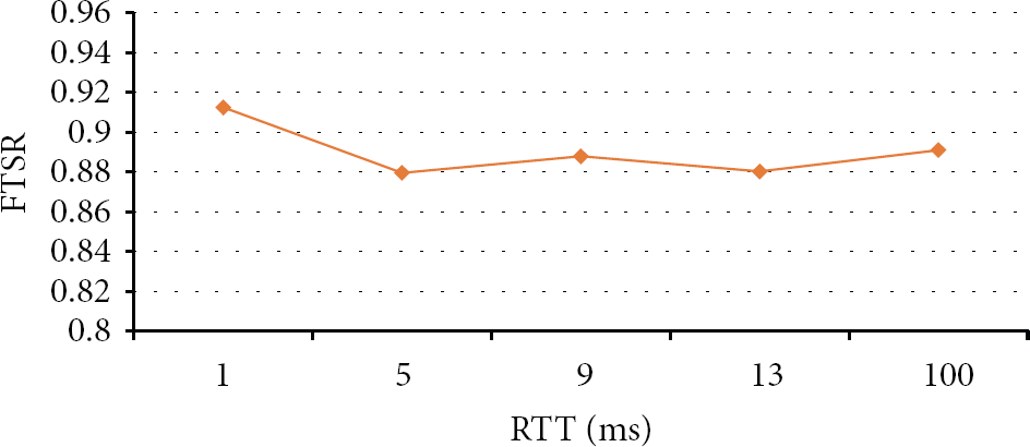
The FTSR with network RTT variation.
4.2.4. The Impact of Bandwidth and FPS Variation
Next evaluation is the impact of FTSR while concerning the bandwidth and FPS setting concurrently. The frequency of frame capturing by controlling webcam's FPS setting is adjusted and the bandwidth is varied. The result is shown in Figure 7. Here, x-axis represents the FPS. It shows that if the FPS is smaller, for instance, lower than 20 fps, the FTSR will be slightly affected by the bandwidth. It is acceptable for various bandwidth settings. When the FPS is at rate of 25 fps, the FTSR will be acceptable if the bandwidth is large enough, for instance, larger than 1 Mbps. If the FPS is larger than 30 fps, then the FTSR will be lower than 80% at various bandwidth settings. It may be not acceptable at various bandwidth settings. The lower bandwidth with higher FPS will lead to lower FTSR, because the frame transmission speed is lower than frame capturing speed.

Impact of bandwidth and FPS.
4.2.5. The Impact of Frame Size and FPS
Next evaluation is the impact of FTSR while concerning the frame size and FPS setting concurrently and keeping the bandwidth of network constant. We also adjust the frequency of frame capturing and frame size by controlling webcam's setting. The result is shown in Figure 8. Here, x-axis represents the FPS. The experiment evaluates five cases of frame size:

The FTSR with frame size and FPS.
4.2.6. The Impact of Number of Replicas and FPS
Finally, the experiment evaluates the impact of FTSR while concerning the number of replicas and FPS setting concurrently. If there are more replicas, the P-PN needs to transmit video streaming to all replicas; therefore, the total concurrent channels in the PN will increase, and the FTSR will be descended accordingly. By the default setting, two S-PNs are set to store video into other peer nodes. We can find the FTSR decreasing while the replica amount is increasing, as shown in Figure 9. If the Ra is 2 and the FPS is 25, then the FTSR is kept at acceptable rate of 90%.

The FTSR with replica amount and FPS.
4.2.7. Summary of the Evaluation
Some experiments have been conducted to evaluate the prototype. There are five important factors affecting the FTSR of the system: FPS, frame size, RTT, Ra, and bandwidth, respectively. Based on all evaluations, there are the following findings. First, if the FPS is smaller than 25, most of the experiments can obtain 90% FTSR. Second, the frame size is recommended to
4.3. Scalability Evaluation
The scalability is an important advantage of the proposed system. As mentioned above, the DN may be the bottleneck in a LVSS because it serves as a centralized data center. In the traditional system, the scalability depends on the hardware resource of centralized server, especially on the speed of hard disk drive (HDD). In the proposed system, the hardware resource of DN is not so critical because each PN connects to DN and is only at the first time to get other S-PNs’ location and their authentication keys. This section will make a scalability evaluation and comparison with other kinds of HDDs. We have surveyed a variety of HDDs and conducted experiments to evaluate the server usage while the server was utilizing these kinds of HDD and then make a comparison with the proposed system, as shown in Figure 10.
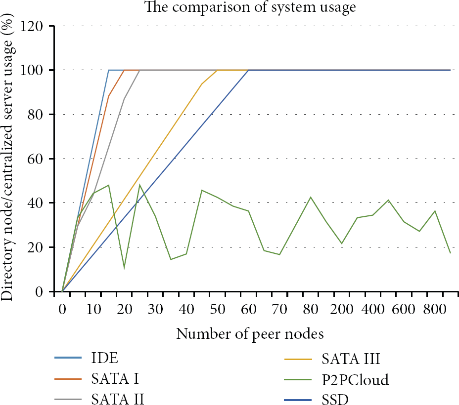
The comparison of system usage.
In the evaluation, the usage of centralized server will reach 100% while the server utilizes IDE as the interface of HDD and ties 14 PNs. In the same case, the server utilizes solid state drive (SSD), which is the fastest disk drive nowadays, and ties up to 60 PNs. In the proposed system, after tying 800 PNs, the average server usage is 30%. The reason is that all PNs only connect to DN at startup. Therefore, the usage of DN can keep low. The result shows that scalability of the proposed system is superior to others. Although there are a variety of techniques of data center storage, such as Microsoft's FDS [33], they will become a bottleneck while the number of PNs is significantly increasing because the resource, such as storage's space and network bandwidth, is limited.
5. Conclusion and Future Work
In this paper, we have proposed an architecture for video surveillance service by integrating P2P and Hadoop-like file system technology. Adapting P2P is used for locating and connecting with PNs for replication and delivering video streaming data to them. The evaluation and comparison have shown that the design can have the following advantages. First, the scalability can be improved because the data center is not a bottleneck yet. All video streaming of the system is stored into each PN and required bandwidth to data center can be significantly reduced. Second, the reliability can be enhanced due to replication mechanism used in the design (every video streaming backup into a replica group consisting of one P-PN and two S-PNs). While the P-PN or one of the replicas (S-PN) failed, the DN can select another PN to take over the fail. Third, the cost of data center also can be reduced. Although it will also increase the cost of individual PN, we think that this is trivial comparing with expensive data center. Besides, the robustness of the system can be guaranteed because a PN failure will not affect the service of the system.
In the future, we hope it can be implemented in real environment. In addition, the vehicle surveillance video recorder is usually installed on the car, but when the car accident happened, the recorder is sometimes destroyed and could not be recovered. In our system, we also hope to reorganize the system design and adopt mobile cloud, Cloudlet, to achieve the goal of vehicle surveillance video system based on P2PCloud.
Footnotes
Conflict of Interests
The authors declare that there is no conflict of interests regarding the publication of this paper.
Acknowledgments
This work was supported by National Science Council of Taiwan under Grant no. 102-2221-E-305-013- and 100-2632-H-029-002-MY3.