
Abstract
Air damping significantly influences the dynamical characteristics of MEMS accelerometers. Its effects at micro-scale level sharply depend on the structure layouts and size of MEMS devices. The damping phenomenon of comb microaccelerometers is investigated. The air between fixed plate electrodes and movable plate electrodes cannot flow freely and is compressed. The air damping, therefore, exhibits both viscous effects and stiffness effects. The former generates a drag force like that in macromechanical systems, and the damping force is proportional to the velocity of movable electrodes. The latter stiffens the rigidity of structure, and the stiffening level is related to the gap value of capacitors, internal pressure, and temperature. This paper focuses on the dependence of the squeeze film air damping on capacitor gaps. The simulation and experiments indicate that the squeeze film effect is sharply affected by the gap value when the structural dimensions decrease. And the influence of fabrication errors is considered in damping design in comb microaccelerometers.
1. Introduction
The aim of the mechanical design of MEMS devices is to acquire the desired dynamic behaviors (i.e., frequency response and quality factor). This achievement strongly depends on the damping phenomenon which strongly affects the movement of movable elements. Since damping limits the sensing accuracy of a given MEMS structure, a model relating structure parameters to the damping coefficients is critical to the system design and optimization.
Several successful analytical models of air damping of MEMS have been proposed. The review article written by Bao and Yang [1] deeply reported the progress of researches on the squeeze film air damping in MEMS. In the review, the basic effects of squeeze film damping on the dynamic performance of microstructures were discussed based on the analytical solutions to parallel plate problems including perforated plates, slotted plates, and torsion mirrors. Besides, Bao et al. [2] have proposed an energy transfer model for air damping in a low vacuum. This model can be used for calculating the quality factors of both the isolated oscillating plates and the oscillating plates with nearby electrodes. And the results of this model match the experimental data much better than those of Christian's model for a common rectangular plate. Many other authors have also analyzed the air damping in MEMS: squeeze-film damping behavior between plates [3] or perforated plates [4, 5], gas damping of micromirrors [6, 7], viscous damping of laterally oscillating microstructures [8, 9], and air damping of flexible microbeams [10–12].
In this paper, the damping in comb microaccelerometers is analyzed when the input acceleration is applied. Both the stiffening effects and viscous effects are considered when the capacitor gap changes with the fabrication errors including dimension variations and etching angles. The damping coefficients, the core features of damping, are acquired by simulation and experiments to study the damping phenomenon. The results have important significances on the dynamics design of MEMS devices consisting of comb structures.
2. Theory and Analysis
In mechanics of macromechanical systems, the damping effects can be replaced with a dashpot which provides a viscous drag as resistance force to a moving object. The damping force is related linearly to velocity and expressed as

where F
c
is the damping force caused by viscous drag effects, c is the viscous damping coefficient, and
2.1. Basic Theory
The sensing capacitors of comb microaccelerometers are comprised of two parallel rectangular plates between which the air gap is about few micrometers, and its cell can be represented by the diagram in Figure 1. When the movable plate is vibrating, the viscous effect is dominated in lower frequency zone and stiffening effect in higher frequency zone. And both effects coexist in the operation process of microaccelerometers. The coefficients of these effects can be expressed as those in [13], respectively:
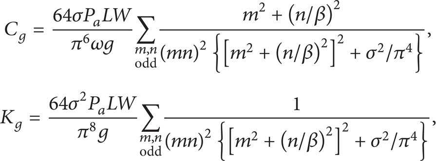
where C g and K g are the viscous damping coefficient and stiffness coefficient of air film, respectively; σ is the compression ratio of the squeeze film; P a is the pressure of air; L and W are the length and width of plate, respectively; β is the ratio of length and width, β = L/W; ω is the vibration frequency of movable plate; g is the gap of capacitor; m and n are constants, for a second-order system; and m = n = 1 is available [14]. The compression ratio representing the compressibility of air film can be expressed as

where μeff is the coefficient of effective viscosity, μeff = μ/(1 + f(K n )), and μ and K n are the coefficients of viscosity and Knudsen number, respectively [15].

The capacitor cell of comb microaccelerometers.
It is concluded from (2) that the levels of viscous effect and stiffening effect are different from one device to another and deeply depend on the structure dimensions and inner gas state. The inner gas state can be controlled or adjusted by a proper packaging process and its influence can be evaluated by a designed test or calibration. But the influence of dimensions is difficult to identify because the fabrication errors of microstructures are not easy to control due to the complication of etching processes. Besides, the dimension deviations induced by etching are comparable to the dimensions of beams and gaps of sensing capacitors in microdevices. Therefore, the damping effects of microstructures with limited fabrication errors are needed to be evaluated by numerical methods.
2.2. Model Analysis
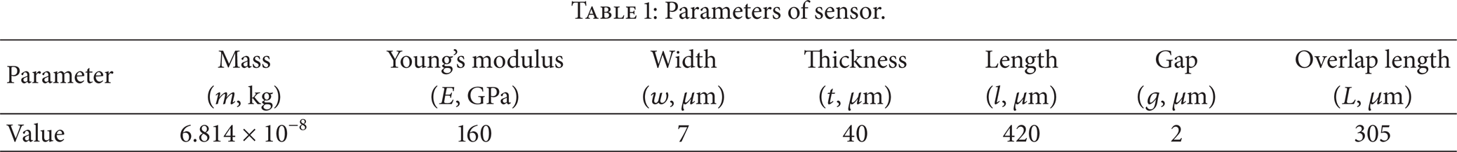
The comb capacitive accelerometers are proposed to study the damping effects in microdevices. The main sensor structure is depicted in Figure 2(a), which consists of mass block with movable fingers, folded-beams, and fixed fingers. The mass block is sensitive to the in-plane acceleration along input axis and moves under inertial force to change the gaps between movable fingers and fixed fingers which together form the sensing capacitors, whose cell is depicted in Figure 2(b). The differential capacitance formed by sensing capacitors is related to the gaps and can be handled by sensing circuits to reflect the value of input acceleration. The dynamical performance of the sensor involves the response of mass block to the external shock and vibration or instantaneous acceleration input. The parameters of sensor model are listed in Table 1, where symbols w, t, and l represent the width, thickness, and length of folded-beams, respectively; m is the mass of sensing block and g is the gap of sensing capacitor.
Parameters of sensor.

The sensor structure of comb accelerometer.
The stiffness and vibration frequency of mass block can be calculated as

where k is the total stiffness of four supporting folded-beams [16].
The chamber of sensor package is filled with nitrogen whose average molecular free path λ is equal to 60 nm and viscosity μ is 17.58 μPa·s under pressure of 1.01 × 10⁵ Pa and room temperature. And the K n belong to 0.001 to 0.1; the flowage of sensor fingers is slip flow according to [17]. When the fabrication error exists in gap and width of fingers, the coefficients of two damping effects are shown in Table 2.
Coefficients of two damping effects with fabrication error.
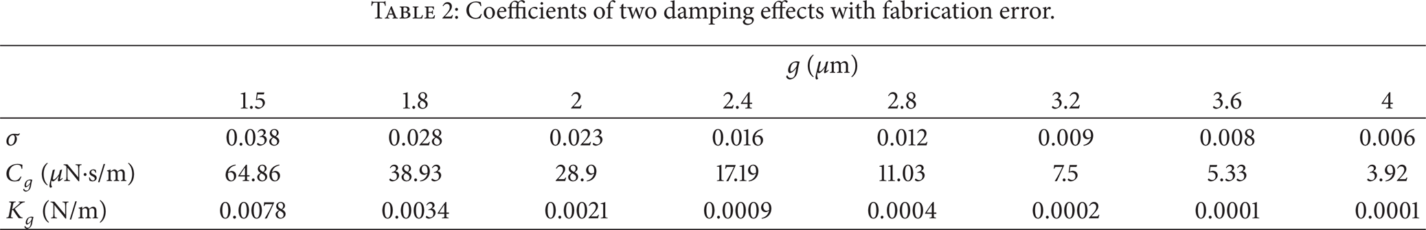
For the proposed model, the stiffening and viscous effects decrease sharply with the gap increasing from 1.5 μm to 2.4 μm although the viscous effect is always dominant due to the fact that compression ratio of gas σ is far smaller than 1 which indicates that the gas film is regarded as incompressible. The nominal dimension of capacitor gaps is designed as 3 μm. When the overetching or underetching error is present, the viscous coefficient and stiffening coefficient can be determined by (2). The etching angle error induced by DRIE (Deep Reaction Ion Etch) process is another error in the proposed model needed to be considered in damping design, and its influence is very important to the damping effect which is carried out in the following section by simulation.
3. Simulation and Experiment
The damping coefficient of microaccelerometer gained in dynamical test is a comprehensive result from inner gas state, dimension errors, temperature and humidity, and so forth. Since the absence of accurate measuring technologies makes it impossible to acquire the real structural parameters of sensing capacitors, the COMSOL software and whole sensor tests are proposed in this paper to study the dependence of damping coefficients on the fabrication errors including dimension deviation and etching angle.
Dimension deviations induced by overetching or underetching result in a changed gap of capacitors formed by fixed fingers and movable fingers. Figure 3 gives the damping coefficients of left half part of sensor model in Figure 2(a) with capacitor gap from 1.5 μm to 4 μm. It shows a sharp decrease of coefficients in the narrow gap zone; the variation from 1.5 μm to 2.4 μm is about 48 μN·s/m, almost four times that from 2.4 μm to 3.6 μm. The difference between analytical results and simulation results is caused by the omitted influence of the tangential damping of fingers in analytical method. Because the direction of air flow in gap when the movable fingers move close to the fixed fingers is opposite to that of reversed movement, the damping coefficients of above two movements have a slight difference and the former is a little larger due to the stiffening effects. Figure 4 gives the damping coefficients of 3 μm gap model under different acceleration input in both “close” direction and “away” direction. The difference of coefficients increases with increasing acceleration and the damping coefficient of “close” direction also has the same tend, but that of “away” direction decreases with increasing acceleration.
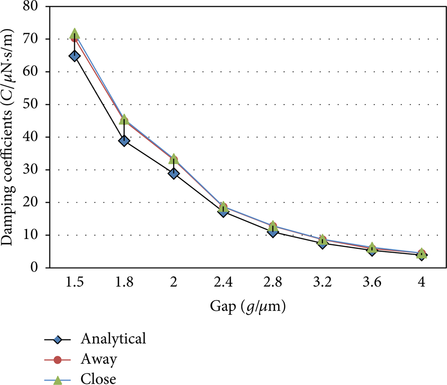
Damping coefficients vary with gaps.

Damping coefficient differs from one direction to another.
The etching angle is another important fabrication error in deep-reaction-ion-etching (DRIE) process [18]; its influence on the damping coefficients is depicted in Figure 5, which indicates that the damping effects are little affected by the angle errors due to the fact that the flow route variation is very small under such a small slope angle. The damping coefficient descends with angle's increasing due to the increase of the efficient thickness of air film between capacitor plates.

Damping coefficients vary with etching angles.
The experiment of this study is based on comb microaccelerometers fabricated by DRIE process and anodic bonding technology, and the fabrication step details can be found in [16]. The damping coefficients of ten sensors with designed 3 μm gap have been tested by free decay method on the dynamic measurement equipment shown in Figure 6(a). The damping coefficient is about 21.88 μN·s/m of designed sensor, which is as twice as the theoretical value of the above half model. The comparison curves of damping coefficients are depicted in Figure 6(b); all the tested values are larger than designed values because the latter consists of damping effects formed by capacitor fingers and mass block which is a solid rectangular with lots of square through-holes shown in Figure 7. The viscous effect of the mass block is about 1.3 μN·s/m based on simulation in COMSOL software; therefore, the tested values resulting from the fingers are smaller than designed values because of the overetching error which is about 0.2 μm in empirical value. It is concluded that the theoretical value has a good agreement with experimental value of comb microaccelerometers.

The measurement equipment and test results.
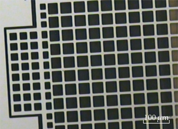
SEM of solid rectangular with lots of square through-holes.
4. Conclusion
The damping coefficients, as an important parameter in microstructures design, significantly influence the dynamical behaviors of microdevices. The damping characteristics in microscale level, however, are not the same as those in macroscale level but intensely depend on the natural frequency and dimensions of microstructures due to the coexistence of both the viscous effects and stiffening effects. The sensor model is established to verify the damping effects of the proposed accelerometers in this paper. It is indicated that the viscous effect is also the main damping factor when the accelerometers are under external shocks. The damping coefficient is extracted to represent the viscous damping effect of comb capacitors of microaccelerometer, and its dependence on fabrication error is studied by both simulation and experiments. The identical results indicate that the damping coefficient decreases with the capacitor gap's increasing, and it decreases sharply when the gap value is less than 2.4 μm. The etching angle whose value is less than 1 degree, however, has little influence on the damping effect of microaccelerometers.
Conflict of Interests
The authors declare that there is no conflict of interests regarding the publication of this paper.
Footnotes
Acknowledgments
This research was partially supported by National Natural Science Foundation of China (Grants nos. 51175437 and 91123023), Fundamental Research Funds for the Central Universities (Grant no. ZYGX2011J085), and Jiangsu Key Laboratory of Meteorological Observation and Information Processing, Nanjing University of Information Science and Technology (no. KDXS1109). The authors would like to acknowledge Zhang Fengtian, Shi Zhigui, and Du Lianming for their assistance in fabrication and experiments.