
Abstract
Thin plates with a thickness of 1.2 mm are fabricated using two processes, thixoforging and rheoforging, which are semisolid forming techniques. The die design, formability, microstructure, and mechanical properties of the fabricated thin plates are analysed. A fan-shaped gate is designed by analysing the filling behaviour using semisolid material, and uniform filling behaviour of material is obtained by arranging nine overflows in product area. semisolid metal is prepared through a semisolid process in which reheating, a thixoprocess, and cooling with stirring, a rheoprocess, are applied. The semisolid material is injected into a forging die and is formed into thin plate at a punch speed of 300 mm/s and under a pressure of 100 MPa. Since semisolid material with a solid fraction below 45% has mainly small primary α-Al particles, the formability of the thin plate is improved. The formed thin plate also has good mechanical properties since the small and globular grains are evenly distributed. The thin plate formed from semisolid material with a solid fraction above 50% has poor mechanical properties owing to the large quantity of coarse primary α-Al particles. A rheoforged thin plate exhibits poorer mechanical properties than a thixoforged thin plate, but rheoforging produces a more precise thin plate.
1. Introduction
Semisolid forming is a complex metal-forming process in which solid-state and liquid-state materials coexist and the merits of casting and forging are combined. Because deformation resistance is lower in this process than in conventional forging, in which solid-state material is used, parts with complex shapes can be fabricated using only one process. As the viscosity of a semisolid material is higher than that of a liquid-state material, the flow becomes uniform when it is filled into a die, thus leading to lower heat fatigue on the die than when liquid material is used. Besides, short shot (misrun or no filling) occurs less frequently and less gas or fewer void defects are generated. Moreover, there are fewer defects caused by shrinkage because the material is formed while it solidifies, which enables production of high-density precision products. In particular, the size of primary particles is controlled in semisolid material, allowing them to form a dense and uniform structure that results in improved mechanical property of the product [1–10].
Since semisolid forming was first proposed by Flemings et al. in 1976, many research studies have been conducted on the technique [11]. The process is divided into two categories: thixoforming and rheoforming. In thixoforming, a billet prepared by stirring is reheated until it reaches the semisolid state; in rheoforming, a liquid-state material is cooled to the semisolid state as it is stirred during solidification [12–15]. With thixoforming, uniform grains and high mechanical strength could be attained. However, thixoforming faces the problems of high cost of the feedstock billets used as raw materials and the reheating process [16–18], while rheoformed products have the disadvantage of defects resulting from gas and impurities that enter the semisolid slurry during stirring. Moreover, the mechanical properties of a rheoformed product are not constant owing to the irregular grain distribution by liquid segregation [19–21]. So far, research studies on semisolid forming have mainly focused on resolving the above problems in large-sized parts for automobiles or airplanes, while research on semisolid forming for thin-plate parts has not been carried out. Therefore, the objective of this study is to fabricate thin plates (thickness: 1.2 mm) into which a channel with a concavo-convex cross section is inserted by thixoforging and rheoforging. This type of thin plate with an inserted channel can be used as a fuel-cell bipolar plate, in plate heat exchangers and in electronic components. A design for the die required for thin-plate production, thixoforging, and rheoforging is proposed; the formability, microstructure, and mechanical properties of the formed thin plate were investigated and the results are reported here.
2. Die Design
A die was designed for this study. To form a thin plate using the semisolid process, material is pressed on the die and then pushed into the die cavity while the upper and lower dies are closed. The die cavity comprises a sleeve (biscuit) into which semisolid material is injected, a gate through which material flows into the product area, a product area into which the material is filled and overflows to promote smooth filling of the material in the cavity. Figure 1 shows the shape of the cavity in the die for thin plates, designed using results of a die-filling analysis. The product area measures 150 mm in length and width and 1.2 mm in thickness.

Geometry of die cavity for thin plate with channels (unit: mm).
The gate is a passage in which the pressure energy (energy per unit volume) of the semisolid material is converted into kinetic energy per unit volume, and it is an entry port for the filling material into the product area. The gate should be adequately designed according to the shape of the product area because the filling behaviour of the material changes with the shape of the gate. The dependence of a semisolid material's filling behaviour on the gate geometry was analysed through filling analysis of the die to ensure uniform filling of the semisolid material into the product area. The material used for this study was the aluminium alloy A356, and the A356 thixomodule of MAGMA (MAGMA Giessereitechnologie GmbH, Germany) was used for simulation of the material's filling behaviour. The conditions and heat-transfer coefficient used during the simulation are presented in Table 1. Figure 2 shows the simulated filling behaviour expressed as the temperature distribution for a straight gate model and a fan-shaped gate model. In the straight gate model (Figure 2(a)), the centre of the product area was filled first, along the shape of the gate owing to the effect of viscosity. At the side of the product area, the filling was executed by backflow of the material that returned after touching the end of the product area. With this type of filling behaviour, there is a high possibility of short shot at the side because the material solidifies rapidly in the thin cavity under actual casting conditions. Therefore, the gate was extended in the shape of a fan in the second model so that the material could spread over the entire surface of the product area while moving forward simultaneously. Figure 2(b) shows the filling behaviour in the fan-shaped gate model; the material filled the entire product area after passing through the gate.
Simulation parameters for semisolid forging.

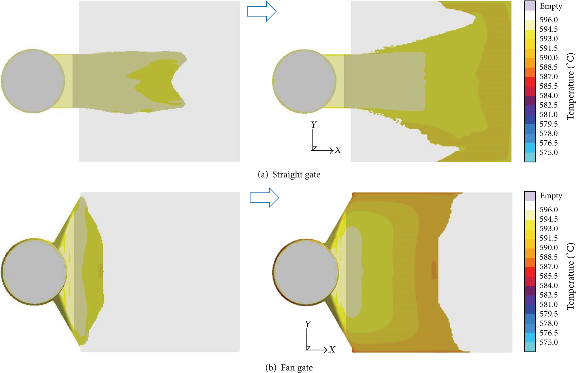
Comparison of the material filling behaviour (temperature) (a) straight gate model and (b) fan gate model.
After the gate shape design was finalized, a channel with a concavo-convex cross section was inserted into the product area. Such channels can serve different purposes in various applications. For example, the bipolar plate channel of a fuel cell allows the flow of the reaction gas, while cooling water flows through the channel of a plate heat exchanger. As can be seen in Section A-A in Figure 1, a groove was created as a channel, while the protrusion part consisted of ribs. The depth and width of the channel were 0.3 mm and 1.0 mm, respectively, and the channel had the shape of a trapezoid with 20° slopes on both sides. Active area of channel with serpentine shape was 70 mm in both width and length. Figure 3 shows the simulation results for model 1, where a channel was inserted in the product area. In the temperature distribution plot shown in Figure 3(a), after the material completely filled the product area, it solidified at <577°C (red colour) at the side and end and in the channel. Figures 3(b) and 3(c) show the results of the material age (elapsed time of material inflow: longer time indicates that the material had flowed into the product area earlier; shorter time indicates that the material entered later) and air-contact time (the time when the material made contact with air or gas). The site with high material-age value was the location at which a relatively large amount of material was solidified so that short shot of material became highly possible. Meanwhile, void defects could easily form at the site with high air-contact time. It was confirmed that the material age and air-contact time were abruptly increased because of irregular flow of material when it passed through the concavo-convex channel.

Simulation results for model 1 (with channels) of temperature, material age, and air contact.
Overflow plays an important role in controlling a material's flow and casting defects. As can be seen in Figure 1, there are five overflows at location 1, which is the end portion of the product area, and there are four overflows at location 2 at the side of the product area. These overflows were arranged based on the simulation results shown in Figures 3–6. Each overflow at location 1 served to remove gas and impurities produced during solidification on the surface of the semisolid material and punch compression of the semisolid material flowing into the cavity. As confirmed by the simulation results of the material age and air-contact time in model 2, the high values for both are removed by the overflows at location 1 (Figure 4). The overflows at location 2 were designed to maintain a uniform filling speed as well as high and uniform pressure on the material. The material filling behaviour in the fan-shaped gate model, as shown in Figure 2(b), implies that the material flow rate was faster at the side than in the centre. The material with fast flow rate at the side ran into overflows at location 2 so that a uniform filling speed was secured (Figure 5). Figure 6(a) shows the pressure distributions of model 3 with overflows at location 2 and model 2 without overflows at location 2. In the latter, the material pressure was abruptly reduced while the material passed through the channel, especially at the entry points of overflows at location 1, where the pressure was lost as it was vented to atmosphere pressure (light blue portion in figure). It is possible that the material was not filled uniformly until it reached the entry points of overflows at location 1. Therefore, overflows were arranged at location 2 in model 2 so that the high pressure near the gate (yellow portion) could be maintained at the end of product area. The pressure distribution (Figure 6(b)) of model 3 with overflows at location 2 shows that high pressure was maintained until the end portion of the product area and uniform pressure could also be achieved throughout the part.

Simulation results for model 2 (with channels and overflows in position 1) of material age and air contact.

Comparison of the velocity (a) model 1 without overflows in position 2 and (b) model 3 with overflows in position 2.

Comparison of pressure (a) model 2 without overflows in position 2 and (b) model 3 with overflows in position 2.
Figure 7 shows the filling behaviour of the semisolid material expressed as a temperature distribution for the model based on the simulation results. The material filling was uniformly executed between the gate and overflows.

Simulation results for final model of material filling behaviour.
3. Forming Process
3.1. Preparation of Semisolid Material—Reheating of Billet (Thixoprocess)
A billet of the A356 aluminium alloy (diameter: 50 mm) was used as the semisolid material. The liquidus temperature of A356 is 617°C and its solidus temperature is 547°C. In the thixoprocess, a solid-state material is heated to transform it into the semisolid state. Reheating of the billet to prepare the semisolid material was executed inside a horizontal high-frequency induction-heating system, as shown in Figure 8, after the billet was cut into 100 mm pieces.

Reheating process for fabricating semisolid slurry-thixoprocess.
The initial solid feedstock was placed inside a slurry cup before the rapid-heating experiments. The slurry cup was made of a nonmagnetic material, and it had internal and external diameters of 52 mm and 58 mm, respectively. A high-temperature lubricant made of boron nitride was sprayed on the interior of the cup, and the lubricated slurry cup facilitated handling of the semisolid slurry into the die. Rapid-heating experiments were performed using the induction-heating system with 80 kW capacity. The billet pieces were heated to temperatures of 585°C, 590°C, and 600°C, which yielded solid fractions of approximately 50%, 45%, and 35%, respectively. Hereafter, these semisolid materials are referred to as thixo billet-50% fs, thixo billet-45% fs, and thixo billet-35% fs. The rapid-induction-heating rate was 140°C/min, the semisolid slurries were held isothermally for 20's at each temperature, and the total heating time was less than 300's and depended on the final heating temperature. In order to measure the temperature during the rapid-heating process, a hole was machined into the axis of each billet piece for a thermocouple and a K-type thermocouple with a diameter of 1.6 mm was inserted into this hole. When the desired heating condition was obtained, the thermocouple was removed and the semisolid slurry was transferred into the die for thixoforging. The total time taken to transfer the material from the heating system to the press machine and to complete thixoforging was 7–10's. It was estimated that the temperature of the semisolid slurry was only 1–1.5°C below the designed thixoforging temperature.
3.2. Preparation of Semisolid Material—Solidification of Molten Metal Using Electromagnetic Stirring (Rheoprocess)
Semisolid material was prepared using an A356 ingot with the same chemical composition as that of the A356 billet used in the thixoprocess. A rheoprocess is a method that transforms molten material into the semisolid state by cooling. During cooling, electric stirring of the molten material was executed with an electromagnetic stirrer (EMS) to form a fine microstructure in the semisolid state. The preparation process is shown in Figure 9. After the A356 ingot was inserted in the electric furnace, it was melted at 720°C. The molten material was then transferred into a cup with a ladle, the EMS was inserted, and the molten material was stirred as it turned into a semisolid.
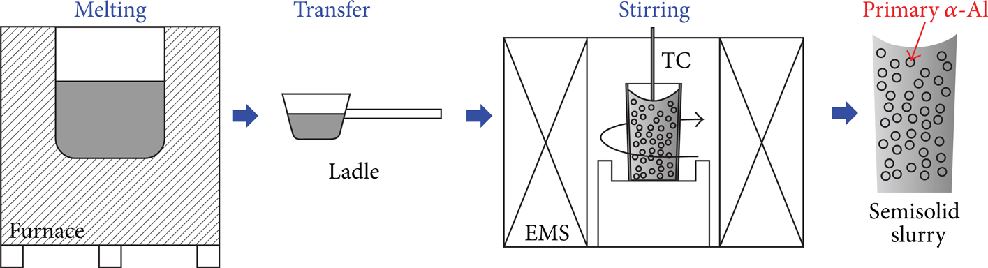
Electromagnetic stirring process for fabricating semisolid slurry-rheoprocess.
The EMS is a horizontal stirrer with three power levels. By inserting the coil vertically to the core, the stirring force was generated in the circumferential direction by the electromagnetic force. This stirring force controlled the size of grains in the material by restricting the growth of irregular grains that were generated during solidification while the molten metal rotated. It also controlled the coarse growth of aluminium grains that adhered to each other. In addition, the shape of grains became globular partially owing to the local shear force.
As the stirring current increased, the stirring speed for the molten material grew faster. A current that was too low could make stirring impossible as solidification of the material progressed, while an excessively high current could cause overflow of the material out of the cup as well as aggregation of primary α-Al particles. Therefore, the stirring current was set at 60 A, and the temperature of the molten material was set at 620°C for the stirring. The semisolid materials were thus prepared at 600°C with a solid fraction of 35%, at 590°C with a solid fraction of 45%, and at 578°C with a solid fraction of 55%. Hereafter, these semisolid materials are referred to as rheo slurry-35% fs, rheo slurry-45% fs, and rheo slurry-55% fs.
3.3. Preparation of Thin Plate—Forging Process Using Semisolid Material
A schematic of the forging process for thin-plate production using semisolid material is presented in Figure 10. A forging die was fabricated using the same method for die casting of precision products. After the semisolid material was injected into the sleeve of the die while the upper and lower dies were closed, it was compressed by a punch and filled into the die cavity. The speed of the punch was set at 300 mm/s, while the punch pressure was set at 100 MPa. The compression was maintained for 5's to allow the semisolid material to solidify under pressure. Since a semisolid material has a thixotropic character, its viscosity is considerably increased under shear force. When the material is compressed with a punch, sticking of material frequently occurs on the edge of the die cavity and sleeve surface. Therefore, in our study, graphite lubricant for hot forging was applied on the sleeve and cavity to prevent sticking, and it moved along with the semisolid material and gathered into the overflows. The forging die was then placed in a hydraulic press with a capacity of 200 tons (t), where it was heated by a cartridge heater and the die temperature was maintained in the range of 280–300°C. Because the forged thin plate could be deformed by the ejector pin, it was removed after waiting for 10 s while the upper die was opened.

Forging process with semisolid material.
Thin plates were fabricated by forging semisolid materials prepared via both thixo- and rheoprocesses. The formability, microstructure, and mechanical properties of these thin plates were then analysed.
4. Experiment Results
4.1. Formability
The thin-plate samples fabricated by forging semisolid materials prepared by thixo- and rheoprocesses are presented in Figure 11. For the material with a solid fraction of 55% prepared via the rheoprocess, rheo slurry-55% fs, short shot (incomplete filling of material in the die) occurred in the region that was connected to overflows at location 1 (indicated by an arrow). Under the five remaining process conditions, all the product areas were properly formed (the die was completely filled with the semisolid material). The pressure abruptly dropped around overflows at location 1, as shown in the simulation results for the pressure distribution in Figure 6(b). As expected based on the simulation results, in the photos of the actual formed samples (Figure 11), short shot was observed at overflows at location 1 of each sample that was formed from semisolid materials with high solid fraction (thixo billet-45% fs, thixo billet-50% fs, rheo slurry-45% fs, and rheo slurry-55% fs). The higher the solid fraction, the lower the formability regardless of the preparation process (thixo- or rheoprocess) for the semisolid material. The thin plates prepared with materials with a solid fraction of 35% (T = 600°C) were perfectly formed until they reached the overflows, while the thin plates formed from materials with solid fractions above 45% (T = 590°C) had short shots at overflows at locations 1 and 2.

Thin plates fabricated by (a) thixoforging and (b) rheoforging.
Figure 12 shows the dimensions of the fabricated thin plates: Figure 12(a) shows the thickness (t) of thin plates at nine locations, while Figure 12(b) shows the channel depth at nine locations. The thickness of the product area was 1.2 mm and its channel depth was 0.3 mm, as shown in the cross section of the die cavity in Figure 1. It could be confirmed that the thickness of the sample decreased along the direction of material filling (i.e., farther from the gate) for all thin-plate samples fabricated under six forming conditions. The regions near the gate (A1, B1, and C1) were thicker than those at other locations, while the regions around entry points of overflows at location 1 (A3, B3, and C3) were relatively thin. The thickness of the thin plate fabricated from rheo slurry-35% fs was closest to the thickness of die cavity; this was determined to be the forming condition that yielded the most precise product. As the solid fraction increased, the thickness of the thin plate became higher than that of the die cavity because the flow rate of primary α-Al particles was lower than that of liquid phase. The flow rate of semisolid material became far lower as primary α-Al particles were coarsening and were irregular, and flow rate of material became further reduced. If a material with high solid fraction is compressed, the coarse primary α-Al particles cannot move forward smoothly because of the pressure, and they are filled into the cavity at the instant when both the upper and lower dies are opened. This was how a plate thicker than the die cavity was formed. The thin plate fabricated by the thixoprocess was thicker than the thin plate fabricated by the rheoprocess. The channel depth showed the same trend as thickness of thin plate; that is, as the thickness of the thin plate increased, the channel depth increased.
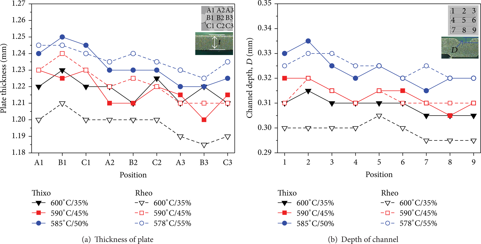
Dimension of thixoforged and rheoforged thin plate: (a) thickness of plate and (b) depth of channel.
4.2. Microstructures
The microstructure was measured at the centre of the channel in the fabricated thin plate. The microstructures in the thin plates fabricated under six types of process conditions are presented in Figure 13. The size of the primary α-Al particles was small as the solid fraction of the semisolid material was reduced, and its distribution was uniform in both thixoforged and rheoforged plates. In materials with a solid fraction of 35%, the number of primary α-Al particles was higher and they were distributed more evenly in the rheoforged thin plate than in the thixoforged thin plate. On the other hand, for the materials with a solid fraction of 45%, more small-sized primary α-Al particles were distributed in the thixoforged thin plate than in the rheoforged thin plate. The thin plate fabricated by forging thixo billet-50% fs had more primary α-Al particles with uniform distribution than in the thin plate prepared from rheo slurry-55% fs.

Microstructure of (a) thixoforged thin plates and (b) rheoforged thin plates.
Figure 14 presents the quantitative results of size, roundness, and fraction of primary α-Al particles in the thin plates fabricated under six types of process conditions. As the shape of primary α-Al particles became more and more globular, the roundness value approached 1. As the shape of primary α-Al particles became more irregular, the roundness value approached 0. The lower the material's solid fraction, the smaller the primary α-Al particles and the closer the roundness to 1. In general, the thin plate fabricated by rheoforging had smaller primary α-Al particles with almost globular shape than those in the thixoforged thin plate. The smallest size of primary α-Al particles with roundness near 1 was obtained when semisolid material with a solid fraction of 35% was used in both thixoforging and rheoforging. The size and roundness of primary α-Al particles in the thin plate fabricated by forging rheo slurry-35% fs were 69 μm and 0.9, respectively. Meanwhile, the size and roundness of primary α-Al particles in the thin plate fabricated by forging thixo billet-35% fs were 76 μm and 0.87, respectively. The volume fraction of primary α-Al particles was higher in the thin plates fabricated by forging rheo slurry-35% fs and rheo slurry-45% fs than in plates formed by forging thixo billet-35% fs and thixo billet-45% fs. It was confirmed that the volume fraction of primary α-Al particles inside the thin plate increased with solid fraction until the latter reached 50% in the semisolid material. However, if the solid fraction exceeded 50%, the distribution of primary α-Al particles inside the thin plate decreased instead. This result implies that mostly smaller-sized primary α-Al particles were distributed in the materials with 35% solid fraction. In addition, as smaller grains could move faster than larger ones, it was beneficial for smaller grains to move into the die cavity while the semisolid material was compressed. On the other hand, the semisolid materials with solid fractions above 50% had more coarse primary α-Al particles than the materials with 35% solid fraction and the movement of the coarse particles was poor, resulting in fewer primary α-Al particles inside the thin plates. However, because the size of the coarse grains was higher, the volume fraction of primary α-Al particles was the same as that of the thin plates made of materials with a solid fraction of 35%. In other words, when the solid fraction became more than 50% in the semisolid material, the primary α-Al particles became coarse and were prone to connect with each other. Because these rough primary α-Al particles and connected grains had less fluidity, it was difficult for them to move into the die cavity. Therefore, when the semisolid material with solid fractions above 50% was compressed, the liquid phase would have filled the cavity more completely and evenly than the coarse primary α-Al particles.

Variation in average grain size, roundness (shape factor), and fraction of primary particles.
4.3. Mechanical Properties
Tensile tests were performed on the specimens prepared from three thixoforged thin plates and three rheoforged thin plates. The specifications for the sample were designed according to the plate-shaped sample in ASTM E 8M (subsize); the gauge length was 25 mm and the width was 6 mm. The thickness of the test specimens was the same as that of formed thin-plate samples. During the tensile tests, 25 t of MTS was used with a strain rate of 1 mm/min.
The tensile strength and elongation values of the thin plates fabricated by thixoforging and rheoforging are presented in Figure 15. The thin plates fabricated by thixoforging exhibited increasing tensile strength and elongation as the solid fraction decreased in the semisolid materials. On the other hand, the rheoforged thin plates showed increasing tensile strength until the solid fraction reached 45%, but it decreased at a solid fraction of 55%. The tensile strength and elongation were the highest at 177 MPa and 5.5%, respectively, for the thin plate formed by forging rheo slurry-45% fs, while the thin plate formed from rheo slurry-55% fs showed the lowest tensile strength (160 MPa) and elongation (3.0%). Generally speaking, the tensile strength and elongation of thixoforged thin plates were higher than the values obtained for rheoforged thin plates. The difference in the tensile strength and elongation became reduced as the solid fraction became higher in the semisolid material. The highest tensile strength and elongation of 268 MPa and 10.5%, respectively, were obtained for the thin plate fabricated by forging thixo billet-35% fs. The tensile strength of the thin plate formed by forging rheo slurry-35% fs was 170 MPa and the elongation was 5.5%, 98 MPa, and 5.0% lower than the values obtained for the thin plate forged from thixo billet-35% fs. The tensile strength and elongation of the thin plate forged from thixo billet-45% fs were higher by 83 MPa and 2.0% than the values for the thin plate forged from rheo slurry-45% fs. The tensile strength and elongation of the thin plate forged from thixo billet-50% fs were 225 MPa and 2.5%, respectively, while the tensile strength and elongation of the thin plate forged from rheo slurry-55% fs were 160 MPa and 3.0%, respectively. Even though material with 5% higher solid fraction was used in the rheoforged thin plate than in the thixoforged thin plate, the tensile stress was lower by 65 MPa. However, the elongation was 0.5% higher in the rheoforged plate than in the thixoforged plate. Since materials with solid fractions below 45% had smaller and more globular primary α-Al particles, the thin plates formed from these materials showed small globular primary α-Al particles that were densely distributed. In contrast, the materials with solid fractions above 50% included irregular and coarse primary α-Al particles. The fluidity became low when each of the materials was compressed by the punch so that it would have been difficult for the particles to move inside the die cavity. In the formed samples, relatively large primary α-Al particles were distributed and a high proportion of the liquid phase was present. Therefore, thin plates formed from materials with solid fractions of 35% and 45% that contained large amounts of globular small grains showed high mechanical strength.

Tensile properties of thixoforged and rheoforged thin plates.
5. Conclusion
(1) In a die designed to fabricate thin plates using a semisolid forming process, the material is compressed and pushed into the die cavity while the upper and lower dies are closed. A fan-shaped gate is beneficial to even filling of the material into the die cavity, and uniform material filling behaviour can be obtained when overflows are located at the side and opposite to the gate.
(2) There was no short shot in the thin plates formed from semisolid materials with a solid fraction of 35%. Short shot was found at overflows in the thin plates formed by forging thixo billet-45% fs and rheo slurry-45% fs, and short shot occurred in the thin plate formed by forging rheo slurry-55% fs. A thin plate could be formed more precisely through rheoforging than thixoforging when the material had a solid fraction below 45%. The thin plate formed by rheoforging of material with a solid fraction of 35% did not generate any defects and its shape was almost the same as the die cavity.
(3) As the solid fraction was increased in a semisolid material, the primary α-Al particles became coarse and the grain distribution grew uneven. With thixoforging, if material with a solid fraction of 45% was used, a denser and more uniform thin plate could be obtained. With rheoforging, fine and uniform distribution of grains was observed in the thin plates formed from materials with solid fractions of 45% and 35%. The thin plates fabricated by rheoforging had smaller and more globular primary α-Al particles than those in thin plates fabricated by thixoforging, and many primary α-Al particles were evenly distributed in the rheoforged thin plates.
(4) Higher tensile strength was measured in the thin plates fabricated by thixoforging; when compared to the rheoforged thin plates, the difference in tensile strength was reduced as the solid fraction increased in the thin plates prepared by thixoforging. The mechanical property of a thixoforged plate was improved with decreases in the material's solid fraction. The highest tensile strength of 268 MPa and elongation of 10.5% were obtained in the thin plate forged from a thixoprocessed material with a solid fraction of 35%. Meanwhile, the rheoforging process yielded the highest tensile stress of 177 MPa and elongation rate of 5.5% when material with a solid fraction of 45% was used.
Conflict of Interests
The authors declare that there is no conflict of interests regarding the publication of this paper.
Footnotes
Acknowledgments
This work was supported by the National Research Foundation of Korea (NRF) Grant funded by the Korea Government (no. 2013R1A1A2062759). This study was also supported by human resources development of the Korea Institute of Energy Technology Evaluation and Planning (KETEP) Grant funded by the Korea Government, Ministry of Knowledge Economy (no. 20104010100540). This study was also supported by the National Research Foundation of Korea (KRF) Grant funded by the Korea Government (MISP) through GCRC-SOP (no. 2012-0001204).