
Abstract
This paper deals with the kinematic calibration and motion control of a triple-level spatial positioner consisting of the cable-driven parallel manipulator (CDPM), active gyro stabilizer (AGS), and the Stewart platform. A six-degree-of-freedom laser tracker is employed when calibrating the benchmark positions and measuring the real-time position and orientation in motion control, which makes it a straightforward solution to tackle with hierarchical mechatronic system actuated by servomotors with incremental encoders. Then the trajectory planning and motion control of the triple-level robotic spatial positioner are explored to verify the correctness and to what extent the calibration improves the system. This CDPM based spatial positioner has an accuracy of several millimeters though it has a ten-meter workspace.
1. Introduction
The five-hundred-meter aperture spherical radio telescope (FAST) is being built in the limestone formation in China [1, 2], which will be the largest single dish super antenna of the world, thus being endowed with revealing the mystery of the universe. One of the prominent innovations of FAST lies in its triple-level spatial positioner for supporting the feed (the radio waves receiver). This triple-level robotic system integrating optical, mechanical, and electronic technologies for the feed supporting structure effectively reduces its weight and cost [3, 4].
As shown in Figure 1, the six steel cables driven by servomotors and winches are the limbs of the first level cable-driven parallel manipulator (CDPM), with the semispherical cabin as the end effector. The second level subsystem is the servomotor driven active gyro stabilizer (AGS), and the third level Stewart platform is mounted on the bottom of the AGS. The trajectory for the feed when observing a radio target will be as large as a circle with the radius of 186 m and height of 150 m, but real-time RMS of positioning and orientating error for the feed must be less than 4 mm and 8 arc minutes, respectively [1]. Consequently, the goal of this spatial positioner application is to provide both a large manipulating workspace and high accuracy of the feed.

Overview schematic of the triple-level spatial positioner for FAST.
From the robotics point of view, a considerable amount of research including calibration and motion control has been done on the rigid six-degree-of-freedom parallel manipulator in the case of that the base is fixed. Zhuang and Roth proposed measurement procedures for calibration of Stewart platform to improve the kinematic model [5]. Zhuang presented the self-calibration of parallel mechanism and by using redundant sensor [6]. Khalil and Besnard studied self-calibration of Stewart-Gough parallel robots without extra sensors [7]. However, to the authors’ knowledge little work on two variants of parallel manipulator has been done. One is the large-span cable instead of rigid extendable driven parallel manipulator. The other is a parallel manipulator mounted on a compliant base like the application in this research. Qiu et al. proposed the output torque-based indirect initial length calibration of a cable-driven parallel manipulator [8]. Since all the actuators for the CDPM, AGS, and Stewart platform are position closed-loop motors, the precision of this triple-level spatial positioner depends to great extent on the accurate kinematic models comprising the individual models of the three subsystems and the kinematic model among them. Therefore, the calibration of the triple-level spatial positioner is of great importance for accomplishing the astronomical goals of this super antenna. Besides, choice of calibration method is closely involved with measuring equipment. This paper presents the calibration with multi-degree-of-freedom optic measurement and servo amplifier as auxiliary.
The remaining of this paper is organized as follows. Section 2 gives an overview description of the CDPM based triple-level spatial positioner with emphasis on hardware configuration (no intention of the authors to advertise any product); Section 3 presents the kinetostatic calibration of the CDPM with an indirect tension-based method; Section 4 deals with calibration of the benchmark orientation of the AGS subsystem; Section 5 refers to kinematic calibration of the Stewart platform comprising the joints coordinates and benchmark position; Section 6 is devoted to experiments on the CDPM based spatial positioner; eventually, some conclusions are drawn in Section 7.
2. Systematic Description of the Spatial Positioner
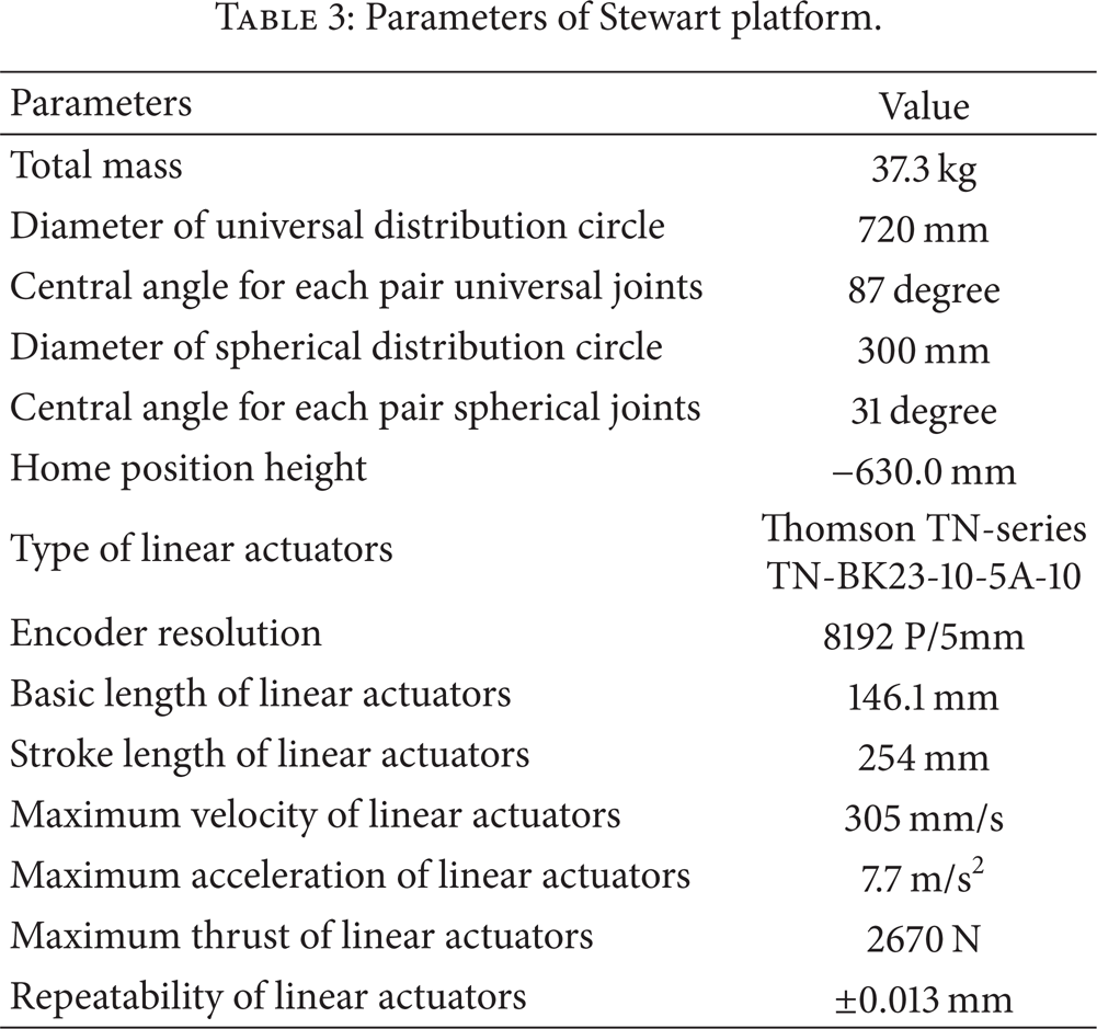
The triple-level spatial positioner for FAST 50 m field model shown in Figure 2 is set up on a scale of 1: 10 of the FAST prototype in Xidian University. The CDPM is driven by six large span steel cable servo systems, with the semispherical cabin as the end effector. The ends of the six cables are connected to the feed cabin with universal joints. As for the driving system of each cable, there are a driving subsystem and two pulleys. The servo drive operates in the position mode and receives modulated pulses from a pulse distribution card developed by the authors. More detailed parameters can be found in Table 1. The AGS is actuated by two reducers and servomotors with brake suits. The parameters of driving system are shown in Table 2. The main parameters of the Stewart platform can be seen in Table 3.
Parameters of CDPM.

Parameters of AGS.

Parameters of Stewart platform.
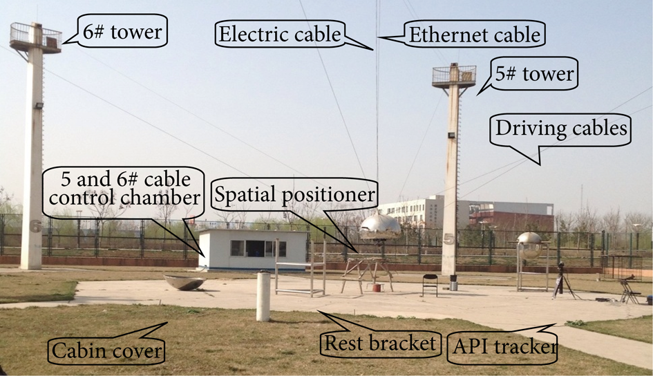
Field photo of the triple-level spatial positioner.
The SynqNet network motion controller is used in the servo control of AGS and Stewart platform, so that the remote control can be realized. The parameters of the motion controller are DSP Analog Devices SHARC 32 bit floating point, speed 40 MHz, user programmable update rate, velocity, acceleration, and jerk 32 bit floating point. The PID filter with velocity and acceleration feedforward compensator is used in each electrical cylinder and servomotor of the AGS and Stewart platform.
In view of the large workspace of this triple-level spatial positioner, an API (Automated Precision Instrument Inc.) Tracker 3–15 laser tracker sensor shown in Figures 2 and 3 is used to accomplish the noncontact laser measurement in calibration and motion control. The main specifications are shown in Table 4.
Specifications of API laser tracker sensor.

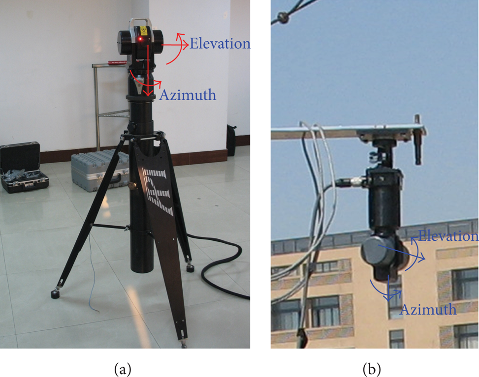
API Tracker 3 laser measurement and 6D-STS.
There are four EVOC industrial computers with Pentium IV-2.4 GHz altogether as shown in Figure 4 in the field model. The computers are connected to a LAN to communicate with each other and to achieve the measuring and control goals.
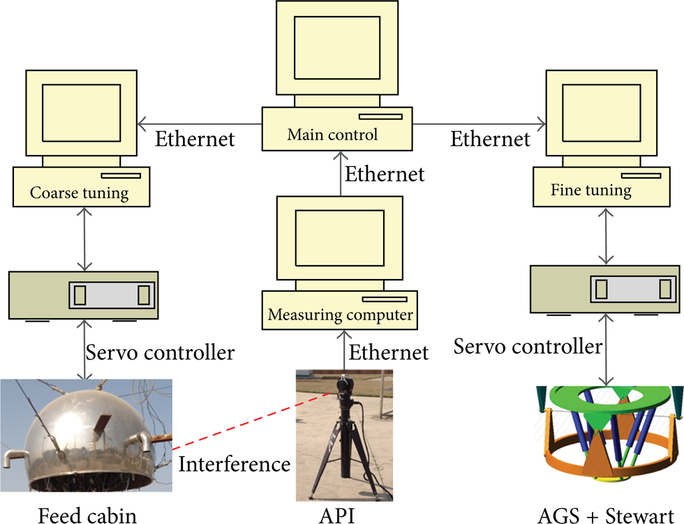
System block of the triple-level positioner.
3. Kinetostatic Calibration of the CDPM
Due to the unidirectional property of the cable, the CDPMs are quite different from those driven by rigid links. CDPMs can be divided into three categories: fully constrained, underconstrained, and point mass CDPMs [9]. In this research, the CDPM uses six cables to control its position and orientation under the effect of gravity; it thus falls into the underconstrained type cables parallel manipulator [9, 10]. One degree-of-freedom out of the six has therefore multiple solutions, which is proved to be the rotation around the vertical axis of the cabin (i.e., yaw motion) [10, 11]. Three angles ψ, φ, and θ under X-Y-Z Euler angles convention are used to describe the orientation of the feed cabin relative to the global frame, in which θ is the angle having multiple solutions due to the underactuation property of this CDPM subsystem.
As shown in Figure 5, once provided the theoretical trajectory of the feed platform for the radio source, the theoretical trajectory for the feed cabin can be determined. So the values of X, Y, Z, ψ, and φ of the feed cabin can be obtained, and the inverse kinematics of the CDPM can be performed if and only if θ is assigned. Thus, evaluating θ of the cabin along its trajectory is the objective of the motion planning for the CDPM. The real-time cable tension optimization procedure is used to solve this problem. The motion of the CDPM is considered as combinations of a series of quasistatic states due to its low velocity, so the force equilibrium equations about the cabin in global frame can be formulated [10, 11]. For simplicity, we take the form as follows, though more detailed expression can be found in [10]:

where J(θ) ∈ R6×6 is a structural matrix,
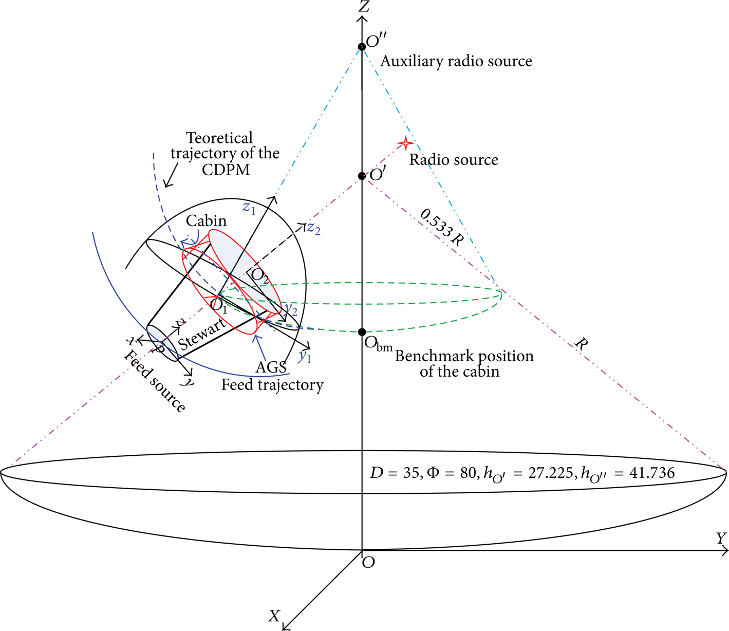
Schematic of the triple-level spatial positioner.
Within an eligible range for each assumed angle θ, the horizontal tension vector H can be evaluated for (1). In order to obtain the most approximately uniform tensions among the six cables, a tension optimization in (2) is performed:
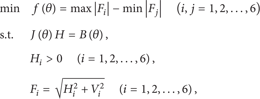
where F i ∈ R2×1 represents the tension vector consisting of horizontal and vertical tension of ith cable and H i and V i indicate the horizontal and vertical component of the cable force in the cable plane. They are determined by the equilibrium equation of ith cable as elaborated in details in [10]. H i >0 shows the unidirectional action force of the cables.
As shown in Figure 5, O
bm
is designed as the ideal benchmark position of the CDPM, together with the orientation angles ψ and φ set to be zeros. And the last orientation angle θ is solved with (2) and are denoted as θ0. For simplicity, the ideal benchmark position and orientation is denoted as

where δ% is percentage of moment output relative to rating moment Mrat = 23.8 Nm, I = 167 is ratio of reducer, and D = 0.384 m and d = 15 mm are radii of bobbin and cable mentioned in last section. Upon finishing the output torque percentage adjustment, the practical benchmark position and orientation X c r of CDPM are measured with the API tracker listed in Table 5.
Benchmark position X c r of CDPM (length unit: m, angle unit: °).

4. Calibration of the Active Gyro Stabilizer (AGS)
The AGS is a two-motor driven orthogonal axes rotation mechanism similar to a gyroscope. Its forward kinematics deals with how to determine the orientation of the end effector given the angular displacement of the two axes. According to the robotic position and orientation transformation rules, the rotation matrix of the end effector relative to the CDPM can be expressed as follows:

where α and β are the yaw and pitch angles, respectively. Then the orientating angle of the feed platform concerning the central axis is γ = arccos(cosαcosβ).
The following inverse kinematics of the AGS is prerequisite for its calibration and control. Given the desired orientation described in global frame

To control and measure the orientation of the AGS, we create marker coordinate A on outer frame (green in Figure 6), marker coordinate B on inner frame (brown in Figure 6) of the AGS with the API laser tracker. Besides, marker coordinate C is established on the cabin (cyan in Figure 6). Thus, this calibration needs measuring the relation between A, B, and C at this very benchmark orientation.

Benchmark orientation of AGS.
Benchmark orientation of the AGS as shown in Figure 6 is generated by driving the two motors to a certain direction until triggering both limit switches of driving system (Figure 7). When this orientation is calibrated, the necessary reversal angles for servomotors to get both inner and outer frames parallel to feed cabin (namely home orientation) can be evaluated. Hereby the home orientation can be achieved by controling the two servomotors with the both angles mentioned above. It is the unique orientation at which the AGS obtains the absolute orientation and make the following motion has definite physical meaning, that is the reason why this very orientation is called benchmark orientation.

Optic switch of the AGS.
The cabin and AGS are located at the rest bracket so that the calibration can be performed. Firstly, the AGS is commanded to rotate both axes with low speed of 1.0°/s to trigger the benchmark limit switch until the motion is terminated by hardware limit function of the servo controllers. At this benchmark orientation, as shown in Figure 6, the orientations of A, B, and C are measured and transformed with API tracker and Spatial Analysis software. Table 6 lists the result.
Benchmark orientation description of AGS.

From Table 6, the angles needed to reset the home orientation from benchmark orientation for AGS can be evaluated by using (5), which are α0 = 30.934° and β0 = 35.436°. After the homing operation, the encoders of AGS will be cleared.
5. Kinematic Calibration of the Stewart platform
5.1. Calibration of the Joints Coordinates
Due to the errors from manufacturing and assembling, the practical configuration parameters of the Stewart platform deviate from the theoretical ones in design drawings. This fact brings about perturbation of the kinematic model, which directly affects the kinematic performance including positioning accuracy. The satisfactory solution to this problem is the parameter calibration described as follows [7]. For the Stewart platform, the configuration parameters to be calibrated with great necessity are the position vectors of universal and spherical joints, that is to say the Cartesian coordinates of the centers of six universal joints in OXYZ and those of six spherical joints in pxyz are as shown in Figure 8.

Schematic of the calibration of universal and spherical joints.
The calibration principle can be explained by taking center of the second universal joint B2 as an example. What we need to obtain exactly is the coordinates of B2 (xd2,yd2,zd2) in OXYZ. Assume the link A1B2 is to be pure stiff; we can measure the coordinate of A1i (x1i,y1i,z1i) in OXYZ, so the following equation holds:

where r is the length of link A1B2, n is the number of candidate orientations of link A1B2 relating to OXYZ during the calibration. In order to reduce the impact of measuring errors on the result of calibration, in general n≥4. For a new orientation of link A1B2, a position measurement of A1 was conducted. The selection of n≥4 yields conflict equations in (6). Thus, the least squared method is employed to solve the equations and derive the coordinates of B2 (xd2,yd2,zd2) in OXYZ. This similar situation was applied to universal joints B i (i = 1,3,4,5,6) and spherical joints P i (i = 1,2,…,6). The coordinates of universal and spherical joints from the calibration are listed in Table 7.
Coordinates of the joints of the Stewart platform.

From Table 7, we can draw the conclusion that there exists considerable error as large as 1.1 mm between the theoretical and practical coordinates of the joints. Meanwhile, these values are embedded in the configuration files of the control software of the Stewart platform.
5.2. Calibration of the Benchmark Position of Stewart Platform
The motion benchmark devices based on optic coupler switch are as shown in Figure 9. The optic coupler switch is mounted on the shaft of spherical joint, and the metal probe designed to provide position signal is fixed on the end of the electrical cylinder. The optic coupler is of low-level trigger type. When the electrical cylinder shortens enough so that the metal probe gets in the narrow slot on the optic coupler, the optical path is blocked and the low-level trigger signal is generated and sent to the servo driver of the motor. The motor driving the electrical cylinder will execute the related actions such as terminating the motion and clear the optical encoder readings. Wherever the mobile platform comes from, the six optic coupler switches of trigger type will determine the only position and orientation of the mobile platform.

Optic coupler limit switch for the Stewart platform.
The process of motion benchmark can be considered as a systemic level calibration of the Stewart platform. The Stewart platform is not able to execute absolute position and orientation until the benchmark calibration course is completed. Note that this very position and orientation are expected to have good repeatability. Moreover, these benchmark devices can also be utilized as limit switches to prevent the cylinder from being damaged.
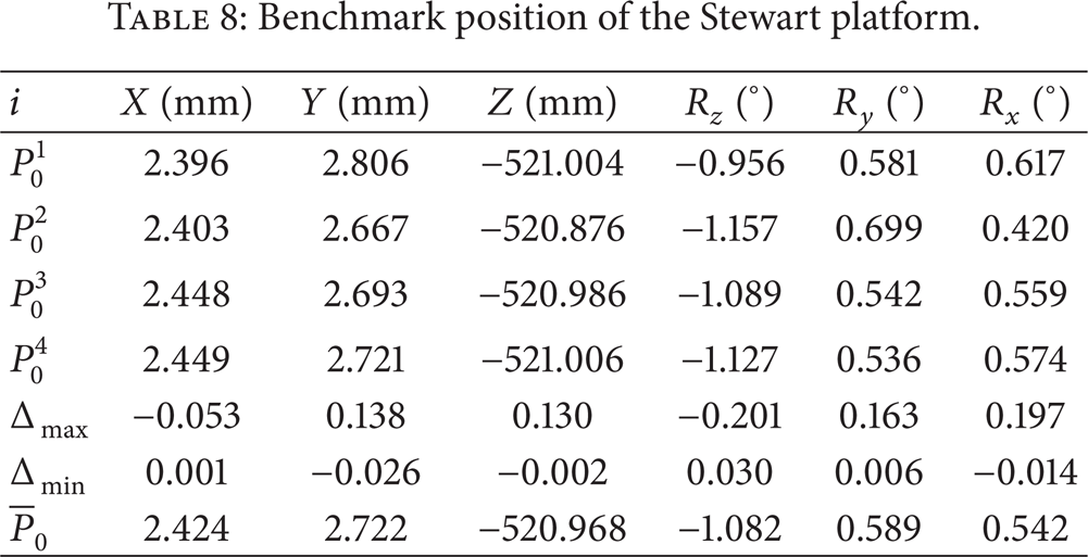
The calibration of the benchmark position can be described as follows. (1) The six cylinders are shortened at the same time via control software. Any a cylinder which is shortened enough to trigger its optic coupler switch will stop moving, but the others go on shortening. Upon all the six cylinders ceasing to move, the benchmark position is generated. (2) Measure the position and orientation with API tracker. (3) Repeat steps (1) and (2) for four times and list the result in Table 8, where, i represents the ith measurement, Δ
max
and Δ
min
represent the maximum and minimum errors in a certain degree-of-freedom among the four groups of data, respectively, and
Benchmark position of the Stewart platform.
6. Experimental Results and Discussions
A series of experiments on the FAST 50 m model have been carried out. The position and orientation of the cabin are directly obtained with the API tracker. AGS is considered as an accurate open-loop servo system. The position and orientation of the feed platform are calculated by the coordinate transformation and the forward position kinematics of the Stewart platform according to the feedback length of the six legs. Two experiments are picked out to validate the calibration and motion control of this CDPM based triple-level spatial positioner.
First experiment deals with the petal trajectory following motion of the feed platform when the cabin is set on the rest bracket. As shown in Figure 10, the theoretical petal trajectory has the base circle with radius of 50 mm and height of −630 mm in local coordinate of the Stewart platform. The amplitude of the petals is 5 mm and 8 periods in total on a whole circle. Figure 11 shows the error details of the petal trajectory tracking. The trapezoidal velocity mode is adopted for the feed platform tracking the radius and the petal, separately in order to make the motion smooth. The positioning error has maximum 6.0 × 10⁻⁴ m, which occurs at the trajectories having the maximum velocity in X and Y directions. The reason for this fact can be that the Stewart platform is designed as position servo system so the static error is proportionally independent of velocity of reference signals. Positioning errors in Z direction are quite small due to the constant input signal in this direction. It is noted that though the servomotors of electrical cylinder are in closed-loop control, the Stewart platform, even the electrical cylinder themselves, is still in open-loop control. In this case, the submillimeter precision of the Stewart platform is satisfactory.
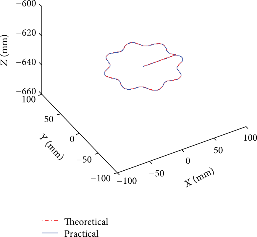
Trajectory tracking of the Stewart platform.
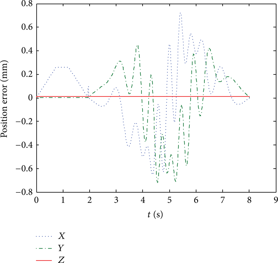
Tracking error of the Stewart platform.
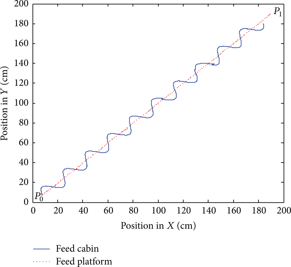
The objective of second experiment is to validate the ability to track a spatial trajectory with existence of external disturbance. In more details, the feed platform is desired to track a spatial line with a length of 255 cm from P0 (7.3, 7.0, 769) cm to P1 (189.5, 189.4, 770.0) cm in first quadrant. The desired linear velocity of both the cabin and platform is 0.5 cm/s. The sinusoidal motion of the cabin with amplitude of 6 cm and frequency of 0.02 Hz is considered as disturbance signal for the feed platform. It is noted that neither the AGS nor Stewart platform has the information of the so-called sinusoidal disturbance. The wind speed is about 1.2 m/s, and the temperature is 28°C. The experimental results of the CDPM based spatial positioner are as follows.
Figure 12 shows the projection of trajectories of the feed cabin and feed platform. We can from the overview shapes conclude that both the feed cabin and feed platform achieve the desired tracking effect. Figure 13 indicates the angles AGS conducted in the tracking experiment. Since the trajectory is planned in a horizontal plane, the pitch angle should be compensated for the Stewart platform is relatively low. Figures 14 and 15 show the root mean squared (RMS) position and pitch angle errors of the feed cabin, which is also the reflection of the poor precision of the large span CDPM. We can find that the positioning and orientating errors do not satisfy the precision demand.
Trajectories of the end effectors.

Driving angles of AGS.

Positioning error of the cabin.

Pitch error of cabin.
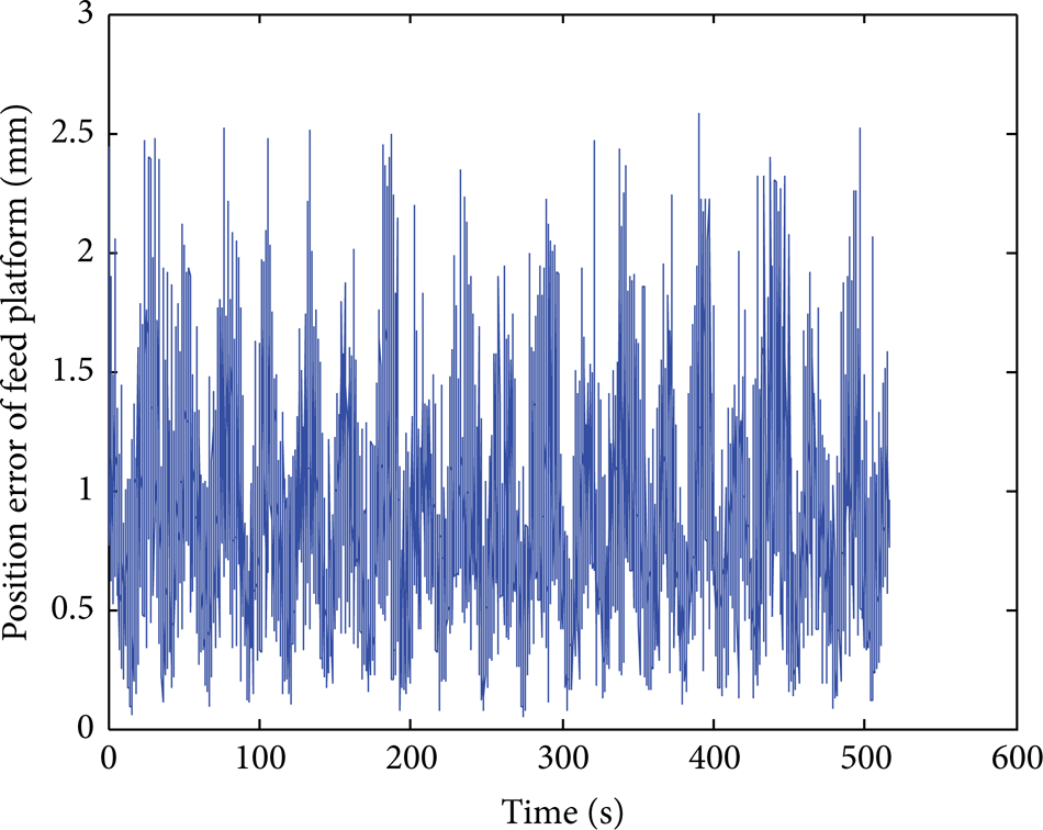
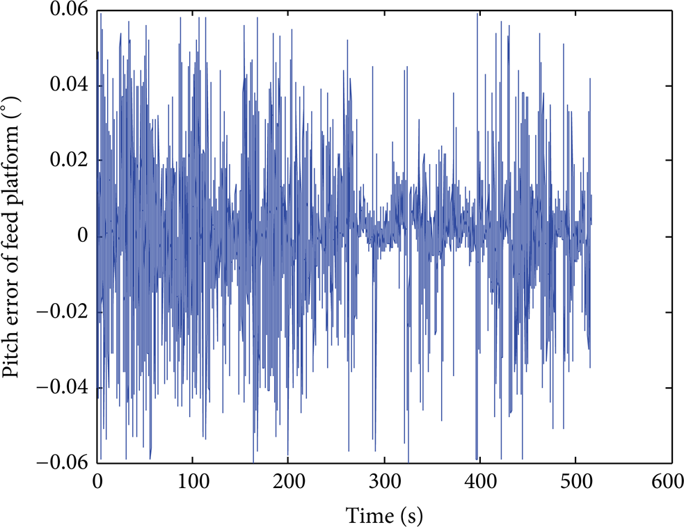
Figures 16 and 17 give the position (RMS) and pitch errors of the Stewart platform. The maximum 2.55 mm position error and 0.06° orientating error validate the favorable precision of this CDPM based spatial positioner. This gives the solid evidence that this triple-level spatial positioner achieves the 4 mm and 8 arc minutes (0.133°) precision, respectively. The Stewart platform and AGS eliminate the position and orientation errors brought in by the feed cabin in collaboration.
Position error of feed platform.
Pitch error of feed platform.
7. Conclusions
This paper elaborates the calibration and motion control design and detailed experiments of a cable-driven triple-level robotic positioner with large workspace. To summarize, the conclusion is that with kinematic calibrations the 50 meter dimensional cable-driven parallel manipulator based triple-level spatial positioner can achieve 2.55 mm RMS positioning and 0.06° orientating accuracy. This is accomplished due to the elimination of millimeter level manufacturing error and submillimeter benchmark evaluation in the calibration process. The calibration strategy becomes straightforward as a result of the sophisticated six-degree-of-freedom API laser measuring equipment in this research. The future work will focus on servo bandwidth and feedback control of the triple-level spatial positioner.
Conflict of Interests
The authors declare that there is no conflict of interests regarding the publication of this paper.
Footnotes
Acknowledgments
This work was supported by the National Natural Science Fund of China, under Grant nos. 51175397 and 51105290, and the Fundamental Research Funds for the Central Universities (JY10000904013). The authors would also like to appreciate the Editor, Associate Editor, and the reviewers for their valuable comments and suggestions.