
Abstract
In order to study the internal flow in centrifugal pump when cavitation occurs, numerical calculation of the unsteady flow field in the WP7 automobile centrifugal pump is conducted based on the Navier-Stokes equations with the RNG k – ε turbulence model and Zwart-Gerber-Belamri cavitation model. The distributions of bubble volume fraction and pressure pulsation laws in the pump are analyzed when cavitation occurs. The conclusions are as follows: the bubble volume fraction is larger on the suction side of impeller blade near the inlet edge, which is consistent with the low-pressure region distribution. Bubble volume is determined by the growth rate and collapse rate of every bubble in the bubble group. The cavitation degree changes over time with the impeller rotation and the bubble growth and collapse coexist in the impeller flow channels. The main pulsation results from the cyclic and static coupling between the impeller and the tongue, while the fluctuating amplitude is increased by the cavitation.
1. Introduction
In the process of the centrifugal pump conveying liquid, high-speed rotating impeller mutually interferes with the stationary volute, which is called “rotor-stator interaction” (RSI). And due to the effect of the fluid viscosity, the flow state inside the pump often presents instability, which causes pressure pulsation in the flow field of the pump. The pressure pulsation can not only produce noise, but also causes the impeller blades alternating load, resulting in blade vibration. Strong pump vibration, abnormal noise, blade fatigue, bearing damage, and other problems can be caused in serious cases [1–3]. Therefore, research on the mechanism of centrifugal pump pressure pulsation, to a certain extent, can reduce the pressure pulsation harm, which has a vital significance in the stable operation of centrifugal pump [4–6]. Many reasons can cause pressure pulsation, but the main reason is generally determined by the inherent characteristics of the fluid machine, resulting in that pressure pulsation can't be eliminated fundamentally. The studies on centrifugal pump pressure pulsation show that swirl, flow separation, turbulence, reflux, cavitation and interaction between pump impeller and tongue, and so forth are likely to cause instability of the fluid flow, resulting in pressure pulsations.
In this paper, numerical calculation of the unsteady flow field in the centrifugal pump was conducted when cavitation occurs, and pressure pulsation at different locations inside the pump was studied. The conclusions are as follows: rotor-stator interaction between impeller and tongue is the main factor generating pressure pulsation, and generation of cavitation will increase pulse amplitude. The paper provides a basic for improving pump structure, reducing vibration noise, and further improving life and using stability of centrifugal pump.
2. Mechanism of Generating Cavitation Pressure Pulsation
From a macroscopic perspective, in the ideal case, when a certain amount of liquid flows through a fixed volume steadily, ignoring other factors, only a small part of the liquid will produce random turbulence and overall flow of liquid will remain basically stable. Reflected in the signal analysis, this means that pressure amplitude will remain stable in the time domain waveform chart. Spectral lines in the spectrums should basically cover the entire frequency range. However, when the fluid contains a large number of bubbles and the generation and collapse of the bubbles do not follow the rules, the fluid phase can be caused to change, which produces pressure pulsation in the flow field. More low frequency components are shown on the spectrogram of the pressure signal.
A large number of bubbles will be produced in the entrance, when the pressure of pump inlet is lower than the saturation pressure of water. In this case, although total volume inside the volute does not change, because of the existence of bubbles, medium density around the cavitation region will reduce accordingly. This causes unequal increase of the absolute velocity distribution when fluid flows from outlet of the impeller. It means that pressure pulsation amplitude at the outlet increases accordingly. On the other hand, the burst of bubble will disturb the low frequency. Pressure pulsation method is to find the corresponding characteristic parameters in advantage of the sensitivity that cavitation changes pressure pulsation amplitude.
3. Numerical Calculation
3.1. Modeling
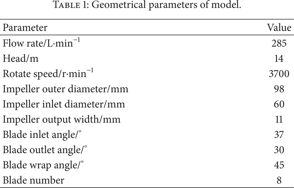
In this paper, a WP7 centrifugal pump, which is produced by a factory in Zhenjiang, is chosen as the model pump. The performance and basic geometrical parameters of the pump are shown in Table 1. The width of the impeller is wider and the impeller is semiopen without front shroud. Section of the suction chamber is annular and section of the volute looks near to rectangle. Three-dimensional model is made by using Pro/E software. The model is shown in Figure 1.
Geometrical parameters of model.

Three-dimension model of centrifugal pump.
3.2. Computational Domain and Meshing
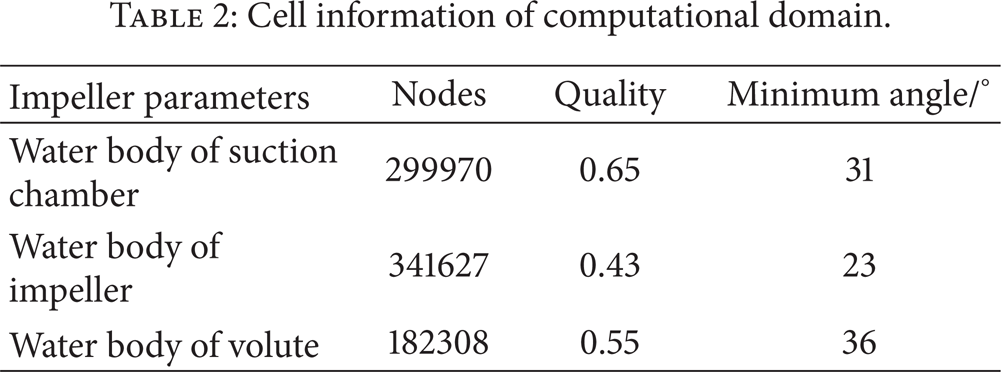
According to the upper and lower cover, impeller, import section, and other components, the water model is made by using Pro/E software, namely computational domain. By means of ICEM software, structure grid of the water body is divided and boundary layer is added on the wall and blade surface. Meanwhile, Y + value is controlled within 100 and computing requirements of RNG k-ω should be met [7–10]. The information of different cell computational domain is shown in Table 2. The final cell computational domain of assembly drawing is shown in Figure 2.
Cell information of computational domain.

Gird assembly drawing of computational domain.
3.3. Basic Control Equation and Boundary Condition
Unsteady numerical calculation can be conducted in the flow field by using CFX fluid computational software, using time-averaged Navier-Stokes as the basic equations, and adopting RNG k-ω turbulence model. Inlet boundary condition is set as pressure inlet and outlet boundary condition is set as mass flow inlet [11–17]. Critical cavitation point is found gradually by adjusting the inlet pressure. In this paper, inlet pressures in design conditions are 101325 Pa, 28725 Pa, and 25325 Pa. Unsteady calculation inside flow field is conducted through three schemes. In terms of this model, the three inlet pressures represent no cavitation, critical cavitation and serious cavitation.
3.4. Cavitation Model
Cavitation model is used to describe the mutual conversion between the gas phase and liquid phase. According to Zwart-Gerber-Belamri cavitation model of CFX software, mass transfer rate of all phase unit volume is
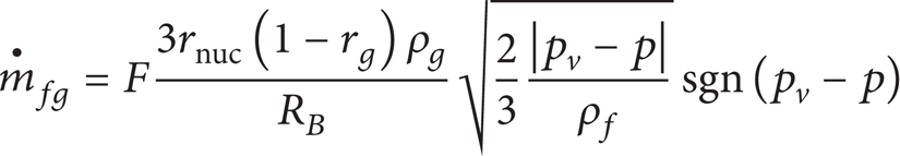
and change rate of vacuolar volume is

In these formulas, F is empirical coefficient; rnuc is initial volume fraction of steam core and the value is 5 × 10⁻⁴; rg is bubble volume fraction and the value is 1 × 10⁻⁶; ρ g is the density of bubble; ρ is the density of water; g is the Gravitational acceleration; R B is bubble radius. pv is vapor pressure. p is fluid pressure around vacuole. V B is bubble volume.
3.5. Selection of Unsteady Time Step and Monitoring Points
A time step is rotating impeller 1° and the value is 0.000045045's. Each cycle time is 0.01621622's. After impeller rotates for two cycles, the flow field presents periodic. Composed of six cycles, the total calculation time is 0.097297297's. In terms of the whole pump, the period of rotation refers to the time required to rotate impeller one cycle. In this paper, T represents the period of rotation and T is 0.01621622's. Although volute is a three-dimensional asymmetric body, impeller blades are axial symmetry. In order to study flow field variation of impeller rotating 360°/N, T1 is represented as the time of an impeller flow channel sweeping over volute tongue. The time is the impeller rotation cycle of 1/N and N represents number of blades, namely T1 = T/N. In the paper, T1 = T/7 = 0.002316602's.
Bubbles are produced in the flow channel and cavitation occurs, when the internal pressure of centrifugal pump reduces to the saturation vapor pressure. The position around the inlet of impeller flow channel is most vulnerable to cavitation, so pressure pulsation should be monitored at different radial conditions of impeller flow channel. As is shown in Figure 3, P1–P4, pressure monitoring points are set up in the middle line of a signal impeller flow channel. Among them, P1 is close to the impeller inlet and P2 is close to the impeller outlet. To monitor pressure pulsation of the coupling in impeller and volute, P5–P10, pressure monitoring points at intervals of 52° are set up in the middle line of volute flow channel. To monitor pressure pulsation of the pump outlet, P11–P14, pressure monitoring points are set up in the diffuser of volute outlet. To monitor pressure pulsation of tongue, P15–P17, pressure monitoring points are set up near volute tongue. All points are in middle section of impeller and volute.
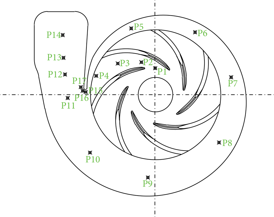
Pressure pulsation monitoring points.
4. Analyses of Calculation Results
4.1. Unsteady Volume Fraction Distribution of Bubbles
Liquid is vaporized and steam is generated, when absolute pressure on the suction side of impeller blade inlet is lower than vapour pressure of the temperature. Along the flow direction of liquid, the pressure inside impeller gradually increases. High pressure liquid causes bubbles to rapidly shrink and rupture, when the pressure is up to a certain value. The surrounding liquid fills cavity at a high speed and forms the impact. The process of centrifugal pump cavitation is shown as above. Since cavitation is an unsteady process of bubbles formation and collapse, unsteady volume fraction distribution of bubbles is studied under the cavitation condition.
As is shown in Figure 4, it represents volume fraction distribution of bubbles and static pressure distribution; when inlet absolute pressure is 25325 Pa serious cavitation occurs under the pressure in the pump. As is shown in Figure 4(a), the results of unsteady calculations show that cavitation occurs mainly on suction surface of blades. More serious cavitation occurs on the suction surface near the inlet, and the position is relatively identical with the region below 10735 Pa in the static pressure distribution. The reason cavitation does not obviously occur in the tongue and inlet is that the pressure of volute and inlet is much higher than vapour pressure.

Middle cross section of model pump when absolute pressure is 25325 Pa.
To analyze cavitation of impeller flow channel, the state is studied when inlet absolute pressure is 25325 Pa and serious cavitation occurs. Figure 5 shows bubble volume fraction distribution of a single blade suction surface at seven different moments when the impeller rotates a cycle. From the figure, changes with time can be seen in the cavitation area of blade suction surface. Meanwhile, unsteady process of cavitation can be seen from strong to weak and then from weak to strong. Observing calculation results under different time, the strength and regional location of cavitation on a single blade suction surface are different to some extent; nevertheless, the most serious cavitation of blade suction surface occurs in latter position of inlet, and cavitation is not obviously produced around blade inlet. Bubble volume is determined by the growth rate and collapse rate of every single bubble in bubble group. The figure shows that cavitation region is composed of bubble group. Pressure of blade suction surface varies with rotation of impeller. Continuous process of bubble growth and collapse exists in impeller runner at the same time. Cavitation degree varies with the time.

Bubble volume fraction distribution of a single blade suction surface at the same time.
As is shown in Figure 5, bubble volume fraction of blade suction surface in impeller flow channel is largest at the time T1, and area is largest when volume fraction is up to 0.8. Bubble volume fraction of blade suction surface in impeller flow channel is least at the time T5 and maximum value is below 0.8. From the time T1 to T5, bubble volume fraction of blade suction surface is reducing. This is because growth rate of every single bubble in bubble group is less than collapse rate during the process, which indicates pressure of blade suction surface is at an increasing stage. Volume fraction is largest at the time T5. Growth rate is approximately equal to the collapse rate and the pressure reaches the maximum value. From the time T5 to T7, volume fraction of suction surface is an increasing process. Growth rate of every single bubble in bubble group is higher than collapse rate during the process and pressure of blade suction surface is at a reducing stage.
4.2. Analysis of Pressure Pulsation in Cavitation State
Working conditions are selected when inlet total pressures are 101325 Pa, 28725 Pa, and 25325 Pa, while unsteady calculation of inner flow field is conducted under three conditions. In this model, three inlet pressures, respectively, represent noncavitation, critical cavitation, and severe cavitation.
The effect of pressure pulsation on cavitation is analyzed as shown in Figure 6. From Figure 6, pressure pulsation frequency diagram is drawn by monitoring points P5–P8 inside volute flow channel under different inlet pressure. Each monitoring point is mainly affected by low frequency, and low frequency region is chosen to be analyzed. In the same cavitation condition, from monitoring point near tongue P5 to P8, dominant frequency is blade frequency and main frequency value is gradually decreasing. At the monitoring point P8, main frequency reaches the minimum and pressure pulsation generated in the tongue decreases with rotation of impeller. The law is followed in the three cavitation conditions, which illustrates pressure pulsation is mainly derived from coupled area between impeller and tongue in noncavitation, critical cavitation, and severe cavitation condition. Pressure pulsation frequency diagram in different cavitation conditions is shown in Figure 6. As a result of cavitation, pressure pulsation amplitude of monitoring points P5–P8 is increases significantly, especially main frequency. As is shown in Figure 7, main frequency of monitoring point P5 in critical cavitation condition is about 2.7 times higher than that in noncavitation condition, and main frequency in severe cavitation condition is 3 times higher than that in noncavitation condition. At the same time, cavitation not only enhances the strength of discrete pulsation but also enhances the strength of broadband pulsation, which produces many low frequency contents. In the volute flow channel, pressure pulsation amplitude increases with the degree of cavitation; meanwhile, discrete pulsation and broadband pulsation also increase.

Pressure pulsation frequency in three cavitation conditions.

Main frequency of monitoring points in three cavitation conditions.
Pressure pulsation frequency diagram and main frequency amplitude comparison diagram monitoring points P15–P17 around the volute tongue under different inlet pressure are shown in Figure 8. In the diagram, main frequency amplitude is the same as the blade frequency, which illustrates that the main origin of pressure pulsation comes from coupled area between impeller and volute tongue. As a result of cavitation, pressure pulsation amplitude of monitoring points P15–P17 increases obviously, of which main frequency changes most. Main frequency of monitoring point P15 in critical cavitation condition is 1.22 times higher than that in noncavitation condition, and main frequency in severe cavitation is 2.4 times higher than that in noncavitation condition. Growth rate of amplitude of the rest points is close to that of point P15. Meanwhile, the intensity of broadband pulsation increases with the degree of cavitation.

Pressure pulsation frequency and main frequency amplitude comparison diagram in three cavitation conditions.
5. Experimental Results and Analysis
Product is processed and sent to the laboratory for external characteristic test. As is shown in Figure 9, head and efficiency of pump measured in experiment are compared with numerical results, which illustrates that calculating value of head and efficiency is higher than experimental value. There are three main reasons that produce deviation. First, in order to make model and calculation, the model is simplified to some extent in the process of simulation, ignoring volume loss of pump. Second, unit efficiency of pump system is measured in the experiment, while simulation only aims at pump efficiency, ignoring various losses in the pipeline. Third, due to the limitations of casting process, model of calculation has some deviation to real model. Overall, variation trend of calculation value is close to experimental value, and numerical calculation is credible.

Comparison between calculating value and experimental value.
6. Conclusions
Cavitation occurs mainly on suction surface of blades and more serious cavitation occurs on the suction surface near the inlet. With the impeller's rotation, the cavitation degree changes over time and the growth and collapse of bubbles coexist in the impeller flow channel. The process of increasing (decreasing) bubble volume of blade suction surface is also the process that growth rate of each bubble in bubble group is higher (lower) than collapse rate.
In noncavitation, critical cavitation, and severe cavitation conditions, blade frequency is still the major ingredient of pressure pulsation. The main pulsation results from the cyclic and static coupling between the impeller and the tongue. Frequency domain characteristics of monitoring points keep pace with that of design condition.
Pressure pulsation amplitude is sensitive to the changes of cavitation. Discrete pulsation and broadband pulsation in the volute increase significantly with the degree of cavitation.
Conflict of Interests
The authors declare that there is no conflict of interests regarding the publication of this paper.
Footnotes
Acknowledgments
This research was supported by the Priority Academic Program Development of Jiangsu Higher Education Institutions, the National Natural Science Foundation of China (Grant no. 51279069), the National Natural Science Foundation of Jiangsu Province (Grant no. BK20131256), the Graduate Innovation Project of Jiangsu Province (CXLX12_0642), the National Science and Technology Support Project (2011BAF14B01), and Science and Technology Support Project of Jiangsu Province (BE2012150).