
Abstract
It is known that force exchanges between a robotic assistive device and the end-user have a direct impact on the quality and performance of a particular movement task. This knowledge finds a special reflective importance in prosthetic industry due to the close human-robot collaboration. Although lower-extremity prostheses are currently better able to provide assistance as their upper-extremity counterparts, specific locomotion problems still remain. In a framework of this contribution the authors introduce the multibody dynamic modelling approach of the transtibial prosthesis wearing on a human body model. The obtained results are based on multibody dynamic simulations against the real experimental data using AMP-Foot 2.0, an energy efficient powered transtibial prosthesis for actively assisted walking of amputees.
1. Introduction
A definition of the functionalities/duties between a human and a robotic device, also the organization of their interaction, basically, includes a number of different criteria that influence the effectiveness of the “human-robot” system. The hierarchy of criteria importance depends on a general approach in a certain domain application. Generally, the requirements in a robotic device design should assure the maximum economical effectiveness of the system in combination with a personal security of the end-user.
Robots for physical assistance to humans are meant to reduce fatigue and stress, increase human capabilities in terms of force, speed, and precision, and improve in general the quality of life. In other words, the crucial goal of a robot for physical human-robot interactions (pHRI) is a generation of supplementary forces to overcome human physical limits. Moreover, the human can bring experience, global knowledge, and understanding for a correct execution of movements [1]. In case of assistive devices, an improved analysis of the problems related to the physical interaction with robots becomes mandatory. Also, in a special perspective for the interaction with humans should be considered the design of the mechanism, sensors selection, actuators, and control architecture [2].
Compared with healthy persons, walking amputees require 10–60% more metabolic energy depending on walking speed, physical individual properties, cause of amputation, amputation level, and prosthetic intervention characteristics. Furthermore, amputees walk at 11–40% slower self-selected gait speed than do persons with intact limbs [3, 4]. To date, commercially available prostheses comprise spring structures that store and release elastic energy throughout each walking stance period [5]. Due to their passive nature, such prostheses are unable to generate more mechanical energy than what is stored during each walking step. Also, experiences in clinical environment indicate that transtibial (TT) amputees suffer from a nonsymmetrical gait while wearing a completely passive prosthesis [6]. In distinction, the human ankle performs positive net work and has a greater peak power over the stance period, especially at moderate to fast walking speeds [7, 8].
In literature several engineering challenges still slowing down the further development of a powered ankle-foot prosthesis [9, 10] are discussed. In the field of prosthetic leg design, a critical objective is to progress a powered ankle prosthesis capable of mimicking the dynamics of the human ankle. A study of TT prosthetics research contributions shows that none of the commercially available devices are skillful of mimicking an human ankle-foot complex. With current actuator technology, it is challenging to build an ankle-foot prosthesis that matches the size and weight of the human ankle-foot structure but still provides sufficient stance-period work and instantaneous power output to drive an amputee. In 1998, Klute and colleagues [11] were the first to build a powered ankle-foot prosthesis efficient in performing net positive work. Their device employed a pneumatic actuation strategy with an off-board power supply. More recent work has focused on the design of energetically autonomous powered systems [12–14]. In the growing field of rehabilitation robotics, the use of compliant actuators is becoming a standard where accurate trajectory tracking is not required. The advantages of such actuators are represented by safely interaction with the patient and large forces absorption during gait. In the particular case of trans-tibial prostheses, compliance of the actuation provides even more advantages. Besides shock absorption in case of collision with objects during walking, energy provided by the actuator (e.g., electric motor) can be stored into its elastic element (e.g., spring in series). The current state-of-the-art in powered ankle-foot prostheses with focus on devices using compliant actuators has been presented in [15].
In the next sections, the authors are focused on the influences on normal human gait of the forces that are generated by a motor and forces that are stored in and then released by springs, also the reaction of the mechanism as a whole in interaction with user. Then, the comparison between the real “human-robot” setup and virtual model is discussed.
2. The Ankle Mimicking Prosthetic- (AMP-) Foot 2.0: Background
This section is dedicated to a summary description of the prosthesis used in the study. The section includes presentation of the AMP-Foot 2.0 mechanical design and validation part in the framework of real experiments, with an amputee subject participation.
2.1. Design of the AMP-Foot 2.0
The AMP-Foot 2.0, see Figure 1, claims a new energy concept, based on a principle of optimal power distribution which is elaborated in [16]. Basically, the working principle is similar to existing powered assistive devices, except that the actuator is working during the complete stance phase. Gravitational potential energy is gradually stored into a series elastic element, in time which the drive still has to provide the same torque and power output. But there is approximately 3 times more time available to generate the power by the electric motor. As a consequence, the overall power rating of the actuator can be divided by approximately the same amount, reducing the weight and size of the drive power considerably.
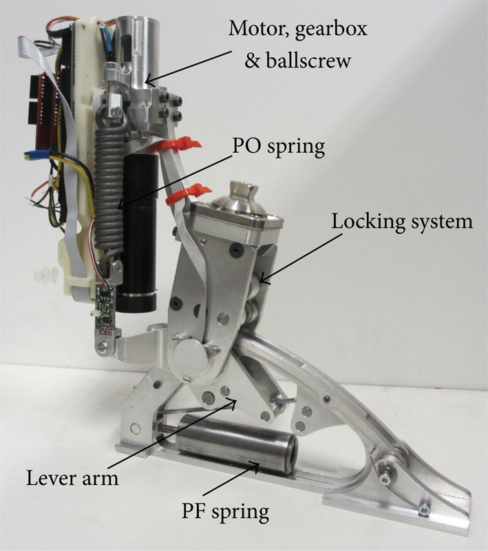
Design representation of AMP-Foot 2.0.
The functional principle of the AMP-Foot 2.0 uses a “plantar flexion (PF)” spring, which stores energy from the controlled dorsiflexion phase of stance. An electric actuator is loading a “push-off (PO)” spring during the complete stance phase. The prosthesis includes a locking mechanism which provides the energy implementation into the PO spring and can be delayed and released at push-off. This way, full torque and power required for locomotion can be obtained with less power from the actuator.
Structurally, the device consists of three bodies: a leg, a foot, and a lever arm, pivoting around the ankle axis; see Figure 2. As mentioned before, the system comprises 2 spring sets: a PF and a PO spring set. The PF spring is placed between a fixed point p on the foot and a cable that runs over a pulley a to the lever arm at point b and is attached to the lever arm at point c, while the PO spring is placed between the motor-ballscrew assembly and a fixed point d on the lever arm. A critical part of this device is the locking mechanism, that is meant to bear high forces while being as compact and lightweight as possible and is represented by a four bar linkage moving in and out of its singular position. The working principle of such a system has been proposed in [17].
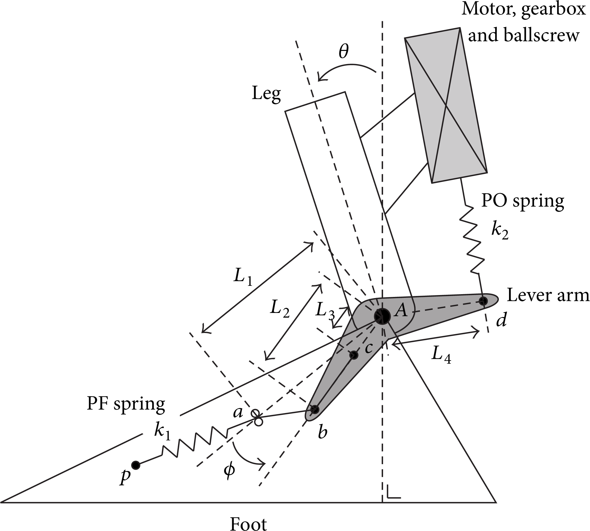
Schematic representation of AMP-Foot 2.0.
The locking mechanism which provides a rigid connection between the leg and the lever arm when energy is injected into the system is not represented in Figure 2.
In order to illustrate the behaviour of the AMP-Foot 2.0 prosthesis, the gait cycle is divided in 5 phases starting with a controlled plantar flexion from heel strike (HS) to foot flat (FF); see Figure 3. A step is initiated by touching the ground with the heel. During this phase the foot rotates with respect to the leg, until θ (= ϕ) reaches approximately −5°. This is followed by a controlled dorsiflexion phase ending in push-off at heel off (HO), during which a generation of propulsive forces by Soleus and Gastrocnemius muscle groups will have place. In the late stance phase, the torque produced by the ankle decreases until the leg enters the swing phase at toe off (TO). Once the leg is engaged in the swing phase, the foot resets the locking mechanism.

Working principle of AMP-Foot 2.0 during a complete gait cycle.
The more detailed description of AMP-Foot 2.0 dynamic behaviour during a complete gait cycle can be found under contribution [16].
2.2. Validation of the AMP-Foot 2.0 Device
The experiments with participation of one disabled patient were effectuated by the research group of Vrije Universiteit Brussel [18] and, in present paper, the authors are referring to results obtained from those experiments. Briefly, in the performed experiments one transfemoral amputee subject of 75 kg was considered and the experiment was divided in three trials: (1) walking at a self-selected speed on a treadmill; (2) walking speed raised to a faster cadence; (3) an overground walking at self-selected speed; see Figure 4 [19].

Overground walking at self-selected speed (∼2.9 km/h).
Conform analysed data acquired during the experiments, and compared to existing powered prosthetic devices, it was observed that the AMP-Foot 2.0 prosthesis can improve an amputee gait, in conditions when little power is required for the actuation. Since the present contribution is focused on modelling and simulation approach of human-robot system, all additional details regarding the real experiment design, prosthesis behaviour, power consumption, and torque characteristics are given in [18].
3. Modelling and Simulations in Virtual Environment
In this section, the authors present modelling methods of the AMP-Foot 2.0 device. Then, modelling and simulation results of an amputee walking using the assistive device are described. Further, the comparison of a normal walking (healthy person) and the same person wearing the AMP-Foot 2.0 is effectuated. The section is concluded with discussion on obtained results from simulations and the real experiments, referred in Section 2.2.
Computational dynamics has grown in last year's along the need to develop simulations and analysis for mechanical systems that consist of interconnected bodies. Simulation is meant to describe and analyze the behaviour of various system configurations, ask what-if questions about the real system, and optimize the structural design.
Due to the high complexity of modern robotic systems, almost any research conducted in the area of robotics can benefit from a simulation of the system behaviour before experiments on a real platform take place [20]. The computational modelling including anatomic, physiologic, and engineering analyses serve to study various activities in a normal and pathological condition of humans. Computer simulations represent an effective, faster, and cheapest approach than experiments, which necessarily consume physical resources. Computer modelling is considered the most effective, when employed in combination with real experiments.
3.1. Modelling Approach for AMP-Foot 2.0
A 3D model was developed in conformity with the real mechanical properties of AMP-Foot 2.0 device. In other words, all material and structural characteristics are preserved relative to the existing prototype. In order to model and simulate the AMP-Foot 2.0 prosthesis, MSC Adams 3D multibody dynamics software was used [21]. The geometries of the AMP-Foot 2.0 component parts were exported from Autodesk Inventor software in MSC Adams environment and were converted into a set of Adams/View geometry elements. This importing approach reduces the need to recreate geometry primitives within Adams software and enhances the ability to realistically view the behavior of complicated mechanical systems. After importing, the co-rrelated constraints between all geometry parts were defined and applied to the model. Two spring sets (PF and PO), which play a critical role in AMP-Foot 2.0 dynamic behaviour, have been modelled according to the real design stiffness and damping characteristics. The stiffness of the PF spring is about 300 N/mm and for every PO spring the value of stiffness is modeled as 60 N/mm. Damping values were determined experimentally, and were found to be 10 Ns/mm for PF spring set and 1.2 Ns/mm for each PO spring respectively. The FF phase is considered as the initial position of the model. In the beginning stage of this study the model dynamic behaviour, see Figure 5, was analysed without human body model and was elaborated in [22]. The AMP-Foot 2.0 model complexity can be appreciated and visualised in Figure 5, where moving parts and constraints of the model are presented. There are 11 degrees of freedom (DoF) in the AMP-Foot 2.0 system.

The AMP-Foot 2.0 model composition and DoF.
The model includes 2 actuation forces: one represents the motor actuator, which is constantly pulling up the PO springs from HS to TO period of the gait cycle; the second force is responsible for triggering the locking mechanism. The control of the force actuation period is based on timing approach, implemented in the model in form of a STEP function.
The STEP function approximates the Heaviside step function with a cubic polynomial and has the following format: STEP (x,x0,h0,x1,h1). It has continuous first derivatives. Its second derivatives are discontinuous at x = x0 and x = x1, where x is the independent variable (time, in present model), x0 is a real variable that specifies the x value at which the STEP function begins, x1 is a real variable that specifies the x value at which the STEP function ends, h0 is the initial value of the step, and x1 is the final value of the step.
The arrows, that can be observed in Figure 6, are representing the actuation and tension forces during the simulation.
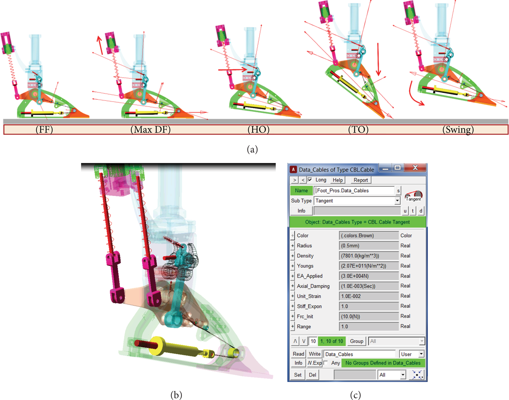
(a, b) Simulation of AMP-Foot 2.0 behaviour. (c) Cable properties GUI.
Due to cables nonlinear geometric properties and a complex static and dynamic behaviour, the challenge was to model the cable segments which play an important role in a force transmission system of the AMP-Foot 2.0. The cable transmission system was modelled using TKC toolbox feature and the tension forces inside of the system were obtained [22].
The cable properties, such as density, Young's modulus, axial stiffness, and strain value, are defined with respect to the ones used in real mechanical system and were determined experimentally. These properties are presented in Figure 6(c) and can be easily modified for further experimental purposes within the framework of Graphical User Interface (GUI), developed in MSC Adams software; see Figure 6(c); the mass of the cable elements is assumed to be negligible.
3.2. Modelling and Simulation of Human Walking during Wearing the AMP-Foot 2.0 Prosthesis
There are specialized commercially available simulation tools that can be used for analysis of human walking, such as AnyBody [23], OpenSim [24], SIMM [25], and LifeMod [26]. However, these tools cannot be used for analyzing human-robot interactions, which is becoming an essential requirement for modeling and simulation of robotic systems as their physical interaction with humans becomes more complex. In general, the modeling and simulation phase of the development of such systems is becoming demanding. Since the robot and robot-human interactions increase in complexity, the simulation with a single simulation tool is not effective anymore. Therefore, in this research work the combination of MSC Adams with LifeMode plug-in was used as the most appropriate.
3.2.1. Methods
The creation of human models begins by generating a base human segment set, followed by joints, soft tissues, and contact elements between the model and the environment. In order to study the influences of AMP-Foot 2.0 device on normal overground walking the mechanical model of the human body was built using the Lifemodeler plug-in in framework of MSC Adams environment. This combination of tools supports the analysis of the “human-robot system” effectiveness and mutual interaction. The considered model, see Figure 8, includes a model of human's lower body (two legs and pelvis) which is rigidly attached to the right extremity AMP-Foot 2.0 prosthesis. Once the segments of the lower body are established, joints are created between the segments. Along an inverse-dynamics simulation, joints learn angulation patterns while the model is being driven by the motion capture data. The nominal joints stiffness for both legs at the hip, knee, and the ankle is assumed to be 1e5 Ns/mm and the damping to be 1e4 Ns/mm. The joint consists of a triaxis hinge and passive or active forces acting on each of the three degrees of freedom. They are implemented as an assembly of two “virtual” bodies of negligible mass and inertia and three revolute joints; see Figure 7. For every joint there are three axes: sagittal, transverse, and frontal. The Lifemode software offers the possibility to define every axis in a way suitable to certain application. The axes of lower limb joints in present human model are defined as in the table in Figure 7.
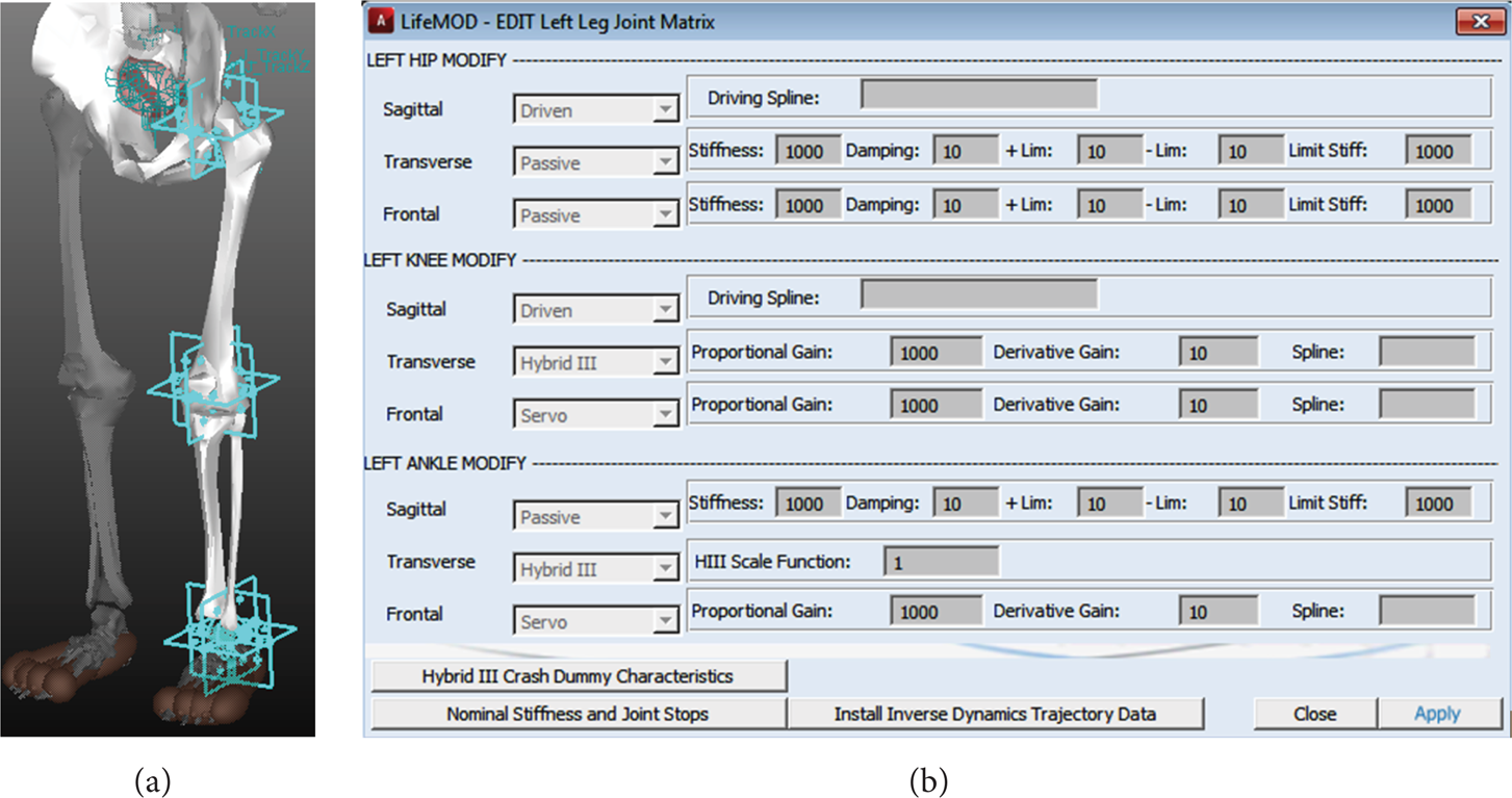
Joints representation and definition.
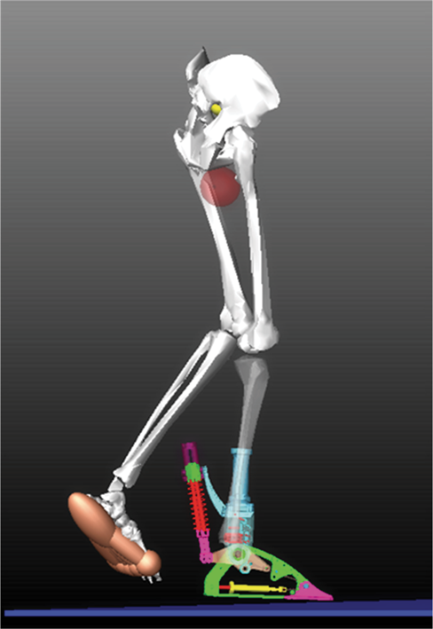
Model of human lower limbs cosimulated with AMP-Foot 2.0.
The settings specified for every joint axis in the model are interpreted as follows.
Driven. Kinematically driven using data from a driving spline.
Passive. A torsional spring force with user-specified stiffness, damping, angular limits, and limit stiffness values. These joints are used in an inverse dynamics analysis to record the joint angulations while the model is being manipulated with motion agents.
Hybrid III. The Hybrid III strength model is created for the individual joint axis with a user-specified scale value. The Hybrid III strength model is based on physical measurements of an actual crash dummy. The strength model consists of nonlinear stiffness, damping, and frictional values and also includes joint limit stop stiffness with hysteresis.
Servo. This selection creates a trained PD-servo type controller on the joint axis. The joint is commanded to track an angular history spline with a user-specified gain on the error between the actual angle and the commanded error. A user-specified derivative gain is specified to control the derivative of the error.
It is important to notice that the mass (75 kg) of the whole human body is considered in simulation, although just the lower part is represented. The human body model generated by the LifeMod plug-in stores the joint motion trajectories in MSC Adams. These trajectories are used during simulation as reference inputs for the joints’ PD controllers which are also implemented in MSC Adams.
For simulation, driving of the human body is based on captured motion data obtained through marker-based motion capture system. Motion capture (MOCAP) systems track the trajectories of markers attached at various locations on the body. The marker trajectories are then used to train the human model. During the training, the response of the body is recorded and later used for a forward dynamics simulation. Marker trajectory data is used to drive elements called “motion agents,” which are massless parts fixed to the body segments using spring elements.
The right foot part was removed and replaced by the AMP-Foot 2.0 model and connected to the right lower leg by a fixed joint; see Figure 8. Then, contact forces between prosthesis toe, heel parts, and the ground were defined as an IMPACT function model. The IMPACT function represents a simple model for contacts. It evaluates a force that turns on when a distance falls below a nominal free length (when two parts collide). The force has two components: a spring or stiffness component and a damping or viscous component. The stiffness component opposes the penetration. The damping component of the force is a function of the speed of penetration and opposes the direction of relative motion.
3.2.2. Results
The obtained simulation data were filtered by low pass filter and processed accordingly. In Figure 9 the ankle angle data of the human body model with the same physical properties as in real experiment are illustrated (weight 75 kg, height 175 cm, male) during normal over-ground walking. In the first simulation the human was walking without AMP-Foot 2.0 prosthesis, using a normal human foot model (see Figure 9, blue dot-line).

Ankle angle during normal walking of the same subject: red graph with AMP-Foot 2.0; blue line using the healthy foot.
Afterwards, the normal foot was removed and replaced by the AMP-Foot 2.0 model and, therefore, we can follow from the graph (see red line representation) the consequences for this change in gait kinematics. Please notice that in the first slot of time the AMP-Foot 2.0 prosthesis is passive; there is no force acting on the motor part and pulling the spring sets. The single actuation is coming from the human leg during walking only. In the grey zone, see Figure 9, the AMP-Foot 2.0 becomes actuated and, as a result, we can observe an increase of the ankle angle, due to the provided push off propulsion force of the prosthetic device.
In Figure 10 are illustrated the obtained torque values of the right lower limb with the AMP-Foot 2.0 prosthesis attached.
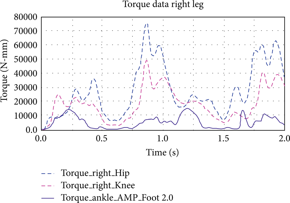
Torque values for right limb.
Also, a slight difference was observed at the knee level joint. In case the AMP-Foot 2.0 is attached to the human leg model, the authors noticed a small knee angle increase; see Figure 11. This occurrence can be explained by the lower compliancy in the TO moment. Then the locking mechanism opens, providing the additional propulsion force to the leg.
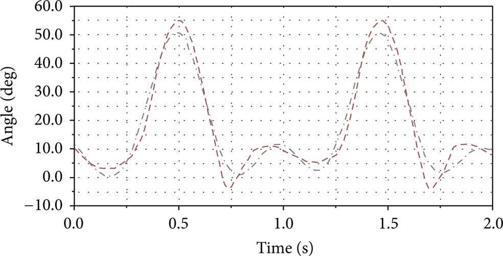
Knee angle: red line, with AMP-Foot 2.0 model; grey line, with human foot model.
As was discussed before, the authors were interested to make a comparison between data from simulations with the data, based on real experiments; see Figure 12.

Ankle angle comparison: red line: simulation of human model during wearing the AMP-Foot 2.0; blue line: simulation of human model without AMP-Foot 2.0; green line: real experiment data of subject during wearing the AMP-Foot 2.0 device.
Conform Figure 12, the time-based data on level ground walking, one can observe the similarities between the angle ankle data of the human model wearing the AMP-Foot 2.0 device and the walking pattern of real amputee subject with attached prosthesis. It can be noticed for the human model with the AMP-Foot 2.0 that there is an increase of the ankle angle around HO moment. This fact can be the result of the influence of contact forces between the heel and the ground part. In other words, when the heel is touching the ground the reaction forces are pushing up the AMP-Foot 2.0 prosthesis, by this way creating an additional torque motion.
4. Discussion
It is crucial for design and control developing of assistive devices to have a model of the robotic system interacting with the human before the actual physical system is ready for the use. Sometimes, performing the real experiments is too exhausting, expensive, or almost impossible and in this case modeling and simulation approach is considered very effective. In the framework of this paper the authors have researched in virtual environment the differences between human walking during wearing an assistive device and normal walking of the healthy person. In both simulation and real-life testing the same human model was considered. This experiment is impossible to be repeated in real life. It was expected to have some differences in the ankle angle data, but the main conclusion is that the human walking is not affected in negative way while wearing the AMP-Foot 2.0. The powered device is providing the human leg with additional propulsion force that helps locomotion.
If we will refer to real experiments, performed with an amputee person with comparison to results obtained from simulations with human model during wearing the AMP-Foot 2.0, we can notice many common similarities in walking pattern. Even, if the gait kinematics of people is individual, (in simulations a similar subject with the same physical characteristics was considered) the obtained results remain valid and can be interpreted. If one will do the comparison between the normal walking simulation and both experiments which uses the AMP-Foot 2.0 prosthesis (Figure 12), one will observe some difference in TO moment. In case of normal walking without the device the transaction of the foot from TO to a swing moment is more compliant. In case of simulations there can be other external factors that can slightly influence obtained data results, such as the simplified contact definition (which is not so complex as in case of real foot-ground contact).
5. Conclusions
The main focus in the framework of the presented study was to inspect how the attached trans-tibial prosthesis will influence normal healthy human walking kinematics and how close the AMP-Foot 2.0 working behaviour comes to a real human foot subsystem. The effectiveness of human-robot interaction was analyzed during the tests with a real subject and in virtual environment. The authors admit that it is difficult to compare individuals having a different walking pattern, even if for simulation a subject with the same physical parameters as the one tested in real experiment was considered. Moreover, the simulation comparison (subject walking with and without AMP-Foot 2.0) is almost impossible to arrange in real life. This fact that the simulation results more interesting and significant.
Thanks to the built human-prosthesis model further improvements on prototype design parameters can be achieved and the prototype can be adapted to certain subject's individual properties. The result data demonstrate that AMP-Foot 2.0 prosthesis can successfully replace the human ankle-foot subsystem, provided some individual adjustments are made.
Conflict of Interests
The authors, Grosu Svetlana, Pierre Cherelle, Chris Verheul, Bram Vanderborght, and Dirk Lefeber, declare that there is no conflict of interests regarding the publication of this paper.
Footnotes
Acknowledgments
This work has been partially supported by the European Commission 7th Framework Program as part of the CORBYS (Cognitive Control Framework for Robotic Systems) project under Grant Agreement no. FP7 ICT-270219.