
Abstract
The goal of this study was to develop a novel approach to the study and design of metamorphic mechanisms, based on a consideration of gene structure, mitosis, and cell fusion. In this study, we treat kinematic pairs as basic connection units that function similarly to the base pairs in DNA molecules and present expressions for the configuration of each kinematic pair in a mechanism. We also develop some methods to describe changes in the number of links, number of kinematic pairs, and pair features (type and configuration) during the folding process. Finally, we propose a method based on mitosis and cell fusion for studying the folding process and innovating mechanism design. In this method, a mechanism is first decomposed into some basic kinematic chains, and then these chains (with folding function) are fused into one complete mechanism. Two examples are presented to demonstrate the use of the methods proposed in this study. Overall, we found that, for innovation in mechanism design, it is useful to consider gene connection and mutation as well as mitosis and cell fusion.
1. Introduction
In daily life, everybody is very familiar with folding mechanisms which has brought great convenience for us. However, many folding mechanisms can be grouped into the category of metamorphic mechanisms. The concept of metamorphic mechanism was firstly proposed by Dai and Rees Jones in 1999 [1]; since then this research field has received extensive attention of scholars at home and abroad. Dai systematically expounds several important issues in literature [2], and the authors in literature [3] give the definition, essence, and characteristics for metamorphic mechanisms from different perspectives. The essence of metamorphic mechanisms is that the topological structure is changed in the process of mechanism motion, and a number of researchers have contributed much for describing the topological change of the metamorphic mechanisms [4–7].
Earth has evolved for about 3.5 billion years, with the animals and plants in nature providing continuous inspiration for human innovation and design. For instance, the airplane and submarine were created based on inspiration from birds and fish, respectively, and have had a significant effect on human life. Vincent [8] points out that many creatures in nature now exist in the folded deployable (metamorphic) form, such as birds’ wings. Based on these facts, many researchers began to focus on the design of folded deployable (metamorphic) structures based on bionic principles, to improve the performance of such existing structures, or to propose new forms of folded deployable (metamorphic) structures. Much progress has been made to date [9, 10] due to a new approach that is based on bionics. Although many researchers are seeking biomimetic design principles, a sound design theory has not yet been presented.
This paper considers the connection, duplication, and mutation of DNA base pairs, as well as mitosis and cell fusion during genetic processes, in developing a novel approach to design theory for metamorphic mechanisms. First, a modified method is given for determining the configuration of kinematic pairs based on pair codes. This is followed by a detailed description of how to handle changes in the numbers of links and kinematic pairs, as well as the “mutation” (changes in pair type and configuration) of kinematic pairs. At the end of this paper, two examples are given to demonstrate the folding process for a 6-link mechanism and the innovative design process for a parallel mechanism.
2. Use of Pair Codes for Describing the Configuration of Kinematic Pairs in Space
Figure 1(a) shows the helical structure of the DNA molecule, including four kinds of base pairs [11–13]. Under normal circumstances, adenine and guanine always match with thymine and cytosine, respectively. These matched base pairs are connected to a sugar phosphate backbone in different permutations. The gene structure is changed when base pairs are added, deleted, or changed in a DNA molecule; this process is called gene mutation. Figure 1(b) gives some basic kinematic pairs that are used to connect mechanism links [14]. As with the base pairs in DNA, these pairs are the basic connecting units (BCUs) of complex mechanisms and can be matched, added, or changed to create new mechanisms.

Base pairs of DNA molecule and basic kinematic pairs in mechanisms.
Yan and Kuo [14] present a method to describe all basic kinematic pairs in mechanisms; for example, J x R denotes a revolute pair whose rotating axis is parallel to or coaxial with the x-axis, and J x P denotes a prismatic pair whose translation direction is parallel to or coaxial with the x-axis. These expressions are suitable for most cases of kinematic pairs, with the exception of some pairs with specific features. For example, proper expressions cannot be found for the features of the planar kinematic pairs in Figure 2, although they are widely used.
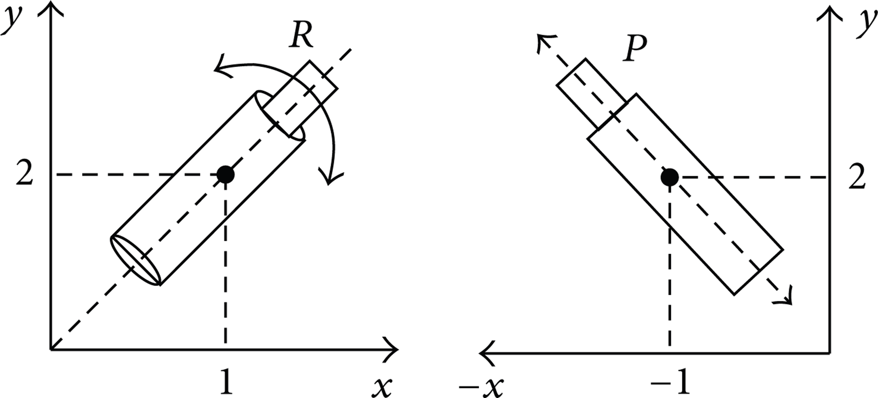
Two common planar kinematic pairs.
To better describe the configuration of kinematic pairs in space, the methods described in [14] can be modified. Figure 3 shows the rotating or translation axis OA of one arbitrary kinematic pair in space. OA is not a vector and therefore those axes similar to OA that intersect with the hemispherical surface S2 below the plane P can be expressed in the same way as those axes that intersect with the hemispherical surface S1 above the plane P. This means that all axes in space can be expressed by employing those axes in quadrants I–IV, as shown in Figure 3.
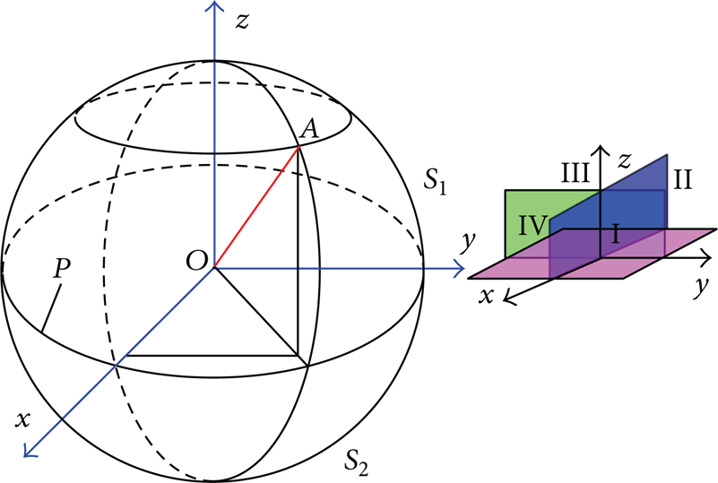
One arbitrary kinematic pair axis in space.
The modified expression of pairs is given as
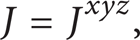
where J = {R, P, O, W, H, C, A, G, S, F}, A = {ART, ARO, ATT, ATO}, and RT, RO, TT, and TO are shown in Figure 4 [14]. R is the direction of rotation, O is the oscillation axis of the follower, and T is the direction of translation of the cam and the follower.
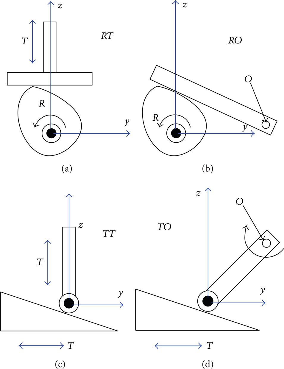
Schematic diagram for RT, RO, TT, and TO.
By replacing x, y, and z with numbers and considering three cases of kinematic pair axes in space, we obtain the following expressions.
If the axes are coaxial with the coordinate axes, the configuration of pairs can be expressed as J x , J y , and J z , where x = {1}, y = {2}, and z = {3}.
The axes of most pairs listed in [14] are coaxial with the coordinate axes and can be expressed as

If the axes are not coaxial with the coordinate axes but are in one plane, then the following cases are possible:
when the axes are in the plane xoy

and the configuration of the pairs in Figure 2 can be written as R12, P−12;
when they are in the plane xoz

and the configuration of the pairs in Figure 5(a) can be written as R13, P−13;
when they are in the plane yoz

and the configuration of the pairs in Figure 5(b) can be written as R−23, P23.
If the axes are not coaxial with the coordinate axes nor in one plane, then

and J is written as J123 if the axes are located in quadrant I, J−123 if located in quadrant II, J−1 − 23 if located in quadrant III, and J1 − 23 if located in quadrant IV.

Revolute and prismatic pairs located in different planes.
When x = ∞, y = ∞, and z = ∞, this type of code denotes the pairs with no defined configuration in space and the direction of the axes is arbitrary. This corresponds to the spherical pair described in [14], which can be expressed as

3. Method for Describing Changes to Links and Pairs
The number of links and pairs, as well as their configuration, will be changed during the metamorphic process; this case belongs to the category of metamorphic mechanisms [15] and will be described in further detail below.
3.1. Method for Describing a Change in the Number of Links and Pairs
In mechanisms, links are connected by pairs; therefore, the number of pairs will increase or decrease with any change in the number of links.
3.1.1. Method for Describing a Decrease in the Number of Links and Pairs
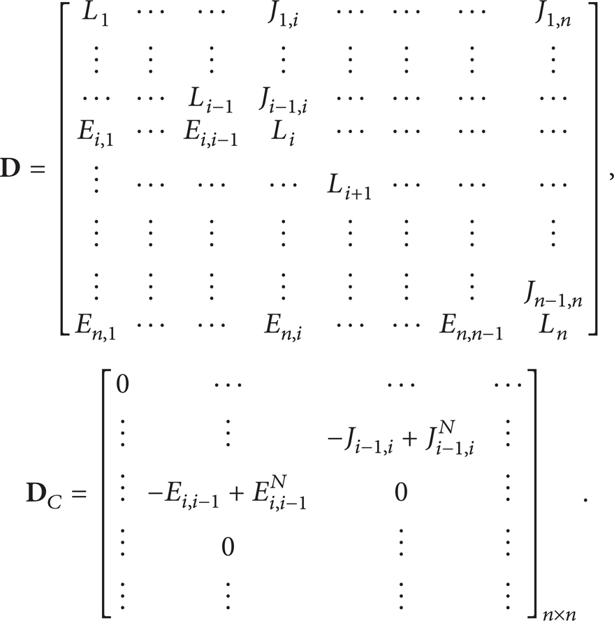
A planar 5-link mechanism can be seen in Figure 6(a); links are connected with each other by means of revolute pairs whose axes are parallel to or coaxial with the x-axis. The circles denote links and the lines denote pairs, while the subscript of the pair code (such as 4 in R41) denotes the position number in the figure. If the 5-link mechanism is folded into one 4-link mechanism (with one link and one pair losing their function), then this transformation can be expressed as

where the diagonal elements denote the link numbering, the upper triangular elements are the pair type, and the lower triangular elements are the feature of kinematic pairs.

Starting and ending points of transformation of a 5-link mechanism into a 4-link mechanism.
3.1.2. Method for Describing an Increase in the Number of Links and Pairs
Mitosis, which is used to complete the duplication of DNA molecules and the related synthesis of proteins, is one of the most important division modes of cells. Two main steps are included: the first one involves duplicating the genetic material of a cell, and the second one divides the cell into two cells with the same amount of genetic material in each cell [16–18].
Therefore, referencing the process for mitosis, the process for an increase in the number of links and pairs can be described as follows.
Disconnect a pair which connects two links in one mechanism.
Duplicate one more link than the desired number of links, plus the corresponding pairs.
Connect these duplicated links with pairs.
Delete one link according to the method mentioned in Section 3.1.1.
Figure 7 demonstrates the process for transforming a planar 4-link mechanism into a planar 5-link mechanism [19, 20].

Example of process for increasing the number of links and pairs: (a) start with 4-link mechanism; (b) disconnect link 1 from link 4; (c) add links 5 and 6; (d) add corresponding pairs; (e) merge link 6 into link 5; (f) finish with 5-link mechanism.
3.2. Method for Describing a Change to the Features of Kinematic Pairs
Changes to the features of pairs include changes in pair type as well as in the geometric relationship of the pairs. Modifying the pair type means replacing an existing pair with a different kind of pair, as shown in Figure 1(b); changing the geometric relationship means altering the configuration in space of a pair.
The connecting relationship among links in one topological graph can be written in the form of an adjacency matrix as follows:

where L
i
(1 ≤ i ≤ n) is the number of each link in one kinematic chain,
Changing the type of a kinematic pair means deleting the existing pair and adding a new one. The operation is written as (− Ji − 1, i + Ji − 1, i N ), in which Ji − 1, i represents the pair before the change, and Ji − 1, i N indicates the pair after the change. If the two pairs to be exchanged are the same, they can be added or subtracted directly (giving a value of zero), as shown in these examples:

Changing the geometric relationship of kinematic pairs means deleting the existing pair configuration and adding a new one. Similar to the above, the operation is expressed as (Ei − 1, i + Ei − 1, i N ), where Ei − 1, i represents the pair before the change and Ei − 1, i N indicates the pair after the change. Except for element 0 in the lower triangular matrix, if the two pairs to be exchanged have the same geometrical relationship, they can be added or subtracted directly, as shown here:

After a feature change to a kinematic pair, the connecting relationship among links and pairs can be expressed as

where
As can be seen in Figure 8(a), when the coordinate of the kinematic chain is established and each link is numbered, the adjacency matrix for links in this chain is

Schematic diagram for kinematic pair change.
As shown in Figure 8(b), when the revolute pair between links 3 and 4 is replaced by a prismatic pair, both the pair type and geometrical relationship are changed. Hence, the changed adjacency matrix for the links is

where

3.3. Method for Describing Kinematic Chain Fusion
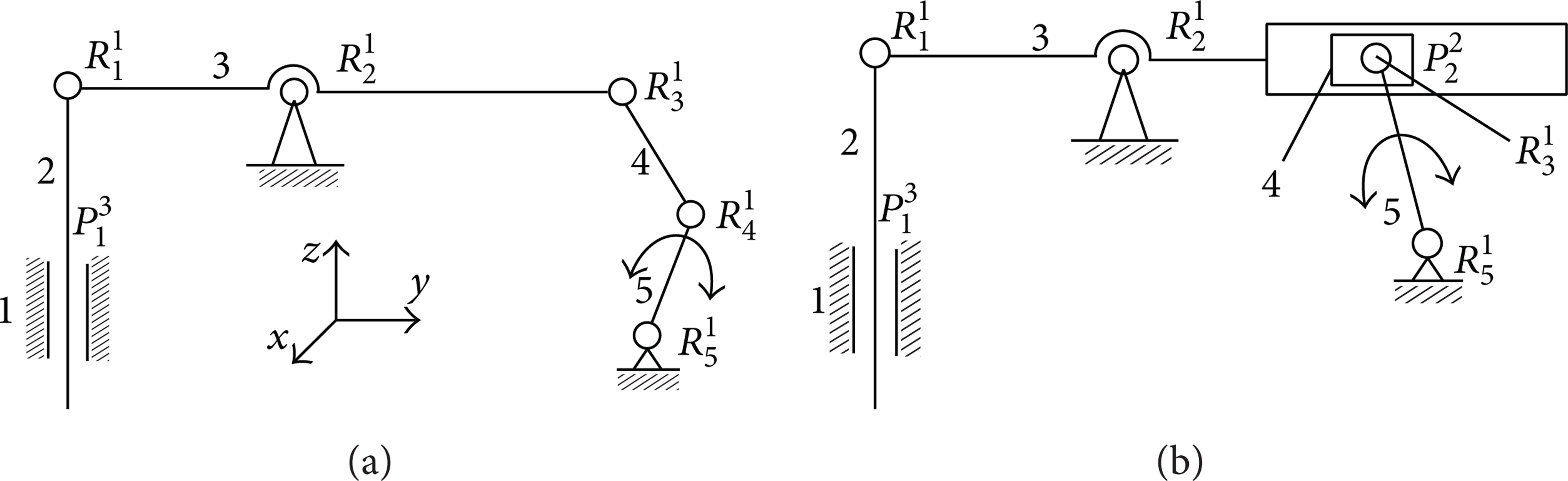
In sexual reproduction, cell fusion is the basis for creating a new individual. The fusion mechanism is that two or more cells with different genes are merged into one cell under natural or artificial conditions (biological, physical, and chemical). The basic process in which two cells are merged into one cell is shown in Figure 9 [21].
Schematic diagram of cell fusion.
Similar to cell fusion, the generation of a new mechanism needs some different basic units that are connected well to achieve the desired functions. In mechanical design, a kinematic chain is composed of several links, which are connected with pairs. If we call each link directly connected by pairs a BCU, then a kinematic chain involves the fusion of several BCUs under specific conditions. The kinematic chain is then given by
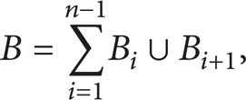
where B is the kinematic chain and B i and Bi + 1 are the BCUs.
One kinematic chain can be divided into two parts: one is the collection of links and pairs that will be fused with other chains, and the other is the collection of links and pairs that will remain unchanged. Therefore, one kinematic chain with these two parts can be expressed as

where ∑j = 1 n J i denotes the collection of all pairs, “–” denotes one link, and J i − Ji + 1 is the combination in which links and pairs will be fused.
The Fusion Condition for Chains (B i ∩ Bi + 1 ≠ ⌀). If B i ∩ Bi + 1 ≠ ⌀, then the same connecting form of BCU exists in two kinematic chains, and the two chains can be fused directly. The new kinematic chain is given by

For example, as shown in Figure 10(a), if links 1 and 4 will be fused with revolute pair R31, the expression below applies


Fusion process for kinematic chains.
However, if links 1 and 4 will be fused with revolute pair R21 as given in Figure 10(b), the kinematic chain can be written as

Figure 10 shows the fusion process, with the mechanism in Figure 10(c) being the new mechanism after the fusion operation.
4. Examples
Two examples are given here to demonstrate how the presented concepts and methods can be applied to describe mechanism folding and innovation processes.
4.1. Folding Process for a Given Mechanism
Figure 11 illustrates the metamorphic process of a folding chair which is an 8-link mechanism. Figure 11(a) is the cross-sectional view of Figure 11(b), thus links 4, 5 and 8 can be seen. The whole mechanism can be successfully folded by controlling the link dimension and the configuration of the pairs in space. This results in the mechanism having a smaller volume than the initial configuration.

Folding process for an 8-link mechanism.
The configuration in Figure 11(b) can be achieved from many initial configurations through transformations such as the one shown in Figure 12 for a common simple parallelogram. Because of space limit, the numbers 1∼8 denote links 1∼8, respectively.

Topological graphs for folding the mechanism in Figure 11.
Starting from the simple parallelogram shown in Figure 12(a), we can obtain the folded mechanism in Figure 11(b) by continuously changing links and pairs; the details are as follows.
The initial adjacency matrix of the parallelogram is

Establish an 8-link mechanism. It can be seen that the mechanism is symmetric with respect to the plane P. Duplicate links 1∼4 to obtain links 5∼8, and then add corresponding pairs which are shown in Figure 12(c); we can describe the process of change in the following form:
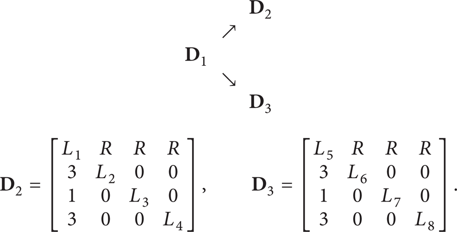
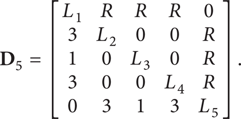
As shown in Figure 12(d), in the two kinematic chains, links 2∼4 are fused with links 6∼8 using pairs R63, R51, and R43, respectively. The chain's adjacency matrix is as follows:

Two steps are needed to fold the mechanism in Figure 11(b) into that in Figure 11(d).
Step 1. Fold link 6 onto link 2 as one link named link 2; fold link 8 onto link 4 as one link named link 4; fold link 7 onto link 7 as one link named link 3. After these operations, the adjacency matrix is
Step 2. Fold link 5 onto link 1 as one link named link 1; the new adjacency matrix is

The mechanism in Figure 11(d) loses all its freedoms at this stage, and all links are folded together as one link with a smaller volume which is convenient for transport and storage.
4.2. Innovation Process for a Parallel Mechanism
The generation of new mechanisms includes the invention of fully new mechanisms as well as innovation based on existing mechanisms. The invention of fully new mechanisms requires that the designers have more theoretical knowledge and experience and is rather challenging. However, innovation based on existing mechanisms is easier and takes less time. Therefore, this paper focuses on the latter.
Compared with serial mechanisms, parallel mechanisms have the advantages of high precision and the ability to handle heavy loads, among other things. Parallel mechanisms are therefore more widely used in the industrial field. Figure 13(a) shows a topological graph for the initial configuration of one parallel mechanism. Link M denotes the moving platform (MP) of a parallel mechanism and link F denotes the fixed base (FB). Figure 13(a) shows an example of the type of mechanism expressed by the graph in Figure 13(a). In Figure 14(a), L i (1 ≤ i ≤ 6) is a rigid link, and A j (1 ≤ j ≤ 6) is a spherical pair. The parallel mechanism in Figure 14(a) can be modified to achieve another different parallel mechanism using the following procedure.
Ignoring links M and F, break the remaining three links into six links, as shown in Figure 13(b).
Choose some pairs to connect above the broken links. Different configurations with different functions can be obtained by choosing different types of pairs.
Changing of the kinematic pairs in Figure 14(a) is optional; this is up to the designer. However, changing the pairs (including changes in pair type and configuration in space) allows for the creation of many kinds of parallel mechanisms.
Check the obtained mechanisms to make sure that all of them meet the requirements.

Topological graphs for some parallel mechanisms.

Four different parallel mechanisms.
Figure 14(b) shows one modified mechanism [19], for which L i (1 ≤ i ≤ 6) is a rigid link; A j (1 ≤ j ≤ 6) is the pair in which two revolute pairs are connected together with the axis of one perpendicular to that of the other (also called a universal joint); and B k (1 ≤ k ≤ 6) is a prismatic pair. By breaking the links between MP and FB according to the topological graphs in Figures 13(c) and 13(d) and at the same time changing those pairs that connect links with MP or FB, more complex parallel mechanisms can be obtained. Two configurations are shown in Figures 14(c) and 14(d) [22–24], one in which the pairs that connect links with MP or FB are all spherical pairs and the other in which the remaining pairs in Figure 14(d) are all prismatic pairs.
Overall, it is clear that, for mechanism innovation, aiming to find more and better configurations from another point of view, it is useful to consider gene connection and mutation as well as mitosis and cell fusion.
5. Conclusions
Kinematic pairs in mechanisms are seen as basic connecting units that are similar to the base pairs in DNA molecules, and a modified method is presented to describe the configuration of the pairs in space in the form of pair codes.
An idea is proposed to achieve many folding schemes for a mechanism. Based on this idea, one kinematic chain is first decomposed into many basic chains, and then a folding study is carried out on these chains. Finally, the chains are fused to form a complete mechanism.
Two examples are given to demonstrate the application of the proposed concepts and methods for the folding and innovation processes of metamorphic mechanisms. It is hoped that this work will provide some guidance and serve as a reference for related research.
Conflict of Interests
The authors declare that there is no conflict of interests regarding the publication of this paper.
Footnotes
Acknowledgments
This work is supported by the 973 Project (no. 2013CB035502) and the Program of Introducing Talents of Discipline to Universities (no. B07018).