
Abstract
A suction casting process for fabricating Zr55Cu30Al10Ni5 bulk metallic glass microcomponent using silicon micromold has been studied. A complicated BMG microgear with 50 μm in module has been cast successfully. Observed by scanning electron microscopy and laser scanning confocal microscopy, we find that the cast microgear duplicates the silicon micromold including the microstructure on the surface. The amorphous state of the microgear is confirmed by transmission election microscopy. The nanoindentation hardness and elasticity modulus of the microgear reach 6.5 GPa and 94.5 GPa. The simulation and experimental results prove that the suction casting process with the silicon micromold is a promising one-step method to fabricate bulk metallic glass microcomponents with high performance for applications in microelectromechanical system.
1. Introduction
Bulk metallic glasses (BMGs) with high mechanical strength, large elasticity, and excellent wear and corrosion resistance have attracted wide interests among scientists and engineers [1]. Without the limit of crystalline grain, BMGs can be formed into micro- and even nanostructures [2], and in these scales it is found that their brittle drawback could be mitigated [3]. With the above good formability and mechanical property in micro- and nanoscales, BMGs are considered to be attractive materials for microelectromechanical system (MEMS) [4].
Till now, there are two main net-shape methods to fabricate BMG components: casting process and thermoplastic forming (TPF) process [5]. In casting process, a BMG mother alloy (a homogeneous alloy ingot not in amorphous state) is melted into high temperature liquid, and then cast into a mold (usually made of copper) followed by fast cooling to avoid crystallization. This process has been widely used to manufacture BMG rods and plates [6], which are usually employed as feedstock in other process, such as TPF process and laser welding [7]. In TPF process, a BMG feedstock is reheated into metastable viscous liquid and then formed into components under a low pressure or a low strain rate before crystallization occurrs [8]. For both of these two processes to fabricate microcomponents, the micromolds are necessary and their preparation and corresponding demolding are challenging. Recently, the semiconductor process with silicon as the primary material has been well-developed, which provides a solution for these problems. The silicon micromolds have already been used in the TPF process to fabricate BMG microcomponent or structure successfully. Wang et al. formed a Zr-based BMG microspur gear with a silicon micromold using hot embossing process, where the silicon mold was prepared by inductively coupled plasma (ICP) technique and dissolved by chemical etching to release the microgear [9]. Bourne et al. fabricated a closed BMG microchannel by a novel multilayer Si stack micromolding process [10]. He et al. prepared the BMG molds based on TPF process using master silicon micromolds [11]. In these works, there are two steps to fabricate microcomponents: preparing the amorphous BMG feedstock with casting process, and then fabricating microcomponents with silicon molds by TPF process. Compared with the above processes, the casting of BMG components is one-step process, which has been reported to have a very high precision. Due to absence of a phase transition in casting process, the solidification shrinkage of the cast BMG is less than 0.5% [12], and the imprintability on the die surface can achieve nanoscale [13].
In this paper, we introduced silicon micromold into suction casting process for fabricating the BMG microcomponents from mother alloy directly. The suction casting process with silicon micromolds was simulated by finite element method (FEM), and a complicated Zr-based BMG microgear with 50 μm in module had been fabricated by the suction casting method.
2. Experimental
Silicon micromolds play an important role in the microcomponents fabrication, which are prepared by the procedure as shown in Figure 1(a). Firstly, the AZ9260 photoresist was spun coating onto a silicon wafer at 3000 RPM for 30's and patterned by ultraviolet (UV) exposure for 100's (Karl Suss MA6). Then ICP etching was conducted with Oxford PlasmaLab System 100 (Oxford Instrument, Inc.) by the use of Bosch process to transform the photoresist pattern to silicon substrate. The etching cycle for ICP process was carried out for 10's under the conditions of RF 25 W, ICP 750 W, SF6 100 sccm, and SF4 5 sccm, and the passivation cycle was carried out for 10's under the conditions of RF 20 W, ICP 750 W, SF6 5 sccm, and SF4 100 sccm. After that, the photoresist was removed by acetone and the silicon micromolds were obtained.

(a) Fabrication procedure of silicon mold: coating the photoresist, UV exposure, ICP etching, and photoresist removing; (b) sketch of the suction casting equipment with sectional view; (c) photographic image of the cast BMG with the microcomponent.
A universal suction casting equipment (WK-II vacuum arc melting furnace) was modified as shown in Figure 1(b). A copper block was fixed in the cylindrical copper mold cavity for placing the silicon micromold, and gaps were left as the suction openings. Zr55Cu30Al10Ni5 BMG mother alloy ingot of 20 g was prepared in the furnace under a titanium-gettered argon atmosphere. In order to reach a good homogeneity, the alloy ingot was remelted for 6 times by the argon arc. Afterwards, the ingot was heated into molten alloy and cast into the copper mold cavity under the suction pressure of 0.12 MPa. Meanwhile, the silicon micromold was filled with the molten alloy and the microcomponent together with the cast BMG was obtained, as shown in Figure 1(c), where the microcomponent in the silicon mold is indicated.
The redundant BMG was removed by mechanical cutting and grinding, and the silicon micromold was etched away in 40% potassium hydroxide solution at the temperature of 80°C. After that, a 50 μm in module, 40 teeth microgear with a centre hole, and five radial spokes were obtained. The appearance of the microgear was observed using scanning electron microscopy (SEM) and laser scanning confocal microscopy (LSCM), and the microstructure was characterized using transmission election microscopy (TEM). To evaluate the mechanical property, nanoindentation tests were carried out using a Berkovich tip (Hysitron TI750Ubi system), where the test load was 8 mN, and the loading and unloading rates were controlled to be 0.5 mN's−1 with an intermediate pause of 5's. Eight points were tested on the microgear and the cast BMG for comparison.
3. Finite Element Simulation
To analyze the practicability of the suction casing process for fabricating BMG microcomponent with silicon micromold, the finite element simulation was conducted by the commercial software ProCAST. As the minimum dimension in our model is about 25 μm (half of the microgear modulus), the molten alloy flow in the micromold cavity can be described by the Navier-Stokes equations [14] as follows:

where
The predefined parameters of low pressure die casting are adopted in the simulation. The filling and cooling processes of the casting and the internal stress in both of the silicon micromold and the microcomponent were investigated. The viscosity, thermal conductivity, and specific heat capacity of Zr55Cu30Al10Ni5 BMG were obtain from literatures [15–17]. The cavity was simplified and the cast microgear was modeled alone for further analysis as shown in Figure 2, where the minimum mesh size was set to be 0.01 mm. The simulation of the casting process was executed under the suction pressure of 0.12 MPa with the casting temperature of 1200°C, which was about 400°C over the melting temperature of Zr55Cu30Al10Ni5 BMG [17].
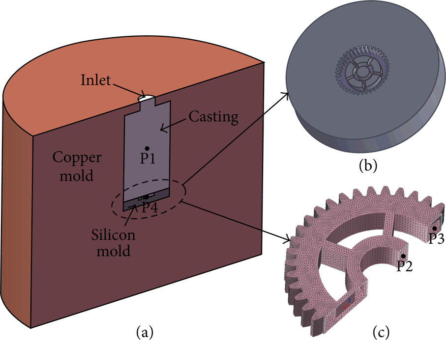
Schematic view of (a) the casting simulation model; (b) the silicon mold; (c) the mesh of the cast microgear.
The filling process of the casting can be split into three stages, as shown in Figure 3. In the first stage, the molten alloy flows into the cavity from the inlet and forms a liquid column, of which the diameter is almost the same as that of the inlet. In the second stage, the molten alloy fills into the silicon mold. Then the molten alloy fills into the rest part of the cavity in the third stage. The whole filling process finishes at about 0.0086's, with the temperature difference in the casting less than 40°C. The temperature of the silicon mold in the initial state is 20°C, and is not more than 35°C after the filling process. Thus, the entire filling process is so short that the slight temperature drop of the molten alloy can be neglected. On the other hand, the inlet plays an important role for the micromold filling. If the size of the inlet is smaller than that of the micromold cavity, the molten alloy will fill into the mold more easily and vice versa.
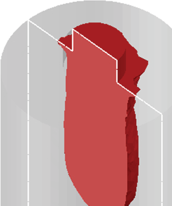
Filling process simulated by FEM with the temperature change of the cast BMG, where the initial temperature of the silicon mold is 20°C.
4. Results and Discussion
4.1. Simulation Results
The cooling of the whole casting was investigated to confirm the influence of the silicon micromold on the glass forming of the cast microcomponent. The result is shown in Figure 4. Four points in the casting were selected as shown schematically in Figure 2, where P1 is at the center of the whole casting, P2 and P3 are near the microgear center and tooth, and P4 is located in the silicon mold. The temperature of P2 is almost equal to P3, a litter lower than that of P1. The average cooling rate of the P1, P2, and P3 down to 400°C (about 20°C lower the glass transition temperature of Zr55Cu30Al10Ni5 BMG) are calculated to be 166.1°C·s−1, 170.5°C·s−1 and 170.8°C·s−1, respectively. The temperature of P4 shows that during the cooling process the silicon mold is heated to about 400°C at 1.8's and then cooled with the casting. These simulation results of the cooling process show that the temperature distribution of the cast microgear is almost uniform and its cooling rate (such as P2 and P3) is faster than the casting center (P1), indicating that the silicon micromold does not obstruct the glass forming of the cast microgear.
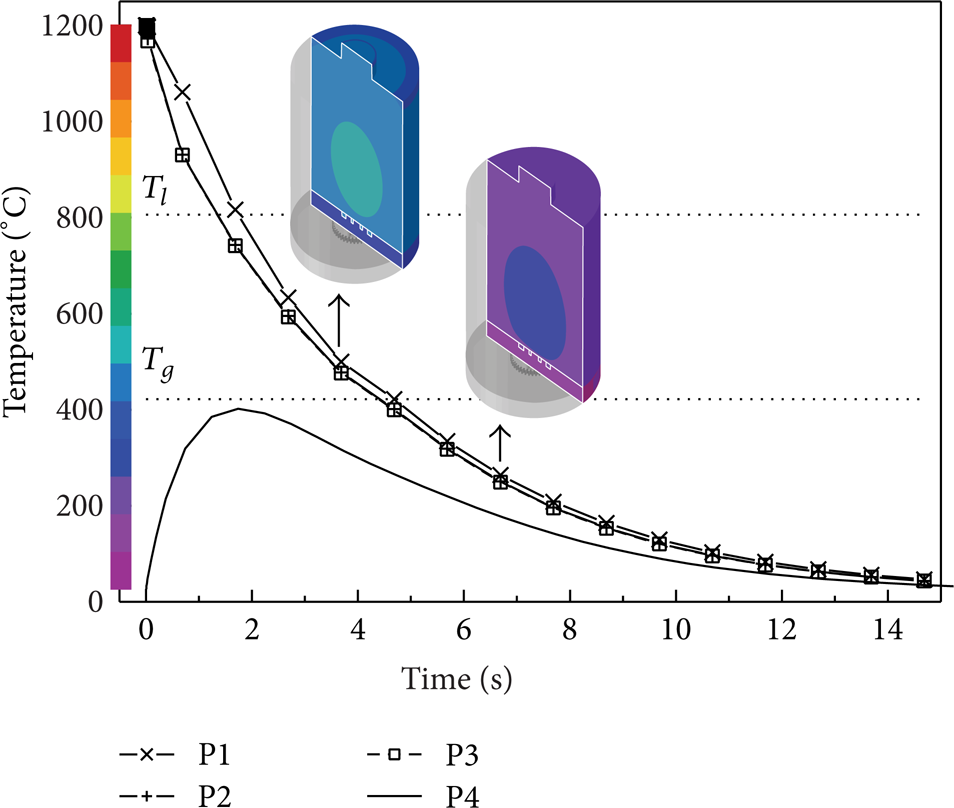
The cooling process of the four points, P1, P2, and P3 in the cast BMG or near the microgear center and tooth and P4 in the silicon mold.
The simulation analysis on the internal stress, induced by the fast cooling in the silicon micromold and cast gear, is shown in Figure 5. The maximum equivalent stress in the silicon mold concentrates around the gear teeth (1.2 GPa), lower than the silicon's theoretical strength (7 GPa). As the actual strength of the silicon micromold could be reduced by ICP etching process, there is a possibility for the cracks generating around the gear teeth on the silicon micromold. Also the average equivalent internal stress in the cast microgear is about 150 MPa, which could have an impact on its mechanical property.

Stress distributions of (a) the silicon micromold and (b) the BMG microgear.
4.2. Suction Casting of the BMG Microgear
Figures 6(a) and 6(b) show the SEM images of the silicon micromold prepared by the ICP etching process and the cast BMG filling in this mold. It can be observed that the silicon micromold has been filled by the BMG completely, and no discernable gap between them is noted except a ring crack at the outermost edge of the gear around the teeth tips, a good match with the internal stress simulation analysis. The crack is found being disconnected with the width of 2 μm, as shown in Figure 6(c). The SEM image of the cast microgear after released from the mold is displayed in Figure 6(d), along with its TEM image (the bottom-right of the inset) and selected-area electron diffraction (SAED) pattern (the top-right of the inset). It can be seen that the cast microgear has a clear contour profile and vertical sidewall without obviously disfigurement. The TEM image indicates that the microstructure of the gear is homogeneous and amorphous, confirming that the usage of silicon micromold will not obstruct the cast microcomponent's glass forming. The amorphous microstructure of the microcomponent is further affirmed by the SAED pattern with the typical diffuse halo ring.

SEM image of (a) the silicon mold; (b) the silicon mold filled with BMG, where the discrete ring cracks appeared around the teeth tips of the microgear. The part in the dark dashed frame was observed by LSCM; (c) the cracks between BMG gear teeth and silicon mold with the magnified image in the inset; (d) the cast BMG microgear after removing the silicon mold, along with its TEM image (bottom-right of the inset) and SAED pattern (top-right of the inset).
To check the fillability of the casting process, the surface profile of the cast BMG microgear indented by the dark dashed frame in Figure 6(b) was measured by LSCM and compared with that of the silicon micromold. The results were shown in Figures 7(a) and 7(b). For quantitative evaluation, the section profiles on the silicon mold and the cast gear were shown in Figure 7(c), where the section profile of the silicon mold was presented by a dashed curve while the cast gear was presented by a solid curve. There is a high coincidence between the two curves, with the fillability of the cast BMG into the silicon micromold up to 99.4%. This result proves that the cast BMG gear has replicated the silicon micromold successfully.

LSCM images of the part of (a) the silicon mold, (b) the cast microgear, and (c) their contours in the positions indicated in (a) and (b).
Furthermore, the sidewalls of the cast gear teeth and the center hole compared with the silicon mold were observed using SEM. Figures 8(a) and 8(c) exhibit the details of the silicon micromold, and Figures 8(b) and 8(d) present the cast microgear. There are two curves on the silicon mold that caused by ICP etching process. As marked by the white arrows, these two curves have been duplicated on the cast microgear clearly. This indicates that the cast BMG performs good replication on the silicon micromold surface in the suction casting process, despite of the microcracks occurred on the silicon mold (as shown in Figures 6(b) and 6(c)). In addition, the consistent between the positions of these curves also illustrates that the cast BMG has completely filled into the silicon micromold cavity.

SEM images of (a, c) details of the silicon mold and (b, d) the corresponding details of the cast microgear.
As mentioned above, the high precision of the cast microgear was observed despite of the difference in the coefficient of thermal expansion between Si and Zr-based BMGs. During the fast cooling process, the silicon mold was heated up to 400°C when the BMG cooled to about 700°C (as shown in Figure 4), similar to that in the TPF process. The reaction between Si and BMGs presented in the TPF process will occur in this casting process, which will hinder the shrinkage of the BMG microcasting during the following cooling process [18]. There is no gap observable between the silicon mold and the casting (as shown in Figure 6(c)) except the ring crack. Besides, the microgear is fabricated under negative pressure in the suction casting process, and there is little air in the mold cavity. In the experiments, no pores were observed in the casting microgear during grinding the redundant BMG away. Therefore, the cast microgear with high precision and low porosity is obtained.
4.3. Mechanical Property
The nanoindentation hardness and elasticity modulus of the cast microgear compared with the cast BMG excluding the microcomponent are shown in Figure 9. The average hardness and elasticity of the cast microgear are about 6.5 GPa and 94.5 GPa, a slight decrease (about 90% of the cast rod 7.2 GPa and 108.4 GPa) because of the internal stress was caused by the fast cooling. This proves that introducing the silicon micromold in the suction casting of BMG can fabricate microcomponents with good mechanical property for the MEMS applications.

Nanoindentation results of the cast BMG and the gear: (a) indentation hardness; (b) elasticity modulus.
5. Conclusions
Fabricating Zr-based BMG microcomponents by the suction casting process with silicon micromold has been studied. The simulation results forecast that the utilization of the silicon micromold in suction casting process can satisfy the fast cooling condition for the glassy forming of the cast Zr-BMG microgear. The internal stress on the silicon micromold concentrates around the gear teeth up to 1.2 GPa, which may cause cracks as the actual strength of the silicon mold is reduced by the ICP etching process. The average casting stress of the microgear (150 MPa) may influence its mechanical property. Using the silicon micromold prepared by the ICP etching process, a complicated microgear with 50 μm in module is obtained by suction casting. The discontinuous microcracks of 2 μm in width are noted around the gear teeth on the silicon mold, the amorphous state of the cast microgear is confirmed by TEM, and the mechanical property (6.5 GPa in nanoindentation hardness and 94.5 GPa in elasticity modulus) is slightly lower than the cast BMG rod (7.2 GPa and 108.4 GPa), verifying the above-mentioned simulation results. In spite of the microcracks on the silicon micromold and the casting stress, the cast gear is discovered having a high fillability of 99.4% as well as a good surface replication on the silicon micromold. These results prove that the suction casting of BMG using the silicon micromold is a promising one-step method to fabricate microcomponents with high performance for MEMS applications.
Conflict of Interests
The authors declare that there is no conflict of interests regarding the publication of this paper.
Footnotes
Acknowledgment
The authors gratefully acknowledge the financial supports of National Nature Science Foundation of China (Grant nos. 51175210, 51175211, and 51222508).