
Abstract
This work presents a numerical study of the thermal performance in a shell and tube phase change heat storage unit. Paraffin wax as phase change material (PCM) is filled in the shell space. The heat transfer fluids (HTFs: air and water) flow through the tube and transfer the heat to PCM. A mathematical model involving HTF and PCM is developed to analyze the thermal performance of the phase change heat storage unit and is validated with experimental data. Numerical investigation is conducted to evaluate the effect of HTF inlet velocity on the HTF outlet temperature, Nu, and melt fraction when air or water is used as HTF. Results indicate that the air inlet velocity has a great effect on the air outlet temperature and heat transfer rate, and the water inlet velocity has little effect on the water outlet temperature. The investigated results can provide a reference for designing phase change heat storage system.
1. Introduction
Phase change heat storage is a promising way to store energy due to the advantages of high energy storage density and constant temperature. The shell and tube phase change heat storage system has the characteristics of a large amount of phase change material (PCM) per unit volume and low heat loss and is currently the most widely used one of thermal storage modes. In the shell and tube latent heat storage device, the heat is transferred from heat transfer fluid (HTF) which flows in the tube to PCM which is filled in the shell space and the heat is stored or released by the melting or solidification of PCM. A number of studies on the thermal behavior of the shell and tube phase change heat storage system have been conducted by several researchers [1–6].
Trp et al. [7, 8] established a mathematical model to analyze the transient heat transfer phenomena of melting and solidification of paraffin wax in a cylindrical shell. They concluded that the operating conditions and geometric parameters should be chosen carefully to optimize the thermal performance of the storage unit. Gong and Mujumdar [9] developed a finite element model to study the thermal behavior of a phase change heat storage unit with water flowing through the tube and PCM placed outside the tube. The characteristics of two operation modes were compared based on the model. Long [10] performed a numerical and experimental investigation of a phase change heat storage unit involving a triplex concentric tube. A simple numerical method according to conversation of energy, called temperature and thermal resistance iteration method, was developed to analyze the solidification and melting of PCM in the triplex concentric tube. The numerical results correlated well with experimental ones. Adine and Qarnia [11] presented a numerical study of a latent heat storage unit consisting of a shell and tube. Two PCMs were filled in the shell space, and water flowed through the inner tube to transfer heat with PCMs. A mathematical model based on the conservation energy equations was developed and validated with experimental data. Several numerical investigations were conducted in order to compare the thermal performance of the latent heat storage unit using two PCMs and a single PCM. Akgün et al. [12] conducted a series of experiments to investigate the effect of increasing the HTF inlet temperature and flow rate of the shell and tube phase change heat storage unit using paraffin as PCM. The results showed that the melting time was decreased approximately 30% and low HTF flow rate was suggested for lower energy consumptions. Next, the same authors [13] analyzed experimentally a novel shell and tube phase change heat storage unit consisting of a conical shell which was filled with PCM and a tube through which the HTF flowed. The results showed that tilting the outer surface of storage container could achieve thermal performance enhancement.
In the present study, a mathematical model is developed to simulate the heat transfer process of a shell and tube phase change heat storage unit. The model is simplified by some assumptions and validated by the experimental data of reference literature. Based on the mathematical model, the thermal performance of phase change heat storage unit with different fluids as HTF is studied.
2. Mathematical Model
Figure 1 is the schematic of the phase change heat storage unit. The unit consists of an inner tube and an outer shell. HTF flows through the inner tube and exchanges heat with PCM arranged between the tube and shell. The tube radius, shell radius, and length of the heat storage unit are r i , r o , and l, respectively.

Schematic of the phase change heat storage unit.
2.1. Assumptions
In order to simplify the mathematical model, the following assumptions are made.
The PCM is homogenous and isotropic.
The flow of HTF is Newtonian, incompressible, and a fully developed dynamically laminar flow.
The heat resistance of the tube wall is negligible due to the high thermal conductivity of metal.
The thermophysical properties of PCM and HTF are independent of temperature, but those of liquid and solid PCM are different.
The heat loss of the unit is negligible, which means that the outer surface of the shell is thermally insulated.
The axial conduction of HTF and PCM is negligible.
2.2. Governing Equations
According to the above assumptions, the two-dimensional equations for HTF and PCM are expressed as follows.
For HTF:
continuity equation:
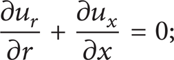
momentum equation:
r direction:

x direction:
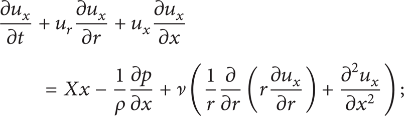
energy equation:
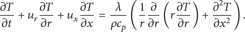
For PCM:

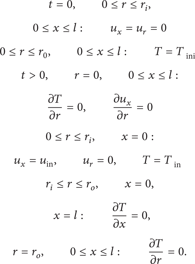
2.3. Initial and Boundary Conditions
Initially, the velocity of HTF is 0 and the temperature of HTF and PCM is Tini. The outer wall of the shell is thermally insulated. The velocity and temperature gradients of HTF at the center of the tube are 0.
The initial and boundary conditions for the unit are written as
2.4. Numerical Computations
The commercial software, FLUENT, which employs the finite volume method and uses the enthalpy-porosity formulation, is used to solve the governing equations subject to the initial and boundary conditions. The geometric model of the phase change heat storage unit is drawn and meshed in the software, Gambit, and then exported to FLUENT.
The quadratic upwind differencing scheme is used for solving the momentum and energy equations and the pressure staggering option scheme is adopted for the pressure correction equation. SIMPLE algorithm is used for pressure-velocity coupling. The under-relaxation value factors for pressure, velocity, energy, and liquid fraction are 0.3, 0.2, 1, and 0.9, respectively.
2.5. Validation
In order to verify the reliability of the mathematical model, the numerical results are compared with experimental data. The experimental unit consists of two concentric tubes. HTF flows through the inner tube (0.0158 m diameter and 1 m length) and the annular space between tubes is filled with PCM. The temperature is measured by two thermocouples arranged in the PCM at locations 1# (x = 0.95 m, r = 0.001 m) and 2# (x = 0.51 m, r = 0.002 m). The detailed information about the experiment is given in [14]. It can be seen from Figure 2 that the numerical results are in good agreement with the experimental data.

Comparison of numerical results with experimental data.
3. Results and Discussion
In practical application of the phase change heat storage system, water and air are generally used as HTF and paraffin wax is often used as PCM. In the present study, the thermal performance of the phase change heat storage unit is investigated by studying the temporal variation of HTF outlet temperature, Nu (i.e., heat transfer coefficient), and melt fraction in melting process with water and air as HTF and paraffin wax as PCM. The thermophysical properties of paraffin wax are as follows: melting temperature: 41°C, latent heat: 140 kJ/kg, PCM thermal conductivity in solid/liquid state: 0.27/0.15 W/m·K, sensible heat capacity in solid/liquid state: 2/1.5 kJ/kg·K, and density in solid/liquid state: 916/776 kg/m3. The dimensions of the unit are r i = 1 cm, r o = 3 cm, and l = 50 cm. The HTF inlet temperature is 60°C.
3.1. The Characteristics of Phase Change Heat Storage Unit with Air as HTF during Melting Process
Figure 3 shows the temporal variation curve of air outlet temperature, Nu, and melt fraction of the phase change heat storage unit during melting process when the air inlet temperature is 60°C and the air inlet velocity is 0.2 m/s.
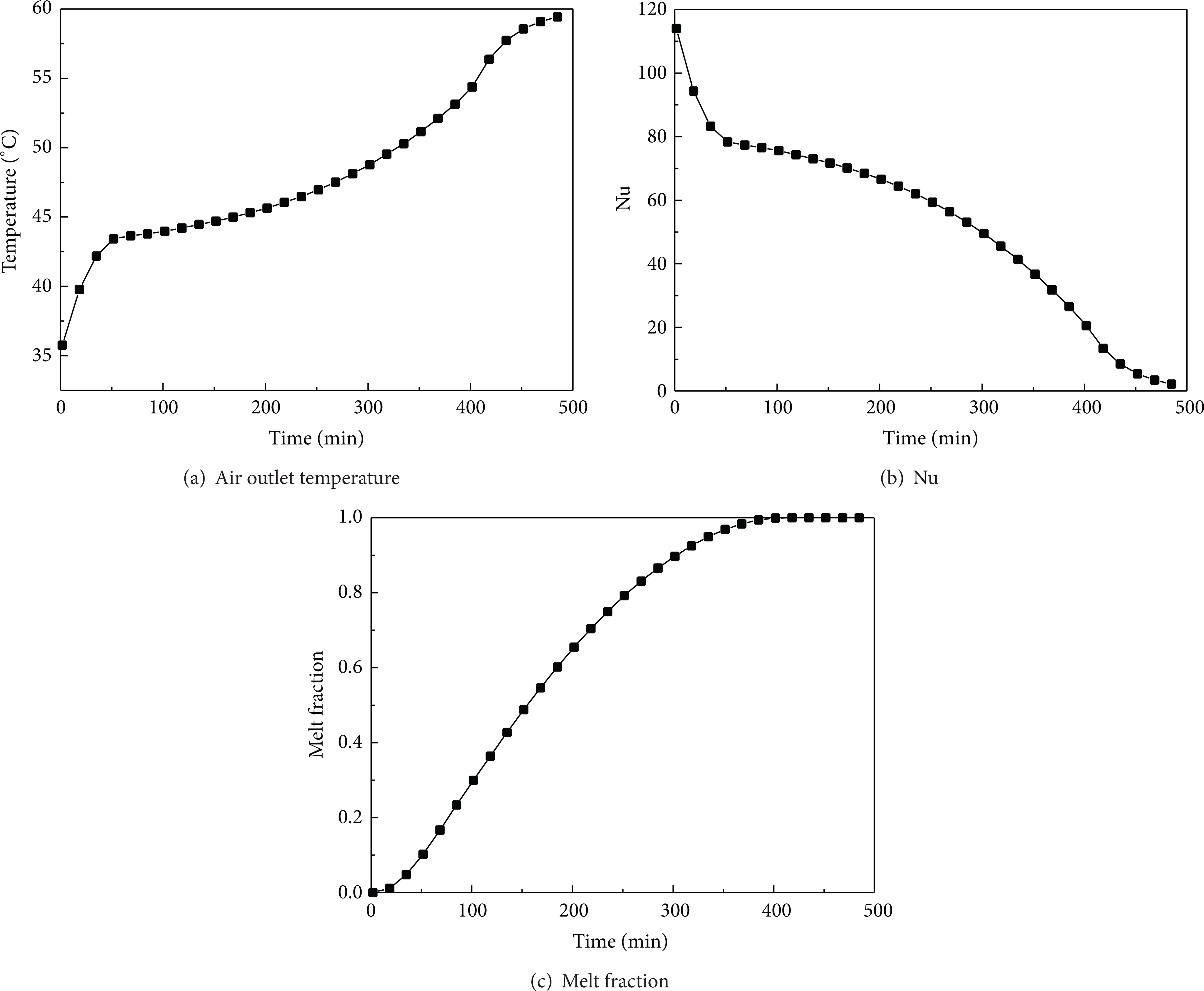
Temporal variation of air outlet temperature, Nu, and melt fraction for a given air inlet velocity, 0.2 m/s.
As can be seen from Figure 3, the melting process can be divided into three stages. At the beginning of the melting process, the air outlet temperature is low, while the Nu, which represents the heat transfer coefficient between air and PCM, is high. Then the Nu drops rapidly and the air outlet temperature rises sharply to a value slightly above the PCM melting temperature. The period mentioned above is the first stage, which is predominated by the sensible heat exchange. Although the first stage shares a small proportion of the total melting time (approximately 10%), its effect on the heat transfer rate and air outlet temperature is significant.
Next, the Nu and air outlet temperature reach a plateau, which means the heat transfer between air and PCM occurs at a relatively constant rate. This period is the second stage, in which the latent heat exchange is predominant. The second stage shares approximately 50% proportion of the total melting time and the heat transferred in this stage is the main part of the total heat consumption.
After that, the air outlet temperature rises quickly and the heat transfer coefficient between air and PCM decreases gradually. This period is the third stage, which costs a long time to store energy due to the gradual drop of the heat transfer rate. The heat exchange of the third stage is less than that of the first and second stages. So it is certainly not desirable from the engineering perspective that the phase change heat storage system works at the third stage. The shape of the heat transfer curve with the three stages of heat transfer discussed above seems to be a typical characteristic of the phase change heat storage unit with air as HTF [15]. Understanding this characteristic is important for designing a phase change heat change device which is used for an air conditioning system.
The performance of the phase change heat change unit with air as HTF depends on the air inlet temperature, inner tube radius, the amount of PCM, and the air inlet velocity. The first three factors have been given and fixed in the present study. The effect of the air inlet velocity on the performance of the unit is to be analyzed.
Figure 4 shows the temporal variation of the air outlet temperature, Nu, and melt fraction of the phase change heat storage unit during melting process subject to the varying air inlet velocity when the air inlet temperature is 60°C. It can be seen from Figure 4 that the air inlet velocity affects these factors significantly. When the air inlet velocity grows, the air outlet temperature rises, Nu decreases, and PCM melts speedily. This means, for the air conditioning system using phase change heat storage device, the desired air outlet temperature and the available time of desired air outlet temperature (i.e., the time of the first and second stage) are both restricted by the air inlet velocity. In the first and second stages, the desired air outlet temperature can be provided at an appropriate air velocity. But in the third stage, the desired air temperature and acceptable flow rate cannot be available simultaneously because the heat transfer rate is very low. So, in the practical operation, the phase change heat storage system with air as HTF should work at the first and second stages and avoid the third stage.

Temporal variation of air outlet temperature, Nu, and melt fraction for different air inlet velocities.
3.2. The Characteristics of Phase Change Heat Storage Unit with Water as HTF during Melting Process
Figure 5 shows the temporal variation of the water outlet temperature, Nu, and melt fraction of the phase change heat storage unit during melting process for different water inlet velocities when the water inlet temperature is 60°C.
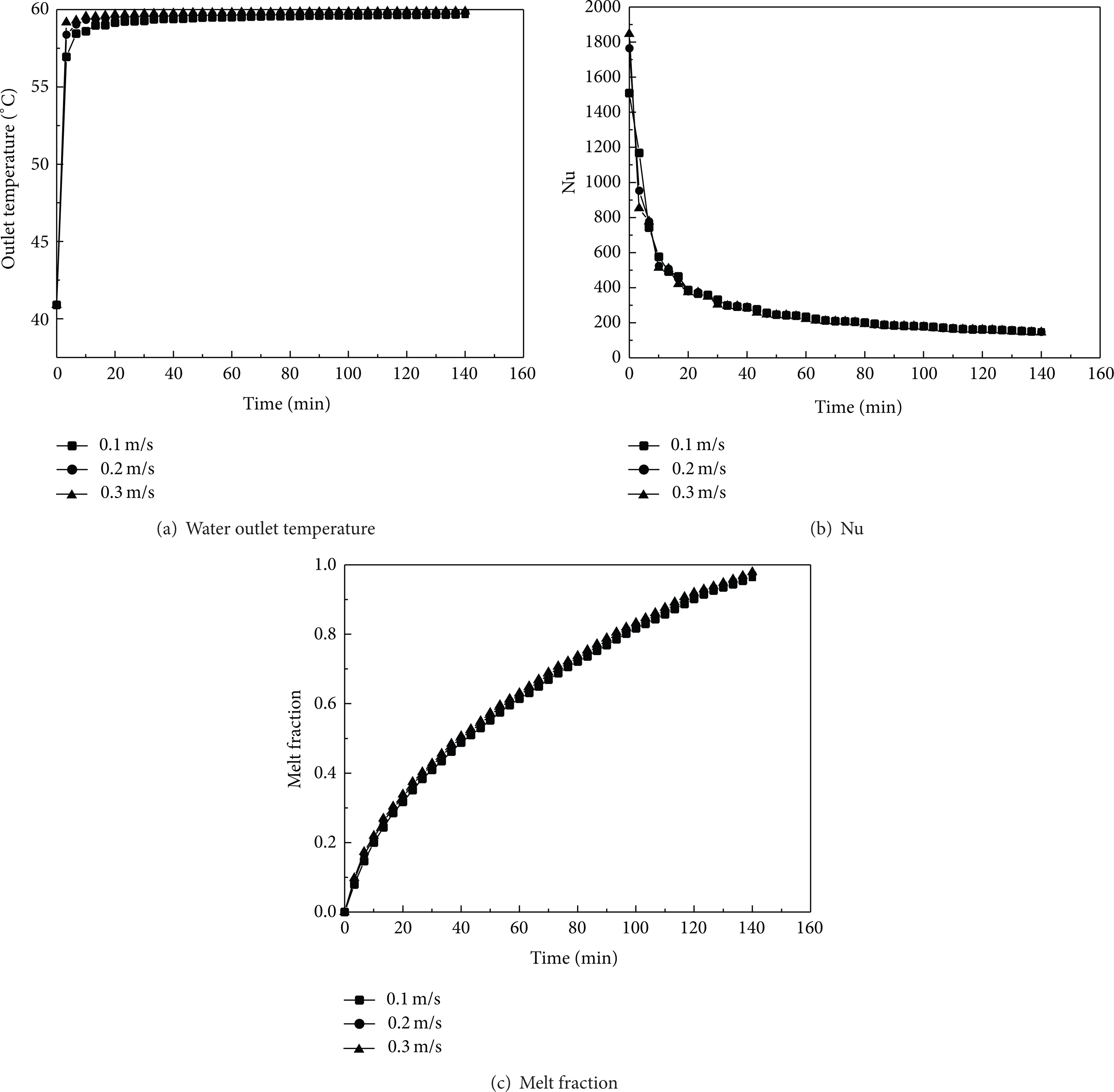
Temporal variation of water outlet temperature, Nu, and melt fraction for different water inlet velocities.
As can be seen from Figure 5, when water is used as HTF, the water outlet temperature is relatively low initially and rises rapidly to a value near the water inlet temperature. At the beginning of melting process, Nu is much larger. Then, Nu soon falls, but it is basically stable at around 200 by the end of the melting process. The melting rate also increases quickly and the complete melting time for water as HTF is much shorter than the time for air as HTF. This is because the density and specific heat capacity of water are much larger than those of air.
It can also be seen from Figure 5 that the curves of the outlet temperature, Nu, and melt fraction for different water inlet velocities are very close, respectively. This indicates that the effect of the inlet water velocity on these parameters is very small. This is because the heat resistance is mainly in the PCM side, for water as HTF, and changing the water flow rate has little effect on the overall heat transfer.
4. Conclusion
The mathematical model is developed to analyze the thermal performance in a shell and tube phase change heat storage unit and is validated by experimental data. Numerical investigation is conducted to evaluate the effect of HTF inlet velocity on the HTF outlet temperature, Nu, and melt fraction when air or water is used as HTF. The following conclusions can be drawn.
For the shell and tube phase change heat storage unit using air as HTF, the melting process can be divided into three stages. The heat exchange is relatively much in the first and second stages which take up about half the time of the melting process. The third stage is marked by little heat exchanging and long time consuming. The air flow rate has great effect on the air outlet temperature and heat transfer rate.
The heat transfer rate of the shell and tube phase change heat storage device with water as HTF is much larger than that of the device with air as HTF during melting process. The water inlet velocity has little effect on the water outlet temperature.
Footnotes
Nomenclature
Conflict of Interests
The authors declare that there is no conflict of interests regarding the publication of this paper.
Acknowledgment
The present work is supported by the Tianjin City University Science and Technology Fund Planning Project (20130425).