
Abstract
In order to study the water lubricated bearing-rotor system in seawater desalination pump, this paper is based on the coupling between the lubricating flow field and the rotor dynamics. The fluid-solid interaction (FSI) method, Rigid Body, was adopted to study the journal orbit of the bearing-rotor system under the periodic unbalancing load. The influences of geometric and working parameter to the journal orbit were combined to analyze the stability and reliability of the bearing-rotor system. The result shows that increasing the rotating speed would increase the journal whirling amplitude and the system sensitivity to the external excitation and unbalancing load were promoted; increasing the aspect ratio would reduce the journal whirling amplitude and cause the system to be more unstable; increasing the inlet pressure would reduce the journal whirling amplitude and cause the system to be more unstable; increasing the unbalancing load would reduce the stability margin and the system is easy to be unstable if obstructed; increasing the radial clearance would reduce the journal whirling amplitude and cause the system to be more unstable. The attitude angle has no influence on the journal whirling amplitude but would influence the stability of system and the value of attitude angle should not be large.
1. Introduction
The water lubricated bearing can simplify the structure of the bearing-seal-rotor system and pump, which has great significance to improve the pump efficiency and reduce the weight of pump unit. Therefore, the water lubricated bearing is widely applied in the reverse osmosis seawater desalination pump [1]. However, the low dynamic viscosity, low carrying capacity, and huge difficulty to form the hydrodynamic lubrication of the water, with the manufacturing errors, assembling errors, and uneven material, need to be addressed. Though the rotor balance test would eliminate the influence of the above factors, the residual unbalance quantity would still exist, which would produce the unbalance load with the rotor rotating and affect the stability and reliability of the bearing-rotor system.
For the research of the stability of bearing-rotor system, the rotor and carrying capacity should be combined. At present, the calculation methods of nonlinear oil film force which have broad application are based on the Reynolds equation [2–7], which mainly adopts the finite element method and finite differentia method, but it is time consuming and the influences of inertial item and oil film curvature are ignored. In recent years, with the rapid development of the computing fluid dynamics, the researcher begins to slove the N-S equations based on CFD method [8, 9] to research the complex lubrication flow field of the journal bearing. Gertzos et al. [10] adopted FLUENT to analyze the characteristic of the journal lubricated by the Bingham fluid and compared the numerical simulation result with the experimental result. Meruane and Pascual [11] obtained the free response in different rotating speed based on the bearing-rotor system built by the ADINA. The pressure distribution was compared with the expressions for short bearing, long bearing, and their harmonic combination. The numerical simulation result is very similar with the result obtained with the harmonic combination. In addition, the journal was excited by two independent sinusoidal forces in the horizontal x and y vertical directions. The journal orbit fits with the nonlinear result and the nonlinear dynamic coefficients of the journal bearing were obtained by the least mean method, which calculates displacement response through the program. Liu et al. [12] adopted the ADINA to research the elastic hydrodynamic lubrication of the complex bearing-rotor system; the cavitation in the oil film was simulated through the phase boundary condition. The result was compared and analyzed with the result in the half Sommerfeld boundary condition. In addition, the influence of bearing elastic deformation and periodic unbalancing loads to the journal orbit was analyzed. The numerical simulation result was compared with the experimental result; the comparison indicates that phase transition boundary condition can handle the cavitation in the oil film. But at present, the numerical simulations of the lubricating flow field in journal bearing based on the CFD method are almost based on the small perturbations or relative coordinate, which would not be able to be analyzed if the journal whirling orbit and bearing structure were changed.
Because of the small radial clearance of the water film, the journal orbit under the external loads calculated by the general ANSYS fluid-solid interaction method would cause the large mesh deformation and displacement. According to the problem of large mesh deformation, the ANSYS CFX developed a new FSI method: Rigid Body. This kind of FSI method sets the internal rotating wall in water film as a rigid body. It owns the advantage that the mesh remeshing could upgrade and improve the mesh quality during the calculation period. While the general ANSYS FSI method does not have the mesh remeshing technology, therefore, the large mesh deformation and displacement would affect the calculation and even stop the calculation. Above all, this paper is based on the Rigid Body, a new FSI method, to research the variation law of journal whirling amplitude and journal whirling center under the external loads for the stability analysis and optimal design of the bearing-rotor system.
2. Governing Equations
The mass and momentum equation was used to describe the flow field of water lubricated bearing, which is combined to conduct the FSI calculation with rotor dynamic equation.
2.1. Governing Equations Based on Dynamic Mesh
The continuity and momentum equation of the unsteady incompressible viscous flow in the integral form within the arbitrary control volume V of the boundary movement is

where ρ is liquid phase density, ϕ is flux, dV is the boundary of control volume V, dA is the boundary of control area A, v is the velocity vector if liquid phase, v s is the mesh deforming rate, Γ is the diffusion item, and Sϕ is the source item of flux.
2.2. Discrete Method
The time derivative item in the governing equations expressed by the first-order backward difference form is
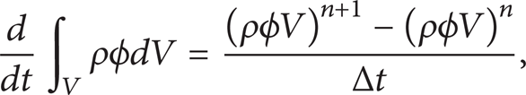
where n, n + 1 are the time in the Δt time-step during the mesh upgrading; the volume Vn + 1 in the time n + 1 is
2.3. Rigid Body Algorithms
2.3.1. Rotor Motion Equation
Consider

where Fsustain is the carrying capacity, g is the gravity, and Fext is the external excitation force.
2.3.2. Newmark Integration Scheme
The Rigid Body adopts the Newmark integration scheme which is a sophisticated integration scheme in engineering applications and universally applied in structural vibration and response analysis. Through the integration scheme to the motion equation, we can get the following equations.
Displacement:

Acceleration:

Velocity:

The Newmark integration depends on two real parameters β and λ. These parameters are directly linked to accuracy and stability of the Newmark time integration scheme. In typical applications of the Newmark method, they are chosen to be 1/4 and 1/2, respectively. This choice of parameters corresponds to a trapezoidal rule which results in a second order accurate scheme which is also unconditionally stable in linear analyses. The linear momentum equations are solved by using these parameters.
3. Bearing-Rotor System and Mesh Model
The bearing-rotor system is shown in Figure 1. In this paper we supposed that the supported rotor weight in each bearing is the same and is half of the total rotor weight. The water lubricated bearing adopts the structure of axial inlet and axial outlet. The mesh model of the water film is shown in Figure 2. The geometric parameter and working condition are shown in Table 1.
Journal bearing properties.


The bearing-rotor system.

The mesh model of water film.
The mesh model is obtained from the ANSYS ICEM. Because of the uneven scale dimension distribution in the space of axial, radial, and circumferential directions of the water film, the circumferential dimension is very small relative to the axial and radial directions. Therefore, the structure mesh with appropriate density was used to improve the calculation accuracy and reduce the calculation time. In order to obtain the appropriate mesh density, the influence of the divisions in axial, radial, and circumferential directions was analyzed. The result indicates that because the radial divisions have great influence on the result while the rest two have no obvious influence. Based on the above analysis, with considering the calculation time and ability, the final divisions or the three directions are 4 × 80 × 160(r, θ, z); the total mesh number is 65480.
The finite volume method is adapted to discrete governing equation; the first-order upwind scheme is used for continuity equation, momentum, and energy equations. Linear difference is used for the pressure difference scheme and SIMPLEC algorithm is used for pressure-velocity coupling.
The pressure boundary condition is set for the inlet and outlet. The model considers constant fluid properties, no slip on the boundaries, and incompressible and turbulent flow. The external wall of the water film is fixed.
4. Fluid-Solid Interaction
4.1. Dynamic Mesh in CFX
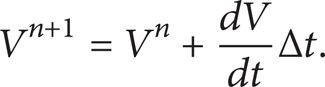
The dynamic mesh technology in CFX mainly includes the mesh motion and mesh remeshing, because the mesh can only be simply stretched and pulled, so that the mesh motion is only applied in case of the small mesh deformation and less mesh distortion. But when the large mesh deformation and displacement exist, mesh quality would be reduced and even to stop the calculation. This paper makes use of the mesh remeshing approach, which contains two methods: the user defined remeshing and ICEM CFD replay remeshing. This paper adopts the ICEM CFD replay remeshing, of which the core idea is setting the mesh quality monitor; if the mesh quality is lower than the setting value, CFX solver would recall the meshing scenario file and geometry file to remesh the grid and import the new mesh file to the CFX solver. The procedure is shown in Figure 3.
The procedure of the mesh remeshing.
4.2. FSI Calculation Method
The FSI method of ANSYS contains the general FSI method and the Rigid Body. The general FSI method mainly focuses on the influence of force from the flow and thermal field to structure deformation, which should use the solver of structure and flow field, but it is time consuming. The advantage of the Rigid Body is that it only needs to recall the solver of flow field and could update mesh quality during calculation time, which is time saving and highly efficient. The setting procedures of the Rigid Body are as follows.
Recording of the meshing scenario file of the lubrication flow field takes place, which is very important for the mesh remeshing. The meshing scenario file should be recorded very opportunely and without any modification during the recording process.
Based on the test device, the 3D model of bearing-rotor system was built and the 6-mass inertial was obtained:

The specific settings of the Rigid Body mainly contains the location, weight, 6-mass inertial, gravity, external force or torque, and 6 DOF of the rigid rotor. The internal rotating wall is set as the rigid rotor, the rotor weight is 2 kg, and the gravity direction is along the y negative direction. The rotation axis is Z and without rotation motion, so the rotational freedom degree was restricted and only with the translational freedom degree in x and y direction. For the research of the journal orbit in the periodic unbalancing loads of the paper, the external loads were excited to the rotor system which could be expressed as follows:

where M is the half weight of the bearing-rotor system, e is the unbalancing eccentricity, ω is the rotating speed; the rotor was excited by the periodic unbalancing loads along the x and y direction.
The setting for the rotating speed: since the constant changing of axial position caused by the journal perturbations, there is no fixed coordinate for the rotating speed. The CEL was used to monitor and read the axial position and journal position; the above data were used to reset the rotating speed which needs no fixed coordinate. Consider
where x and y are system variables and the coordinate value of the journal position and x d and y d are axial position, respectively, in x and y direction.
This paper adopts the ICEM replay remeshing, importing the meshing scenario file and setting the mesh remeshing.
Data monitoring and extraction: the main data of this paper are axial displacement, velocity, acceleration, and carrying capacity, all of which could be monitored in the CFX solver. Finally, the data were filtered and handled.
5. The Stability Analysis of the Bearing-Rotor System
The journal orbits importantly characterize the motion state of the rotary machine. Different journal orbits reflect different rotor motion state and the basic information of the malfunction. This chapter made the transient analysis of the water film flow field. Firstly, the stability of the bearing-rotor system was analyzed through a complete journal orbit and then the influence in the journal whirling orbits was analyzed through changing some parameters; finally, the stability of the system through the variation of journal whirling orbit was analyzed.
5.1. The Calculation of Journal Orbit
With the setting for the Rigid Body with the calculation time, boundary condition, and mesh remeshing procedure, the displacement data were used to make axial orbits by the origin. Figure 4 shows the axial orbit that inlet pressure is 1 MPa, rotating speed is 2950 rpm, unbalance eccentricity is 30 μm, radial clearance is 0.1 mm, and attitude angle is 45°. As can be seen from the figure, the shape of journal whirling orbit is oval when the journal is stable, which indicates that the bearing-rotor system is stable. This is a basis for the calculation to research the influence of rotating speed, inlet pressure, radial clearance, unbalancing eccentricity, aspect ratio, and attitude angle to the journal whirling orbit.
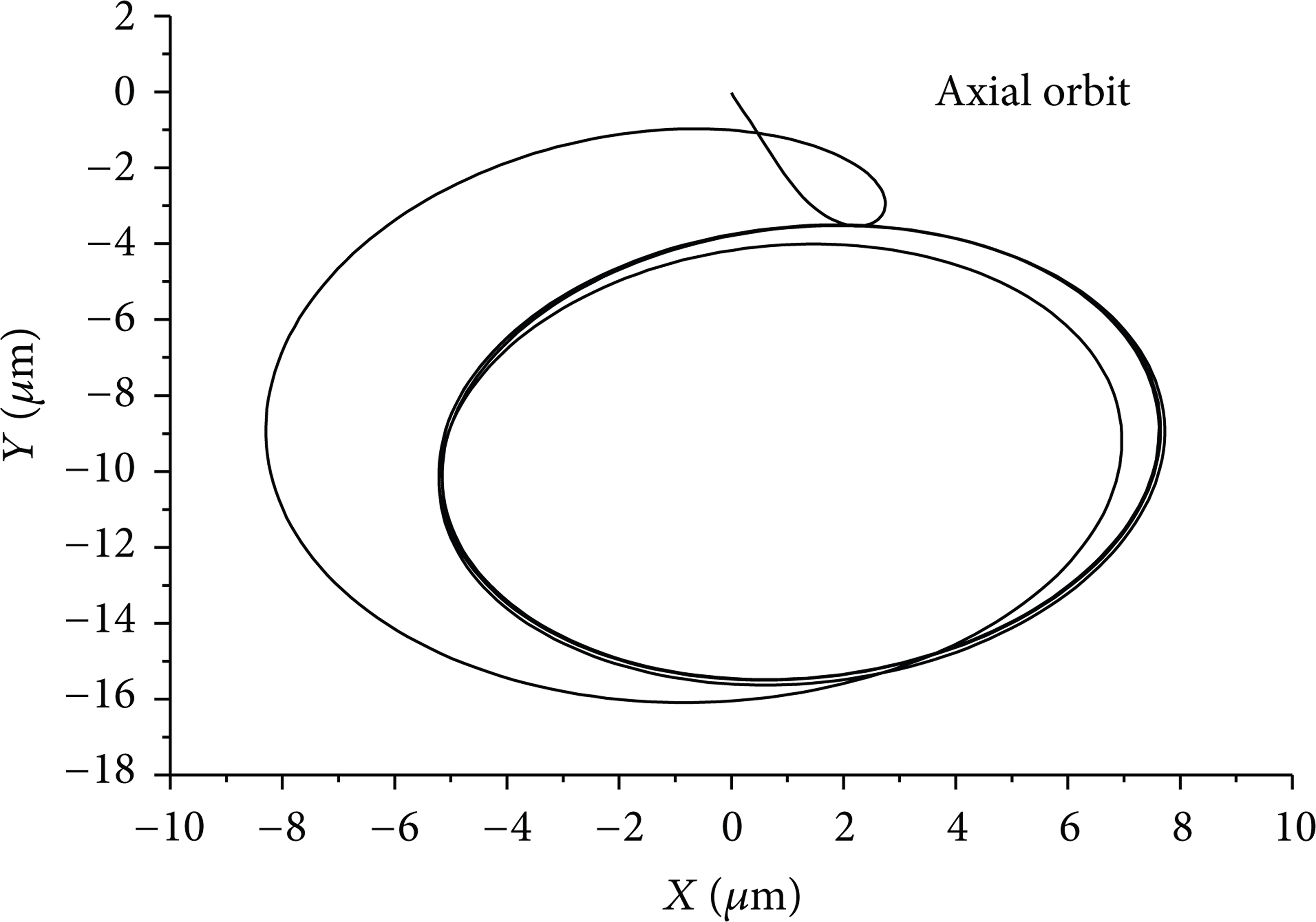
The axial orbits.
5.2. The Influence of Rotating Speed to the Journal Whirling Orbit
The journal orbit in the rotating speeds of 2000 rpm, 2500 rpm, 2950 rpm, 3500 rpm, and 4000 rpm was calculated with the other parameters unchanged. The journal whirling orbit is shown in Figure 5. With the decrease of rotating speed, the journal whirling amplitude reduces gradually. The whirling center offsets along the negative x direction and the negative y direction, while the shape of journal whirling orbit is still regular oval. This indicates that the bearing-rotor system is stable. As can be seen from the figure, the journal whirling amplitude increases with the rotating speed, which is aroused by the increase of the centrifugal force. The whirling center also moves up obviously, which is caused by the increase of the water film thickness. Increasing the rotating speed would improve the sensitivity of the bearing-rotor system to the external excitation and unbalancing loads. Therefore, in order to improve the stability margin, the requirement for the dynamic balance precision grade should be improved.
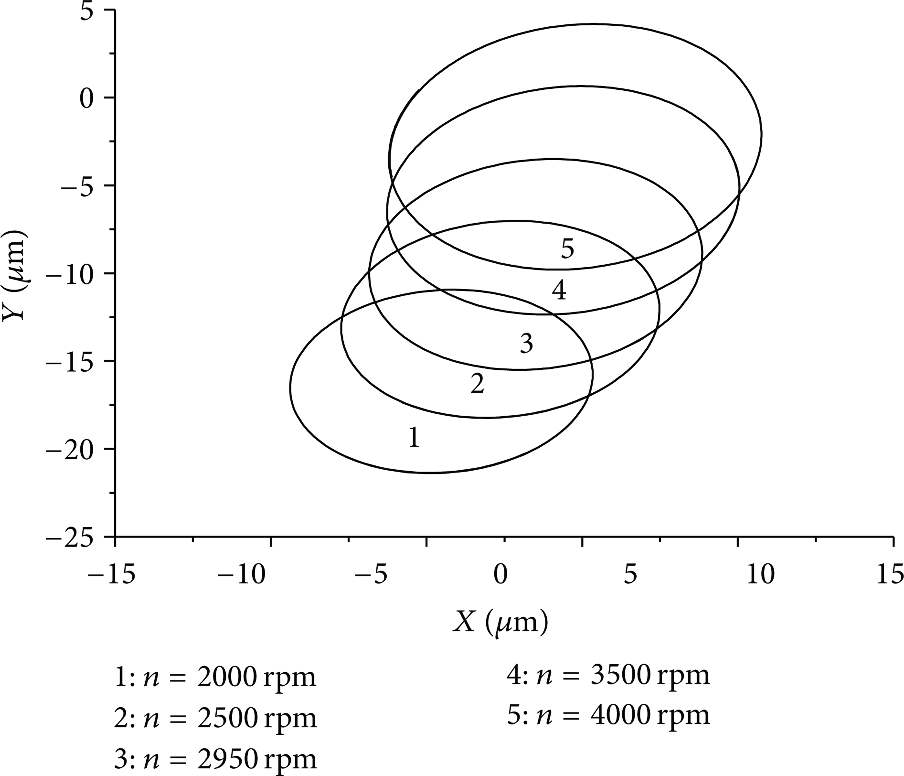
The journal orbit in different rotating speed.
5.3. The Influence of Aspect Ratio to the Journal Orbit
The journal orbit in the aspect ratios of 1.4, 1.2, 1, 0.8, and 0.6 was calculated with the other parameters unchanged. The journal whirling orbit is shown in Figure 6. As can be seen from the figure, the journal whirling amplitude reduces gradually with the increase of aspect ratio; this is due to the increase of carrying capacity. The journal whirling center offsets along the positive x direction and offsets along the y direction. The bearing-rotor system would be more unstable if the journal whirling center moves up. The aspect ratio should be taken into account for the design of the journal bearing. For the journal bearing under the low load with little carrying capacity, its axial position should be low in order to operate stably; therefore, the value of aspect ratio should be little. However, for the journal bearing under low rotating speed and high load, the value of aspect ratio should be relatively large.

The journal orbit in different aspect ratio.
5.4. The Influence of Inlet Pressure to the Journal Orbit
The journal orbit in the inlet pressures of 0.7 MPa, 0.85 MPa, 1 MPa, 1.2 MPa, and 1.4 MPa was calculated with the other parameters unchanged. The journal whirling orbit is shown in Figure 7. As can be seen from the figure, with the increase of inlet pressure, the journal whirling amplitude reduces gradually. The whirling center offsets along the negative x direction and along the positive y direction; the shape of journal whirling orbit is still regular oval. In low inlet pressure, the journal makes the substantial vibration in the static equilibrium position due to the low carrying capacity. With the increase of inlet pressure, the carrying capacity increases gradually and the journal whirling amplitude decreases gradually. Above all, increasing the inlet pressure would make the journal whirling center move up and reduce the stability of the bearing-rotor system; therefore, the selection of the inlet pressure should be taken into account.
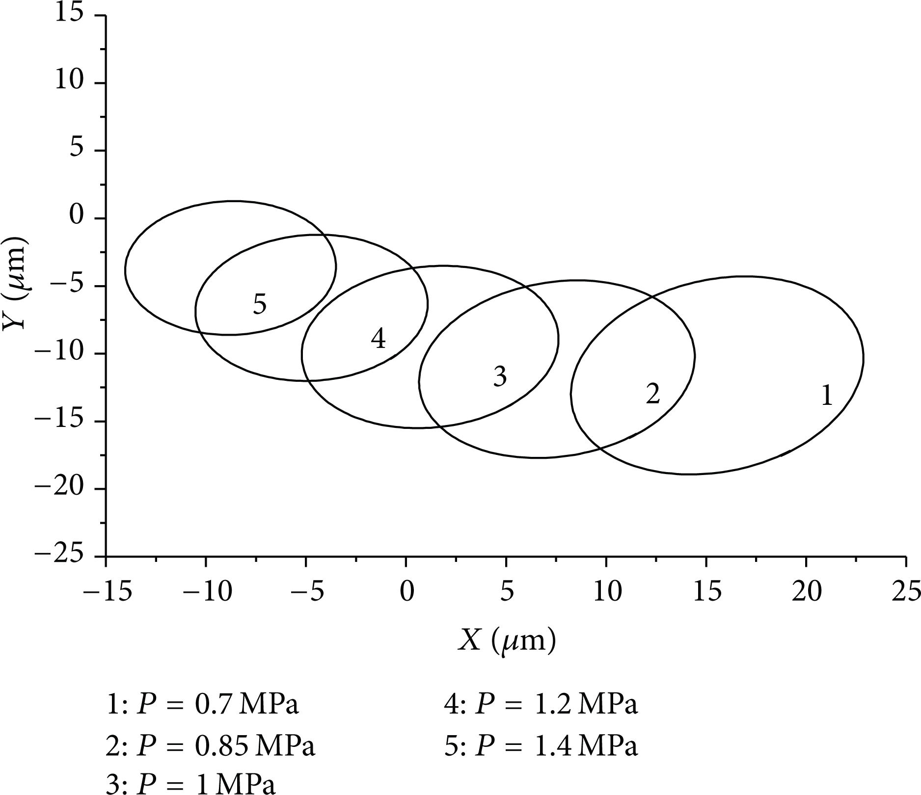
The journal orbit in different inlet pressure.
5.5. The Influence of Unbalance Eccentricity to the Journal Orbit
The journal orbit in the unbalance eccentricities of 10 μm, 20 μm, 30 μm, 40 μm, and 50 μm was calculated with the other parameters unchanged. The journal whirling orbit is shown in Figure 8. As can be seen from the figure, the journal whirls slightly in the static equilibrium position in the low unbalancing load, while the shape of journal whirling orbit is still regular oval. With the increase of unbalance eccentricity, the journal whirling amplitude increases and the journal whirling center moves up. The result indicates that the journal whirling orbit varies rapidly if the dynamic loads vary and when the rotating speed and static loads are unchanged, the journal whirling amplitude increases obviously with the increase of unbalancing load. Therefore, the unbalancing load is an important factor to influence the stability of the bearing-rotor system. Increasing the unbalancing load would reduce the stability margin. The bearing-rotor system is easy to be unstable if obstructed.
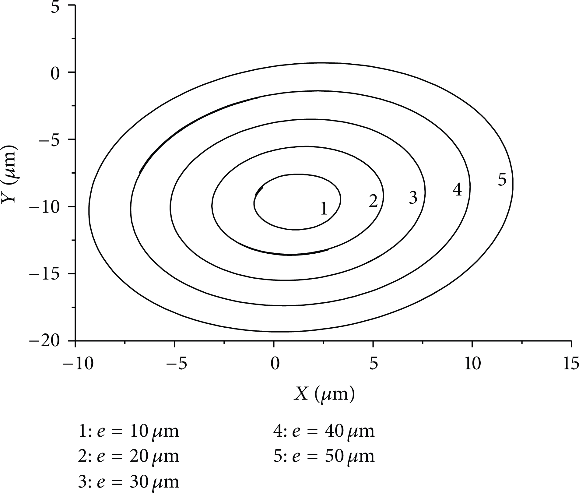
The journal orbit in different unbalance eccentricity.
5.6. The Influence of Radial Clearance to the Journal Orbit
The journal orbit in the radial clearances of 0.14 mm, 0.12 mm, 0.1 mm, 0.08 mm, and 0.06 mm was calculated with the other parameters unchanged. The journal whirling orbit is shown in Figure 9. As can be seen from the figure, the journal whirling amplitude decreases gradually with the increase of radial clearance. This is because increasing the radial clearance would increase the carrying capacity. The journal whirling center offsets along the positive x direction and positive y direction. The bearing-rotor system would be more unstable if the journal whirling center moves up. The result indicates that the radial clearance should be taken into account for the design of journal bearing. For the journal bearing under low load, it needs low carrying capacity; in order to operate stably, the axial position should be low. Therefore, the value of radial clearance should be little; otherwise, the value of radial clearance should be large.
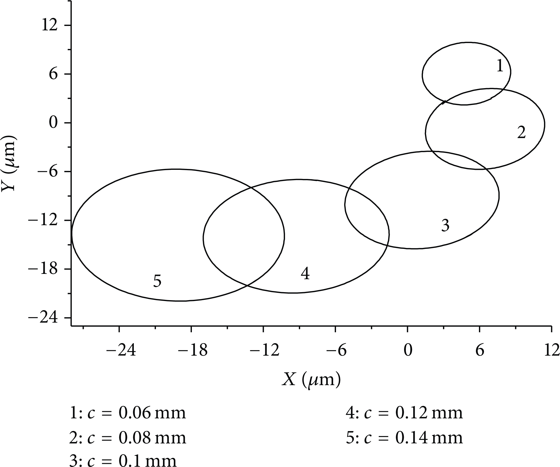
The journal orbit in different radial clearance.
5.7. The Influence of Attitude Angle to the Journal Orbit
The journal orbit in the attitude angles of 35°, 40°, 45°, 50°, and 55° was calculated with the other parameters unchanged. The journal whirling orbit is shown in Figure 10. As can be seen from the figure, the attitude angle has no influence on the journal whirling amplitude. Therefore, it also has no influence on the carrying capacity. But the journal whirling center would move up obviously with the increase of attitude angle, which would influence the stability of bearing-rotor system; therefore, the attitude angle should not be large.

The journal orbit in different attitude angle.
6. Conclusion
This paper adopts a newest FSI method, Rigid Body, to study the system coupling between the flow field of water lubricating bearing and rotor dynamic based on the mesh remeshing and makes full use of the convenience and operability of the commercial CFD software.
Increasing the rotating speed would make the journal whirling center move up right, promote the journal whirling amplitude, and raise the sensitivity of the bearing-rotor system to the external excitation and unbalancing loads. Therefore, the dynamic balance precision grade should be improved in order to raise the stability margin. Increasing the aspect ratio would decrease the journal whirling amplitude, make the journal whirling center move up, and cause the bearing-rotor system to be more unstable. Increasing the inlet pressure would decrease the journal whirling amplitude and make the the journal whirling center move up, which means the bearing-rotor system is more unstable. Increasing the unbalancing load would reduce the stability margin. The bearing-rotor system is easy to be unstable if obstructed. Increasing the radial clearance would decrease the journal whirling amplitude and the journal whirling center moves up; the bearing-rotor system is more unstable. The attitude angle has no influence on the journal whirling amplitude, but the journal whirling center would move up obviously, which would influence the stability of bearing-rotor system and the value of attitude angle should not be large.
Footnotes
Nomenclature
Conflict of Interests
The authors declare that they do not have any commercial or associative interest that represents a conflict of interests in connection with the work.
Acknowledgments
The authors are thankful for the support of the Key Project of the National Natural Science Foundation of China under Grant no. 51276083 and the National Science and Technology Support Program of China under Grant no. 2013BAB08B02.