
Abstract
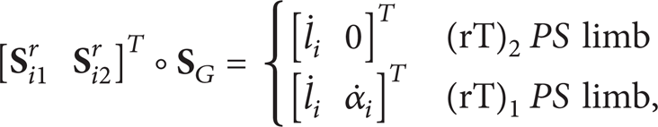
This paper presents a unified singularity modeling and reconfiguration analysis of variable topologies of a class of metamorphic parallel mechanisms with parallel constraint screws. The new parallel mechanisms consist of three reconfigurable rTPS limbs that have two working phases stemming from the reconfigurable Hooke (rT) joint. While one phase has full mobility, the other supplies a constraint force to the platform. Based on these, the platform constraint screw systems show that the new metamorphic parallel mechanisms have four topologies by altering the limb phases with mobility change among 1R2T (one rotation with two translations), 2R2T, and 3R2T and mobility 6. Geometric conditions of the mechanism design are investigated with some special topologies illustrated considering the limb arrangement. Following this and the actuation scheme analysis, a unified Jacobian matrix is formed using screw theory to include the change between geometric constraints and actuation constraints in the topology reconfiguration. Various singular configurations are identified by analyzing screw dependency in the Jacobian matrix. The work in this paper provides basis for singularity-free workspace analysis and optimal design of the class of metamorphic parallel mechanisms with parallel constraint screws which shows simple geometric constraints with potential simple kinematics and dynamics properties.
1. Introduction
Parallel mechanisms [1] have potential advantages on load-carrying capacity, good positioning accuracy, and low inertia, resulting in great interests in mechanism research aiming to produce high performance machines in applications in industry and robotics world. In order to keep these advantages of traditional parallel mechanisms [2, 3] but add additional adaptability, metamorphic parallel mechanisms (MPMs) [4] were developed. MPMs are a class of mechanisms that possess adaptability and reconfigurability to change permanent finite mobility based on topological structure change. In this paper, a class of metamorphic parallel mechanisms with parallel constraint screws are introduced and a unified singularity modelling is provided. This will be useful in optimally designing this class of parallel mechanisms which shows simple geometric constraints with potential simple kinematics and dynamics properties for practical applications.
The concept of metamorphic parallel mechanism came from metamorphic mechanisms originated from the study of decorative carton folds and reconfigurable packaging [5]. Much research work has been devoted to this area due to the novel property of reconfiguration and mobility change of metamorphic mechanisms. These include new methods to synthesize mechanisms with reconfiguration, like variable position parameters for kinematotropic linkages [6] and kinematotropic parallel mechanisms [7], metamorphic ways of changing the topological structures of a mechanism [8], screw theory based synthesis of parallel mechanisms with multiple operation modes [9], variable topology joints for variable topology mechanisms [10], and methodology for synthesis based on biological modeling and genetic evolution [11]. Following this, some research interests move to the topology description of various mobility-configurations of metamorphic mechanisms, including matrix operations [12], joint code [13], joint-gene based topological representation [14], lie displacement subgroup [15], and operation space with motion compatibility representation [16]. Other works are related to applications of metamorphic mechanisms, like metamorphic underwater vehicle [17] and metamorphic multifingered hand with an articulated palm [18]. Recently, some work has been done on metamorphic parallel mechanisms. Based on a reconfigurable Hooke (rT) joint, two types of MPMs were introduced [4] and detailed topology reconfiguration of an MPM with mobility change from 1 to 6 was investigated [19]. A general construction method for MPMs was introduced using screw theory [20] and a metamorphic parallel mechanism with ability of performing phase change and orientation switch was also proposed in [21]. In [22], motion planning for a parallel mechanism with reconfigurable configurations was studied based on lockable revolute joints.
With previous focus on the synthesis and topology representation, little work has been done on the variation of kinematics [23], dynamics, singularity, and workspace of MPMs in their reconfiguration. In this paper, a class of metamorphic parallel mechanism based on a reconfigurable rTPS limb [24] will be introduced with another focus on the unified singularity modeling and singularity change to cover all their reconfigurable topologies. In parallel mechanism research, singularity analysis [25, 26] is an important topic as singularities will make the mechanism dysfunctional and uncontrollable which should be avoided and considered before parameter design for real applications. Many methods have been proposed for singularity analysis which mainly includes Jacobian-determinant-based numerical methods [27] and Jacobian-rank-based analytical models [25]. Since this paper does not focus on a parallel mechanism with fixed dimensions, the latter one will be suitable. To investigate the Jacobian rank degeneracy, screw theory [28, 29], line geometry, and Grassmann-Cayley algebra [30, 31] were used to model the constraint and actuation forces to investigate their dependency. Based on Grassmann geometry and linear varieties from [32], Merlet [33] successfully found all the singularities of the 6-3 Gough-Stewart parallel mechanism. This method was then expanded by Hao and McCarthy [30] using screw theory with systematic analysis of possible dependent screws. Considering the variable topologies of the MPMs in this paper, screw theory shows a good way to formulize a unified Jacobian matrix [34] to include both geometric constraints and actuation constraints with the change between them in the reconfiguration while the size is kept 6 by 6.
The paper is arranged as follows. Section 2 introduces the two working phases of the reconfigurable rTPS limb with their constraint screws. The new metamorphic parallel mechanisms with parallel constraint screws are presented in Section 3 with mobility analysis, geometric design conditions, and some special topologies. Following this, Section 4 analyzes the topology reconfiguration and mobility change. Section 5 shows possible actuation scheme for variable topologies. Based on these, Section 6 proposes the unified singularity modeling and various singularity configurations with different mechanism topologies. Conclusions are made in Section 7.
2. Two Phases of the Reconfigurable rTPS Limb
The reconfigurable rTPS limb consists of a reconfigurable Hooke (rT) joint, a prismatic joint, and a spherical joint. The reconfigurability of this limb stems from the configuration change of the rT joint which has two rotational degrees of freedom (DOFs) about two perpendicularly intersecting rotational axes (radial axis and bracket axis) as in Figure 1. A grooved ring is used to house the radial axis and make it have the ability of altering its direction by rotating and fixing freely along the groove. This allows the radial rotation axis change with respect to the limb, resulting in two typical phases of the rTPS limb as in Figure 1. While in Figure 1(a), the radial axis is perpendicular to the limb (prismatic joint) which is denoted as (rT)1PS, it is collinear with the limb (prismatic joint) passing through the spherical joint center in Figure 1(b) and the limb phase is symbolized as (rT)2PS.

Two phases of the rTPS limb.
Set a limb coordinate system 1o1x1y1z at the rT joint center with 1x axis collinear with the bracket axis and 1y axis perpendicular to the bracket surface as in Figure 1(a); the twist system of the (rT)1PS limb is given as

where the first two twists are generated from the rT joint, the third is generated from the prismatic joint, and the last three are generated from the spherical joint. β is the angle between the limb (
The six screws in (1) form a six-system [35] and there is no reciprocal screw, showing that the (rT)1PS limb has six degrees of freedom (DOFs) and does not supply constraint to the platform connected to it.
For the (rT)2PS limb as in Figure 1(b), radial axis of the rT joint is collinear with the prismatic joint passing through the spherical joint center. Thus, the spherical joint center A cannot move out of the plane 1y1o1z. Based on the coordinate system in Figure 1(b), the twist system of the (rT)2PS limb can be given as

It is clear that twists

This gives a constraint force acting along a line passing through the spherical joint centre with a direction parallel to the bracket axis of the rT joint. Thus, the (rT)2PS limb has five DOFs, one less than the (rT)1PS phase.
When constructing parallel mechanisms with the rTPS limbs, the mechanisms will have ability of mobility change by altering the rTPS limbs into these two phases. In the following, the (rT)2PS limb phases will be used by connecting the rT joints to the base with parallel bracket axis and the spherical joints to the moving platform. Then altering the limbs into (rT)1PS phases will generate new mechanism topologies, which gives a class of metamorphic parallel mechanisms with parallel constraint screws.
3. 3rTPS MPMs with Parallel Constraint Screws
3.1. Mobility Analysis
From (3), it can be seen that (rT)2PS limb gives one constraint force to the platform with the direction parallel to its bracket axis. Thus, by arranging the direction of the bracket axis of the rT joint, the constraint to the platform can be represented. In this paper, the rT joints are connected to the base with parallel bracket axes, leading to parallel constraint forces expressed by screws on the platform as in Figure 2.
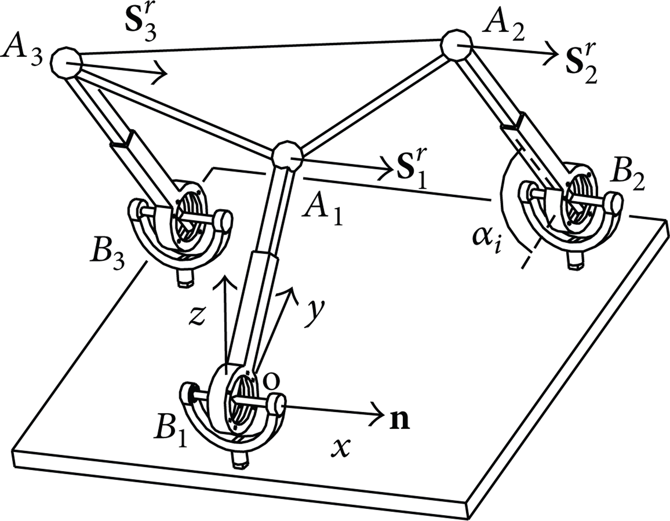
The 3(rT)2PS with parallel constraint screws.
Let points A
i
and B
i
denote the spherical joint center and the rT joint center in limb i (i = 1, 2, 3), respectively. Locate a global coordinate system oxyz at the center (B1) of the rT joint in limb 1 with x axis collinear with the bracket axis and y axis perpendicular to the bracket plane. Let
The constraint system of the 3(rT)2PS parallel mechanism in Figure 2 can be given as

where
By taking reciprocal screws to (4), motion screws of the mechanism can be obtained as
which represent three DOFs with one rotation about x axis and two translations along y and z axes.
Thus, the 3(rT)2PS parallel mechanism with parallel constraint screws has mobility three with a rotation parallel to the screws and two translations perpendicular to the screws.
3.2. Geometric Conditions of the Mechanism Assembly
Based on the geometry of (rT)2PS limb in Figure 1(b), it can be obtained that the spherical joint center cannot move out of the plane ∑ passing through the limb and perpendicular to the bracket axis (

Location condition of constraint plane ∑3.
In Figure 3, β13 is the angle between A1A3 and norm

where ϕ1 is the platform angle A2A1A3 and β12 is the angle between A1A2 and norm
Thus, constraint plane ∑3 should be located at ∑3′ or ∑3′′ or between them as in Figure 3. When it is at ∑3′ or ∑3′′, there is one intersecting point (
Here, the analysis is based on fixing points A1 and A2 by giving three actuation inputs to limb 1 and limb 2. But in mechanism actuation, normally the three inputs are given to the three limbs with one each to determine the platform displacement, which will be discussed in Section 5.
3.3. Special Topologies
When considering particular arrangements of the base and platform joints, the 3(rT)2PS parallel mechanism will have different topologies and some special cases are identified below.
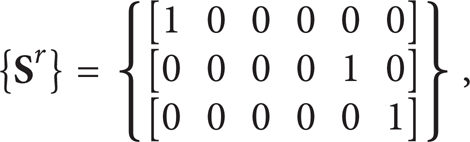
A special one is that the three spherical joint centers (A1, A2, and A3) on the platform are in line as in Figure 4(a). The constraint screws in (4) become

where l1i is the distance between points A1 and A
i
(i = 2, 3) which are all on the line with unit vector
Two special topologies.
Another special topology is that the three rT joint centers (B1, B2, and B3) on the base are in line with unit vector
Two other special topologies of the 3(rT)2PS with parallel constraint screws can be obtained when locating the rT joint center B2 on yoz plane with b2x = 0 as in Figure 5(a) and setting both rT joint centers (B2 and B3) on yoz plane with b2x = b3x = 0 as in Figure 5(b). Both topologies have two translations and one rotation and the topology in Figure 5(b) is a planar parallel mechanism.

Three more special topologies.
One more special topology can be obtained by setting line B
i
B
j
parallel to
4. Topology Reconfiguration
Altering the (rT)2PS limbs in the previous 3(rT)2PS parallel mechanisms into the phase (rT)1PS will result in various new mechanism topologies with increased mobility. After changing the phase of one limb, all the 3(rT)2PS parallel mechanisms become the topology 2(rT)2PS-1(rT)1PS in Figure 6(a) that has two parallel constraint screws following the first two in (4). Thus the 2(rT)2PS-1(rT)1PS has one constraint less and will have one DOF more than the 3(rT)2PS. Based on the constraint screw analysis, the 2(rT)2PS-1(rT)1PS parallel mechanism has four DOFs with two translations and two rotations (2R2T).

The 2(rT)2PS-1(rT)1PS topologies.
A special case is the 3(rT)2PS-e in Figure 5(c). When changing limb 2 or limb 3 from phase (rT)2PS to (rT)1PS in Figure 5(c), the mechanism changes to the case in Figure 6(a). However, when changing the phase of limb 1, the mechanism becomes topology 2(rT)2PS-1(rT)1PS in Figure 6(b) which has mobility three with one rotation and two translations (1R2T). Thus, the mechanism does not change mobility due to the structure singularity.
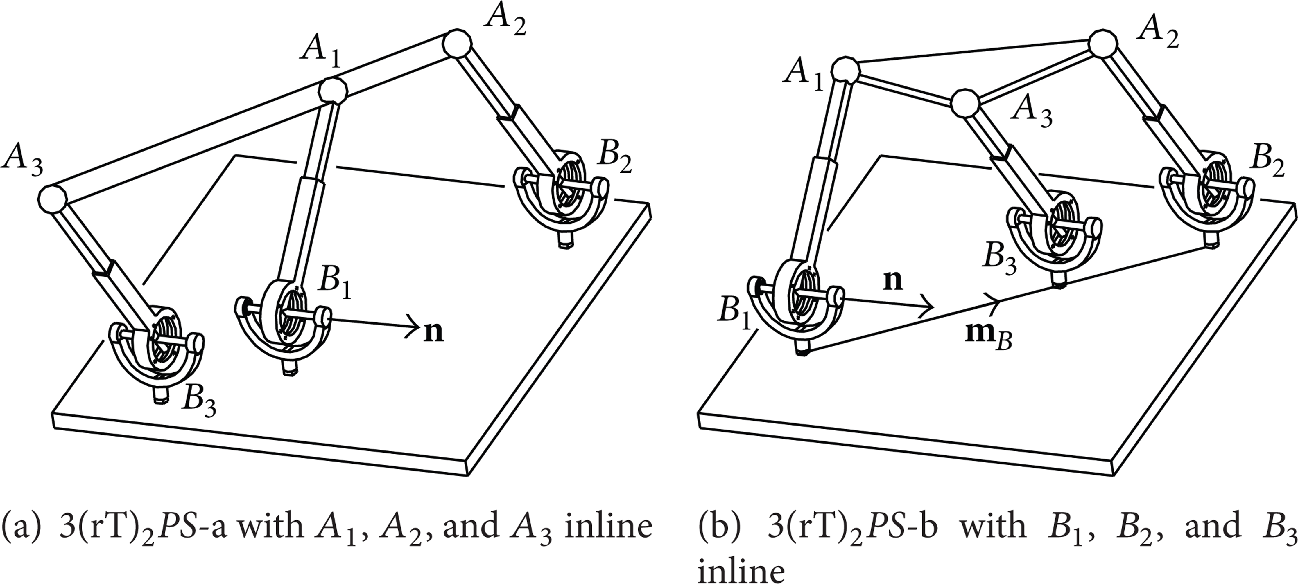
When further changing one more limb phase, both the topologies in Figure 6 change to the same topology 1(rT)2PS-2(rT)1PS as in Figure 7(a), which has one constraint screw that limited the translation along
Topologies 1(rT)2PS-2(rT)1PS and 3(rT)1PS.
When changing the third limb to phase (rT)1PS, the mechanism becomes another topology 3(rT)1PS as in Figure 7(b) that does not have any constraint screw and has full mobility 6.
One topology that should be mentioned is the 3(rT)2PS-d in Figure 5(b), in which all three limbs are constrained in one plane and it is a planar parallel mechanism. By changing the limb phases one by one, the topologies become those in Figure 6(a) and the two in Figure 7. Thus, a planar parallel mechanism becomes a spatial parallel mechanism while the mobility changes from 3 to 6.
5. Actuation Scheme for the Reconfigurable Topologies
Actuation inputs of a parallel mechanism work with limb constraints to determine the platform position and orientation. In the (rT)1PS limb, the rotation about the bracket axis and the radial axis and the translation along the prismatic joint can be selected as actuated joints. Based on Figure 8 and the limb motion screws in (1), these three inputs will result in constraint screws as

where 1

Actuation forces of the rTPS limb.
When altering the (rT)1PS limb to phase (rT)2PS, the radial axis is along the limb and the radial axis rotation cannot be an actuation input but a geometric force is produced as in (3). Based on the analysis in Section 2, the (rT)2PS phase can be taken as a special case of the (rT)1PS phase with the radial axis rotation angle β = 0. This can also be explained by the variation of the actuation forces. When giving β = 0 in (8), the actuation force from the radial axis becomes exactly the same with the geometric constraint in (3) generated in the (rT)2PS phase. Thus, the rotation about the bracket axis and the translation of the prismatic joint can be chosen as the actuation inputs in the (rT)2PS limb with expression in (8) using β = 0, which is one choice less than the (rT)1PS limb but with equivalent constraints considering the geometric constraint.
The limb actuation analysis gives the base for the mechanism actuation scheme. The 3(rT)2PS with parallel constraint screws has three DOFs and needs three actuation inputs. Based on (8) with β = 0, each limb gives two possible actuation choices and there are totally six for the three limbs. Taking three of the six actuations should constrain the three DOFs of the mechanism. For the 3(rT)2PS parallel mechanism in Figure 2, when choosing two prismatic joint inputs in limb 1 and limb 2 with a bracket rotation input in limb 3, the input constraints for the platform are

where
The three input forces in (9) with the three geometric constraint forces in (4) form a six-system, showing that the selected actuation inputs can fix the required position and orientation of the platform. Following this way, actuations for the 3(rT)2PS parallel mechanisms including the special topologies can be obtained and concluded as follows.
Any three of the six inputs (the prismatic translation and bracket rotation in each limb) can be actuations for the general 3(rT)2PS in Figure 2; the 3(rT)2PS-a, 3(rT)2PS-b, 3(rT)2PS-c, and 3(rT)2PS-d except the case that the three rT joint centers are on x axis of the 3(rT)2PS-b that cannot have three prismatic joints as the actuation.
The 3(rT)2PS-a needs three of the six inputs with an extra for the local rotation of the platform.
At least one of the three inputs should be from limb 2 for actuations of the 3(rT)2PS-e parallel mechanism.
When altering the (rT)2PS limb to phase (rT)1PS, one more actuation choice appears as the rotation about the radial axis as in (8). Based on this and the above analysis, the actuation scheme rules are as follows.
At least one of the actuations should be from the (rT)1PS limb in the reconfigured topologies 2(rT)2PS-1(rT)1PS in Figure 6 and 1(rT)2PS-2(rT)1PS and 3(rT)1PS in Figure 7.
At least two should be from the (rT)1PS limb in the reconfigured topology 2(rT)2PS-1(rT)1PS in Figure 6(b).
6. Unified Singularity Modeling and Analysis
The infinitesimal twist of the moving platform of the 3(rT)PS parallel mechanism can be written as the linear combination of instantaneous twists of each limb:

where
Based on the actuation analysis in Section 5, the translation of the prismatic joint is chosen as the input for the (rT)2PS limb and the rotation about the bracket axis is taken as the second actuation when the limb changes to phase (rT)1PS. Thus by locking the active joints in the limbs temporarily, and taking the reciprocal product on both sides of (10), for each limb there is
where
Equations in (11) for the three limbs can be rewritten in matrix form as
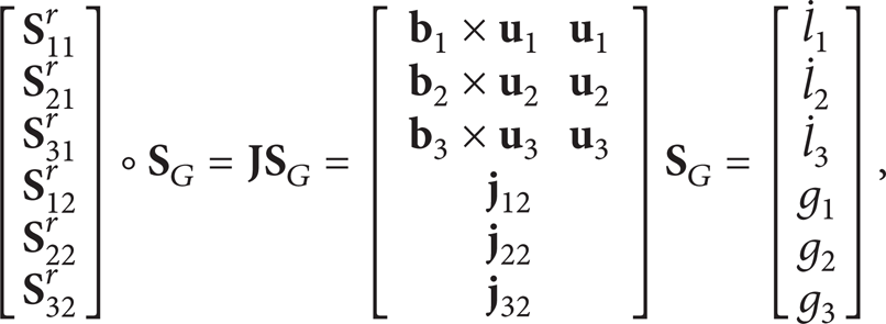
where

Thus
In general, the Jacobian matrix maps the velocities between the manipulator and the actuation input. Once the manipulator meets the singular configuration, this mapping loses its function and the rank of the Jacobian matrix decreases to be less than 6. This can also be interpreted that the six constraint forces in
6.1. Singularity of the 3(rT)2PS (3DOF)
For the 3(rT)2PS, the Jacobian matrix can be specified as

where

Singularity I.
In Figure 9, singularity I exists when the platform plane ∑A1A2A3 is parallel to the bracket axis
Another singular configuration for the 3(rT)2PS occurs when the three rotation angles (α1, α2, and α3) about the bracket axes are equal to each other, which is defined as singularity II. In this case, the three limbs are parallel to each other. Defining limb constraint plane ∑i (i = 1, 2, 3) formed by actuation force

Singularity II.
Two special cases of singularity II may exist. One is that α1 = α2 = α3 = π/2 as in Figure 10(b); the platform is parallel to the base with limbs perpendicular to them, which will never happen if the base triangle (B1B2B3) has a larger size than the platform (A1A2A3). The other one is that α1 = α2 = α3 = 0 or π as in Figure 10(c), and the platform is coincident with the base, which requires the same geometric condition for the three limbs as the singularity I configuration in Figure 9 that the third limb should be in the extreme locations shown in Section 3.2. Furthermore, these two singular configurations not only have singularity II but also include singularity I in Figure 9 as the platform plane ∑A1A2A3 is parallel to the bracket axis
6.2. Singularity of the 2(rT)2PS-1(rT)1PS (4DOF)
When changing to 2(rT)2PS-1(rT)1PS (take limb 2 to be (rT)1PS as an example), the limb 2 constraint plane changes from ∑2 to ∑2r formed by two actuation forces

Two singular configurations of the 2(rT)2PS-1(rT)1PS.
Singularity IV occurs when the limb constraint plane ∑2r is coplanar with the platform plane ∑A1A2A3. In this case, all the six constraint forces intersect at one common line A1A3 and the Jacobian matrix rank decreases to five. The manipulator has a free rotation about the common line A1A3 since all the six constraint forces cannot supply any torque to this line.
6.3. Singularity of the 1(rT)2PS-2(rT)1PS (5DOF)
When further altering to 1(rT)2PS-2(rT)1PS (limb 1 is changed), the limb 1 constraint plane becomes ∑2r formed by two actuation forces as in Figure 12(a). All above singularities may exist with this topology as it covers both 2(rT)2PS-1(rT)1PS (β1 = 0) and 3(rT)2PS (β1 = β2 = 0). One more singularity occurs when limb constraint planes ∑1r and ∑2r intersect at line A1A2, named as singularity V. In this condition, actuation forces
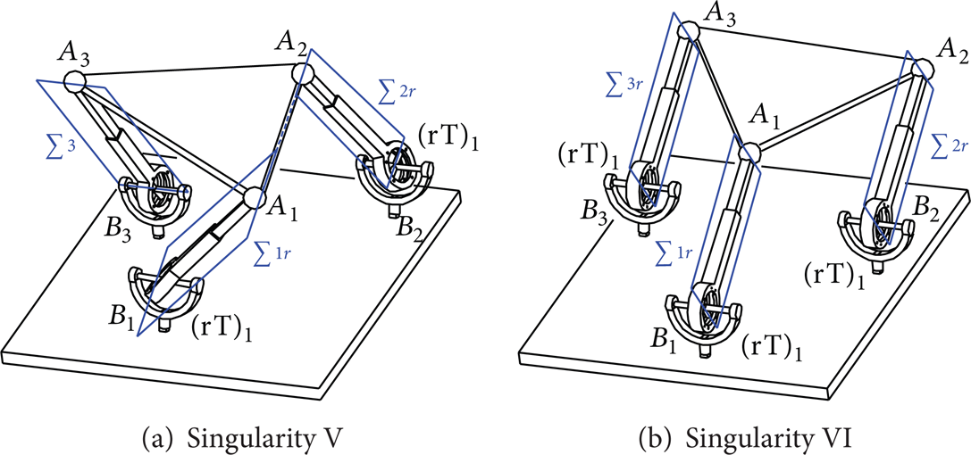
Singularity V and singularity VI.
6.4. Singularity of the 3(rT)1PS (6DOF)
When changing to the 3(rT)1PS, the singularities in the preceding analysis will all be included once the geometric conditions are satisfied. One more singularity, number VI, will occur when all the three rotational angles β1 = β2 = β3 = 0 as in Figure 12(b). In this case, the six actuation forces are distributed in three parallel limb constraint planes (∑1r, ∑2r, and ∑3r), resulting in a free rotation DOF about the direction perpendicular to the parallel planes. This is similar with singularity II and Type 5b.2 in [30].
From the above, it can be seen that when the mechanism topology changes with mobility increases, the possible singularity configurations will also increase due to the more flexible motion of the limbs. Considering the extreme limb locations for singularity I and special cases of singularity II, proper mechanism design can help avoid them. Singularity VI can also be avoided by selecting one rotation about the radial axis in one limb and other singularities need to be considered in the trajectory plan.
7. Conclusions
This paper investigated possible singularities of a class of 3rTPS metamorphic parallel mechanisms considering the geometric constraint change among the variable topologies. By changing the direction of the rotational axis of the reconfigurable Hooke (rT) joint in the rTPS limb, the limb twist system changes from order 6 to order 5 which supplies a constraint force to the platform with the direction parallel to the bracket axis and passing through the spherical joint center. Based on this, the platform constraint screw system was demonstrated to be able to change from 0 to 3, indicating that the new metamorphic parallel mechanisms have four topologies with mobility change among 1R2T, 2R2T, and 3R2T and mobility 6. Considering the kinematics solutions, geometric conditions of the mechanism design were identified and the third limb location should be inside a specific range after locating the first two limbs. Some special topologies were also listed considering special limb arrangements on the base and platform. The work was then extended to actuation scheme analysis by showing variable actuation forces. Following these, a unified Jacobian matrix was constructed by including both geometric constraint forces and actuation forces. By keeping the matrix size 6 by 6, three geometric constraint forces were changed to three actuation forces in the topology reconfiguration which gives the unified modeling to analyze possible singular configurations covering all the topologies. Six different singularities were illustrated and the general trend is that more singularities will appear with the mobility increasing due to more flexible motions in the limbs. By proper design and actuation selection, some singularities can be avoided in the mechanism configurations.
Conflict of Interests
The authors declare that there is no conflict of interests regarding the publication of this paper.