
Abstract
In recent years, since the tall buildings are getting increased and getting dense in the city area, those buildings can be more and more exposed to risks such as fire and natural disasters. In case if the high-rise building is on fire, it is not easy to put out the fire even with the modernization of the firefighting equipment. These risks can directly lead to human casualties so that it is necessary to quickly have an initial evacuation or initial suppression risks. In this paper, we propose the integrated method for reducing the fire risks through sensors such as temperature and humidity, ZigBee technology, camera control and image processing technologies, and real-time data transmission technology. Based on our proposed method, it is expected that our integrated system directly leads to the expansion of risk safety management system as well as the development of USN technologies.
1. Introduction
As the high-rise building rapidly increases, when fire breaks out, reactive action is very important and general. Also, it is seen that a number of fire alarms can be found to be with the discharged battery. This finally leads to the significant damages. Therefore, we highly need to have prewarning system and rapid response system for fire hazard. However, we can easily see aging alarms and aging fighting equipment for fire in the old buildings. In order to reduce the fire hazard, there are abundant research on checking the status of equipment, real-time data monitoring and analysis, and fire alarms and corresponding processing.
In this paper, we propose the use of the integrated system such as sensors, ZigBee technology, camera control and image processing technologies for environmental monitoring, and real-time data transmission technology between server and smart devices. By implementing these technologies, we can expect to reduce the risks due to fire. This paper is organized as follows. In Chapter 2, we briefly overview the sensors and the technologies for fire alarms. Then, we introduce our proposed system in Chapter 3. Performance evaluations are followed in Chapter 4. Finally, we conclude this paper in Chapter 5.
2. Related Technologies
In order to implement environmental monitoring for fire alarms, we need an integrated system such as sensor technologies, ZigBee-based communication, and camera control technology to obtain the status information inside the building. In this chapter, we briefly overview the USN (Sensor and ZigBee) and the image processing technologies.
2.1. Sensor Networks
2.1.1. USN
A sensor network can be defined as a network that consists of spatially distributed nodes to monitor environmental conditions. In a basic sense, sensor nodes are distributed in dense in a sensor area, and they configure the network by themselves without a coordinator in the network. Because of the characteristics such as limited battery and cost, the sensor network uses energy-dependent routing protocols.
In a sensor network, a sink node is connected to the Internet through wireless or wired medium. A user generally requests sensing information in the sensing environment to the sink node such that it gathers environmental information from the sensors distributed in a sensor network. USN sensor nodes are mainly tiny, of low-consumed power, and of low cost. However, based on the purpose, sensor nodes have different characteristics compared to the usual sensors. A sensor network uses IEEE 802.15.4/ZigBee protocol for wireless communications. Note that this standard supports low-power system and 250 kbps transmission rate at maximum. Recently, IP-USN based on IPv6 has been used [1–6].
2.1.2. ZigBee
ZigBee is based on IEEE 802.15.4 to support low-power consumption and low cost. IEEE 802.15.4 is the international standard for short-range wireless personal communications. ZigBee specifies the physical layer, MAC (medium access control), NWK (network application layers), application service layer, security, and application layer, respectively. It is emphasized here that this ZigBee is suitable for remote control, remote management, and remote monitoring so that it is widely applied to home automation, factory automation, and industrial automation. Also, Zigbee supports the mesh networks, which is suitable for sensor network. In other words, this Zigbee is suitable for complex systems. Figure 1 depicts the network layers for Zigbee [7–10].
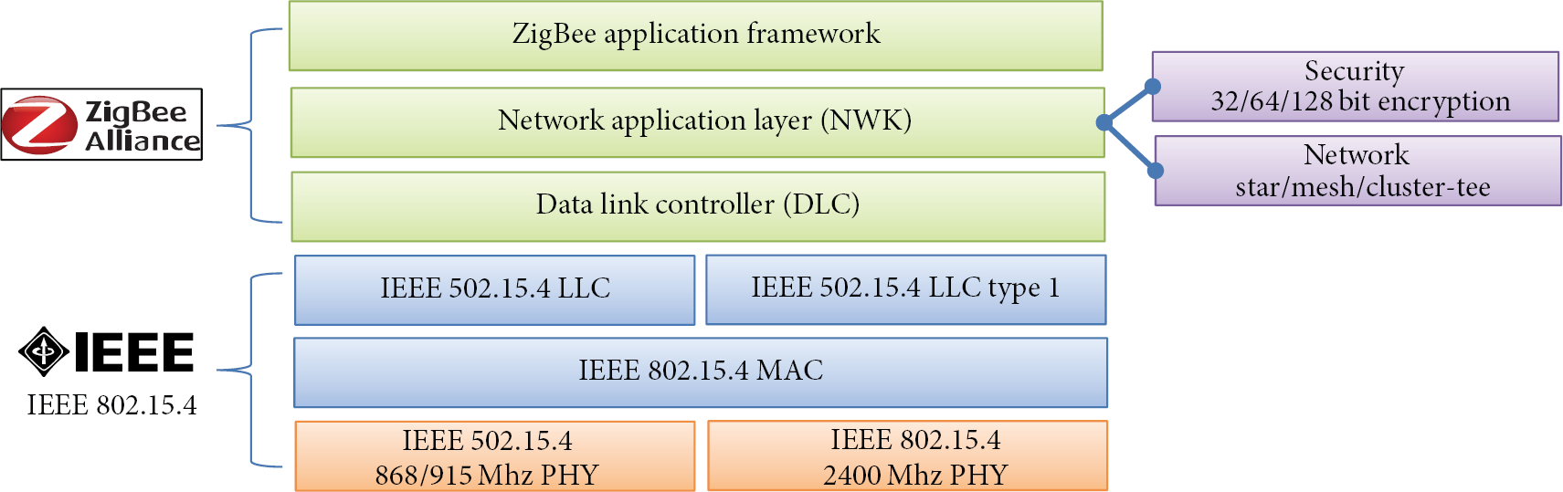
Network hierarchy for ZigBee system.
2.1.3. Sensors
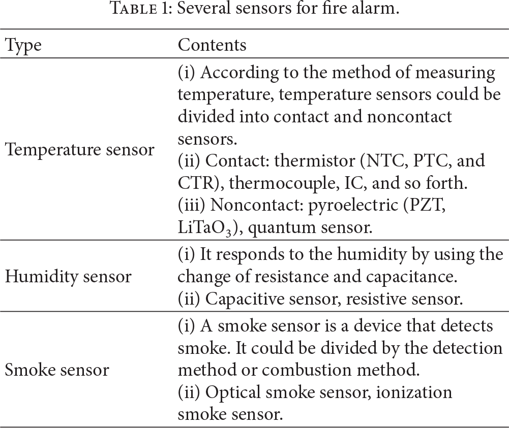
There are a number of sensors to obtain the inside environmental condition. Among them, temperature, humidity, and smoke sensors are widely used at most. The characteristics of those sensors are given in Table 1 [5, 6].
Several sensors for fire alarm.
2.2. Image Processing
2.2.1. Difference Image Method
In the difference image method for detecting the object movement, two methods are general. The first one is the method using the differences between the current frame and the previous frame. The second method is using the differences between the background image and the input frame. Under the method using the differences between two frames, if the difference between the current and previous frames is less than the threshold, it does not detect the object because there are not so many pixels changed. On the contrary, if the difference exceeds the threshold, it is regarded as an object inflow so that the object is detected [11–15].
The method using the differences between the background image and the input frame first sets the standard background image. Then it computes the differences between this standard image and the current frame. This method is shown in Figure 2.

Difference image method.
2.2.2. Block Matching Method
The block matching method is a technique for estimating the current frame from the previous frame by the unit of block under the assumption that every pixel has the same motion vector. First, the frame is divided into constant sizes of the block. Then, it can estimate the current block to be decoded based on the most similar block in the previous frame. In Figure 3, the size of the current block and the candidate block is

Block matching method.
3. Proposed Monitoring System Using USN and Image Processing Technologies
In this paper, we propose the system that can quickly detect the sign of fire by using the real-time monitoring system for environmental data and image for buildings. The proposed system can be divided into two parts. (i) The first part is related to the measurement and transmission of environmental data and (ii) the second part is related to camera control and image processing parts. In order to monitor the inside environment, ZigBee-based temperature/humidity sensor module periodically transmits the sensing data to the agent of remote servers that could be installed in the inside area or the remote area. Based on the camera setting, the camera monitors the specific area or it can be rotated by the setting time. The agent is in charge of the analysis for sensing data. If we notice the change of the temperature or humidity, we adjust the camera using panning and tilting to the area where ZigBee sensor modules are installed. We then perform the analysis for the still images or movies. Before performing the data analysis, the agent transmits the sensing data and video images to the remote server or the smart devices of administrator. Figure 4 shows the overall structure for our proposed system.
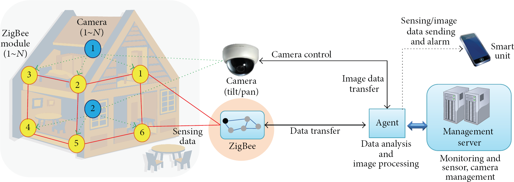
Overview of the proposed system.
The agent as shown in Figure 4 can perform data analysis from each ZigBee module and also perform image processing. Furthermore, the agent transmits the data and video image to management server and smart unit as well as controlling remote cameras. For example, if the sensing data from ZigBee module 2 exceeds the threshold, it uses panning and tilting of camera, and then it can obtain the video images for the area of ZigBee module 2. Based on these video images, it performs the image analysis for finding the fire risks. At the same time, the agent sends both the warning message and sensing data values to the management server and smart unit.
3.1. ZigBee-Based Sensor Module
ZigBee-based sensor module mainly performs gathering the environmental information such as temperature and humidity in the building and also performs transmitting the data gathered to the other ZigBee module or outside through the wireless network. Sensor modules could be installed inside or even outside. Note that the installation type could be determined according to the environment. Figure 5 depicts the block diagram for ZigBee-based sensor module.

Block diagram for ZigBee-based sensor module.
Sensor module mainly consists of several parts for power management, environment sensors (temperature and humidity), and transmission for sensing data through RF communication of ZigBee, receiving the control command from the agent and the control part for flow control.
3.2. Protocols for RF and Wireless Network
In the proposed system, we use RF communication between ZigBee-based sensor modules, while a wireless network is used to transmit or receive data and command between the agent and the sensor module. For these two types of communication, it is necessary to define basic protocol format to easily handle data and control command as depicted in Table 2.
Protocols for RF communication and wireless network.

Information of the packet is as follows.
STX: start of text(Start 0x02)l.
Length: the data length for Command 1 to checksum.
Command 1: sender unit.
→ A: agent.
→ B: ZigBee sensor module.
→ T: temp. area.
Command 2: receive unit (same as Command 1's text).
Command 3: T → request, R → response.
Command 4: function.
S_ID: sender ID.
R_ID: receiver ID.
Data: sensing data and command data field.
Status: RF channel (0~127) and battery check fields.
Checksum: error checking.
ETX: end of text (End 0x03).
The protocol between camera and agent is exactly the same as the protocol shown in Table 2. In Command 4 field, “S” is for sensor's position number, “R” is for right movement, “L” is for left movement, “U” is for camera up, and “D” is for camera down. Here, we use C_ID field for camera control and distinction, while S_ID field and R_ID field are not used.
Note that we use the wireless network between the camera and the agent, while the other network is used to make a connection to ZigBee-based sensor module. For the camera, it can support wired and wireless communications. Also, the camera uses TCP/IP protocol such that it can use tilt/pan functions as well as zoom in/out functions.
3.3. Data Analysis and Data Processing at Agent
In our proposed system, the agent performs saving and analyzing the sensing data and video data as well as data transmissions. Also, it analyzes the video data obtained by camera control and transmits the analysis results to the management server and smart devices. Figure 6 shows the process for analyzing and transmitting sensing data and video data to the server (or smart unit).
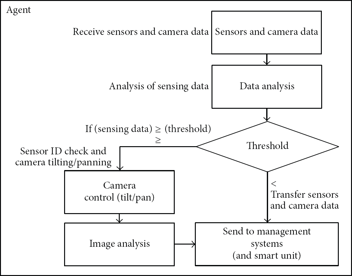
Data analysis process at the agent in the proposed system.
The data from ZigBee-based sensor module and cameras does not directly transmit the management server. This data is transmitted to the agent first, and then the agent performs the data analysis process for transmitting its analytical data to the final destination. If the sensing data does not have any problem, the camera takes a video for the fixed time at the fixed position. However, in order to update the background image for image processing, it traverses the position of ZigBee-based sensor module and updates the background image of each position. As shown in Figure 6, if sensing data is closed to the threshold, we use the tilting and panning functions of the camera and analyze the video image at the agent. The reason we perform the video analysis is to provide the method that can help the administrator notice the current status. Also, the video analysis can distinguish whether the changes are from the general environmental changes or catching fire so that it is very necessary to distinguish the current changes.
3.4. Camera Image Feature Information Analysis
During the image processing analysis at the agent, background replacement technique compares background image with its histogram to detect the occurrence of fire. However, if the background image changes due to the change of light or environmental change, it is not easy to detect the target object, because the changes could be regarded as a noise.
Therefore, we compare the background image with input image by the unit of the block. When the difference is less than the threshold, it is regarded as changes of some pixels. We then update the background image by replacing the block in the background image with the block of the input image. If the difference exceeds the threshold, these belong to the cases of the fire or other factors so that we perform histogram analysis. Then, the analytical results are transmitted to the management server (or smart units). Figure 7 shows the process of image feature information analysis.
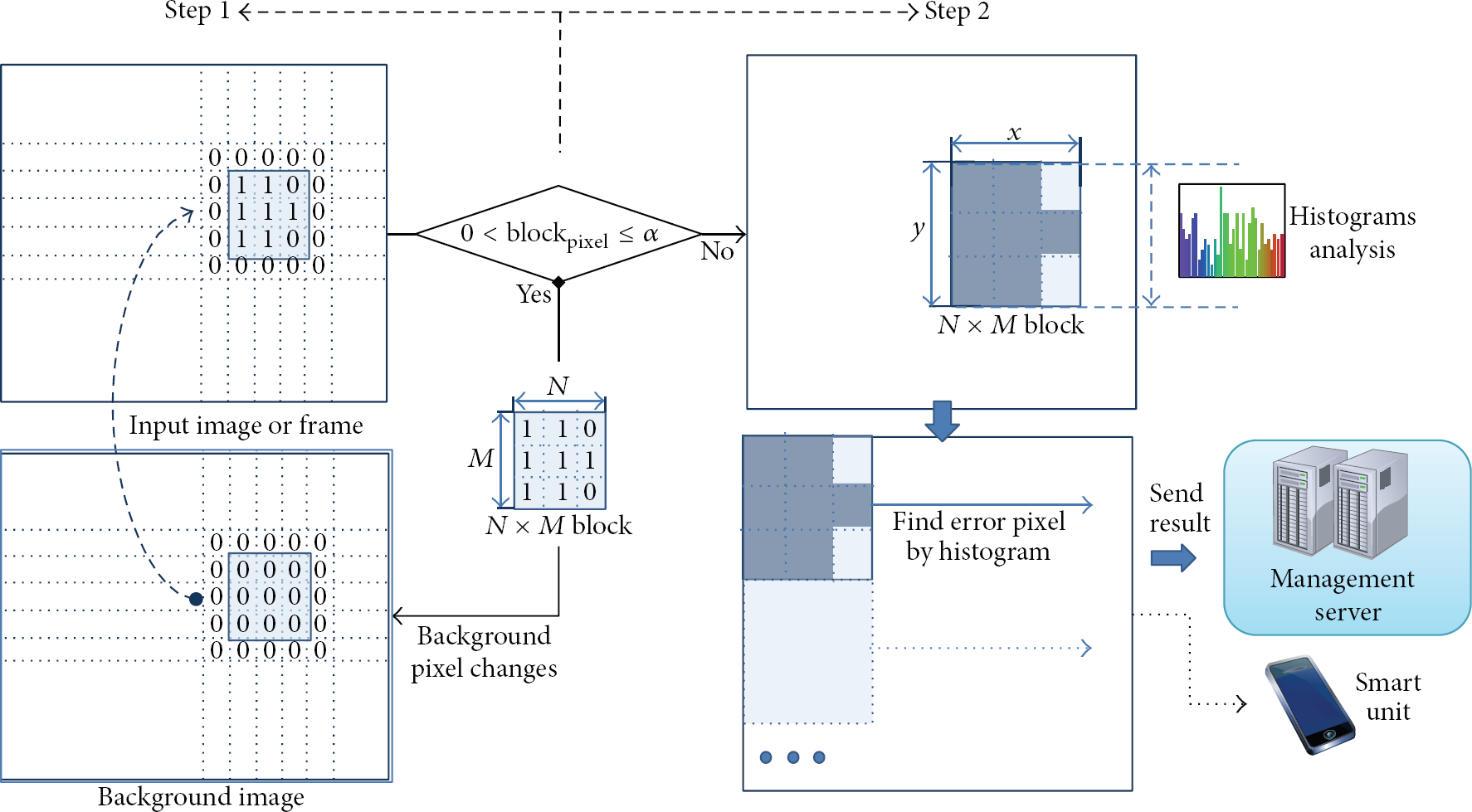
Process for analyzing video feature information.
4. Performance Evaluation
In this chapter, in order to evaluate our proposed system, we measure the temperature and humidity of ZigBee-based sensor module and the performance of image analysis. First, we put 4 sensor modules to the different positions (each position on one side of the rectangle). Then, we check whether the sensing data from 4 sensor modules is correctly transmitted to the agent by comparing the sensing values of 4 sensor modules with the received data at the agent through the wireless network.
We compare the temperature and the humidity at each sensor module with the saved values of the agent. The comparison result is that the real measurement values ((inside) T, (inside) H) are exactly the same as the saved value of the agent ((agent) T, (agent) H) without any error as shown in Figure 8.

The comparison between the measurement values at each sensor module and the saved values at the smart device.
Figure 9 depicts the results when we change the temperature and humidity to the environment of fire for 5 times. With this experiment, we can evaluate the performance of our video analysis. We continuously check whether there is an error during our video analysis process.

The results when temperature/humidity is changed to each warning level.
We define the warning level when the temperature and humidity are in the range of 45°C~55°C/10%~20%. In a similar manner, we define the danger level when the temperature is over 56°C and the humidity is lower than 10%. Figure 9 shows the results of performing the video analysis when we intentionally make a situation according to each level. At every point, we can obtain the same level results according to the temperature and humidity warning level for every point.
5. Conclusions
In this paper, we proposed the method of gathering environmental information such as temperature and humidity by using the sensors of fire alarms and transmitting this information to the management server to reduce the possibility of the fire risks. Here, we also proposed the use of camera image to monitor the inside status as well as reducing the false alarm due to the fault operation of sensors. Our experiment results show that the integrated technologies such as gathering data through ZigBee-based sensor modules, camera control, and video analysis can maximize the effects of our system. With the combination of the outstanding technologies, we can improve the applicable areas of USN.
Footnotes
Conflict of Interests
The authors declare that there is no conflict of interests regarding the publication of this paper.