
Abstract
Recently, energy saving is one of the important issues for polymer processing industry. Electromagnetic induction heating has many advantages such as fast heating and low energy consumption. Previous studies using electromagnetic induction heating for rapid tool heating have indicated that the temperature uniformity on a cavity surface is not easy to be achieved. In this paper, two different coils were used for heating uniform 7 mm thick hot work tool steel (JIS SKD61) surface. One is a four-row coil with opposite current directions and the other is a two-row coil with identical current directions. Magnetic flux concentrators were used to control magnetic field and heat the workpiece uniformly. The heating experiment results showed that coil with opposite adjacent current directions had more uniform temperature distribution on tool surface. The temperature uniformity was about 94%∼95%. The coil with identical adjacent current directions had higher average temperature and the temperature rose from 50°C to 150°C in 15 seconds.
1. Introduction
Induction heating is a common heating technique applied in industry. For example, it can be applied for metal welding, heat treatments, annealing, and so forth.
In plastic industry, induction heating was applied to injection molding. High tool temperature can improve replicability of microinjection molding [1]. But induction heated tool surface temperature uniformity is difficult to be achieved. By applying different induction coils and an integrated power supply, Fujita et al. [2] showed that the induction heating temperature on different zones could be controlled. In 2006, Yao et al. [3] increased tool temperature by proximity effect which means that currents of opposite directions flow to two different metals and cause the current aggregate on the proximity surface. With the proximity effect, tool temperature can be heated to 240°C in 5 sec. In 2006, Chen et al. [4] applied induction heating to injection molding. The mold temperature could be heated to 100°C∼140°C from 60°C in 3 sec. Their results showed that a higher mold temperature can increase microstructure transcription. The above papers also showed that the uniform temperature is very important to heating mold. In this paper the coil design and temperature distribution were the main concern. There are several techniques to modify the magnetic field distribution and uniform heating distribution along the heating length such as reducing the number of turns in the center or turns density [5], adjusting the distance between working coil and workpiece [6], modifying the cross-section shape of working coil [7], or using multilayers of working coils [8]. Uniform heating coil could not heat the workpiece uniformly, so that the coil design must consider several conditions, such as current direction, distance between coil and workpiece, and turns of coil.
The induction heating principle is similar to that of a transformer. Figure 1 shows the schematic of a simple transformer model. The induction coil is the primary side and the workpiece is the secondary side. Alternating current flows in the primary and produces an alternating magnetic field. The secondary side will be inducted and the workpiece will also encounter an inducted alternating magnetic field. According to Faraday's Law, the alternating magnetic field on the secondary side will have inducted current, called eddy current. The eddy current will flow through the workpiece and the workpiece will be heated by resistance.
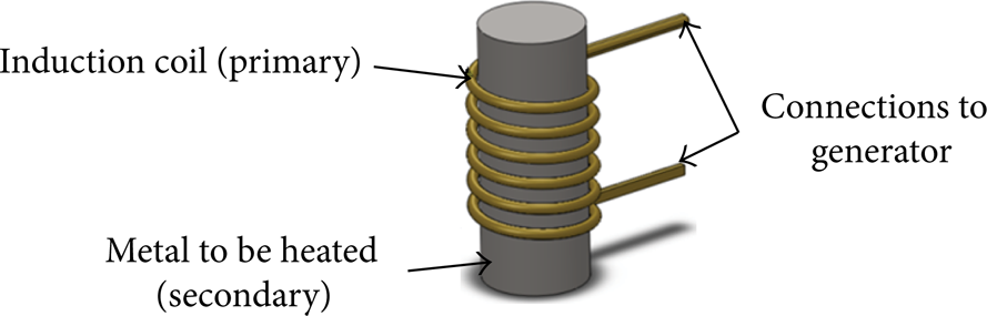
Schematic of induction heating.
2. Experiment of Induction Heating
Previous studies showed that induction heating could heat the workpiece quickly, but temperature uniformity was still a problem for heating a planar workpiece. In the present study, two experiment induction heating coils were designed with different magnetic flux concentrators’ settings. Magnetic flux concentrators can guide magnetic field forward to the planar workpiece. The aim of the experiments was to find the effects of coil designs on heating results with different settings of current directions and magnetic flux concentrators in each coil. Heating power and distance between coil and workpiece were also considered.
The experiment apparatuses used in the present study were a max 30 kW high frequency power generator, a transducer, and a cooling water supply machine. The high frequency power generator operation provided current output with frequency ranging from 50 to 100 KHz. The cooling water supply machine provided cooling water to lower the temperature of the induction heating coil.
2.1. Experiment Steps
Apply coating on planar workpiece surface so the emissivity of the workpiece surface was close to 0.94. The material of workpiece is SKD61 and the dimensions were 230 mm long, 150 mm wide, and 7 mm thick. Fix the workpiece 5 mm in front of the induction heating coil as shown in Figure 2.
Heat the workpiece to 50°C as the initial temperature then proceed to heat the workpiece further.
The workpiece was heated for 8 seconds; then the power was turned off for 7 seconds so total period of the experiment was 15 seconds. Record the heating images of opposite heating surface of workpiece at 0, 5, 8, 11, and 15 seconds by infrared ray imaging.
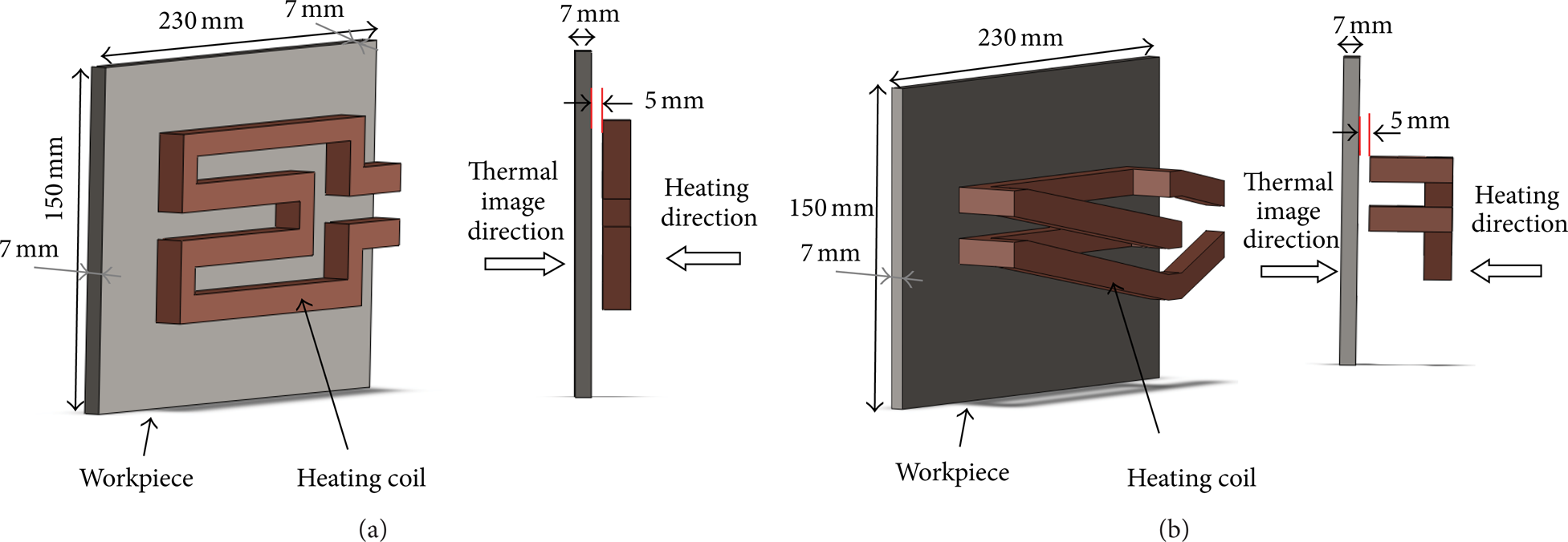
The setting position between workpiece and coil.
Following the experiment steps, two coils, two-row and four-row, were used for the experiments as shown in Figure 4. Different adjacent current direction and power parameters were considered in this experiment.
Furthermore, magnetic flux concentrators were applied in the experiment. The experiment parameters of the setup were shown in Table 1.
Experiment parameters setup.
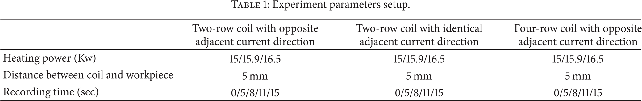
Figure 3 showed the experiment heating coils. The experiments were processed with two-row and four-row coils for the induction heating tests with different current directions. The cross-section of each coil is square, dimension is 12 mm × 12 mm, and the pitch between each coil is 12 mm.

Coils used in the experiments. (a) Four-row coil with opposite adjacent current direction. (b) Two-row coil with identical adjacent current direction.
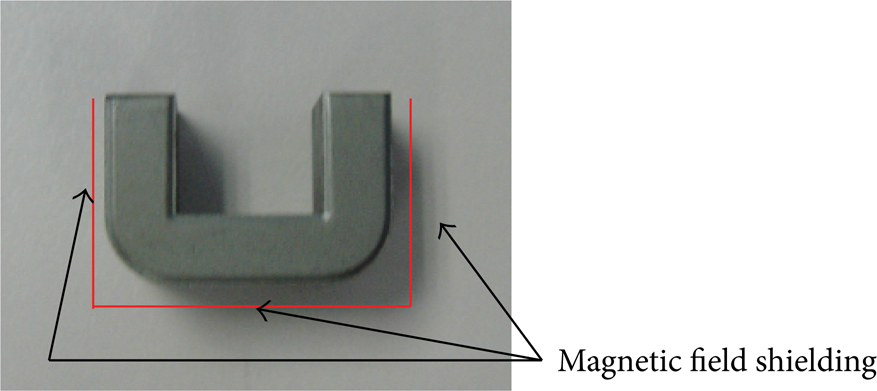
Magnetic field concentrator.
The coil applied concentrators (Figure 4) for increasing intensity of magnetic field in some areas. Figure 5 shows the comparison of induction current distribution of coils with or without magnetic flux concentrators. Concentrators also could be used for controlling the magnetic field and change the heating areas. Some of magnetic flux concentrators were set up to be opposite in the direction to that of the heating workpiece to control heating area. Figure 6 showed (a) a two-row coil with opposite adjacent currents, (b) a four-row coil with opposite adjacent currents, and (c) a two-row coil with identical current.
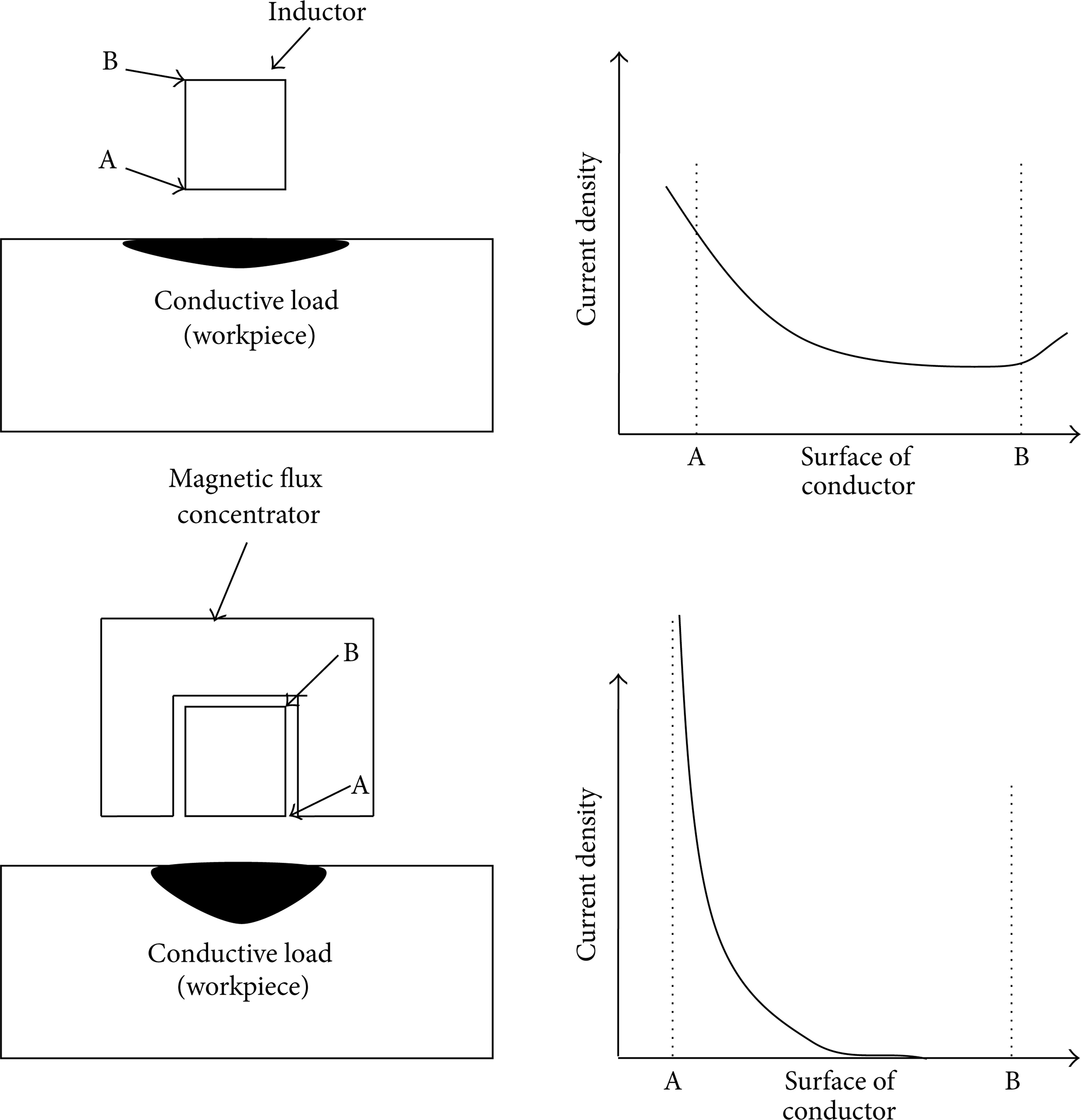
The comparison of induction current distribution of coils with or without magnetic flux concentrators [9].

Experiment heating coils. (a) Two-row coil with opposite adjacent currents directions. (b) Four-row coil with opposite adjacent currents directions. (c) Two-row coil with identical adjacent currents directions.
3. Experiment Results
The heating power was set to 15 kW for the heating experiment. Figures 7, 8, and 9 showed the temperature distribution comparison on the workpiece between coils with or without magnetic flux concentrators. Each figure from the top was recorded at 0, 5, 8, 11, and 15 seconds. Test results with magnetic flux concentrators were shown on the left hand side, while test results without magnetic flux concentrators were shown on the right hand side.

Temperature distribution of two-row with coil opposite adjacent current direction. (a) With magnetic flux concentrators. (b) Without magnetic flux concentrator.

Temperature distribution of two-row coil with identical adjacent current coil. (a) With magnetic flux concentrators direction. (b) Without magnetic flux concentrator.

Temperature distribution of four-row coil with opposition current coil. (a) With magnetic flux concentrators direction. (b) Without magnetic flux concentrator.
According to the experiment results, magnetic flux concentrators had high influence on induction heating results. In the 1∼8-second heating test, the workpiece showed higher temperatures with magnetic flux concentrators. In Figure 8, at the eighth second, results showed that the first and fourth rows’ heating efficiencies were higher than those of the second and third rows. From Figure 9 one could find that magnetic flux concentrators could not completely isolate the electrical magnetic effects between proximity coils. Compared to Figures 7 and 8, one could observe that the heating test with identical adjacent current directions had higher heating efficiency than that of the opposite adjacent current directions. In Figure 6, the white part indicated that the temperature was over 200°C. This temperature was not reached in the test for a coil with opposite adjacent current directions.
3.1. Temperature Uniformity Analysis
The temperature data obtained from thermal image were used to calculate average temperature and standard deviation. The standard deviation is defined in
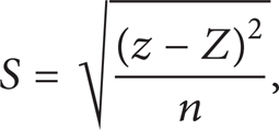
where S is standard deviation, z is temperature, Z is average temperature, and n is total number of data.
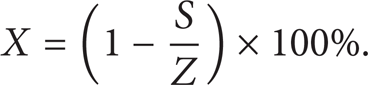
Temperature uniformity (X) was calculated by averaging the value and standard deviation. The equation is shown as follows:
3.2. Temperature Analysis of the Two-Row Heating Coil
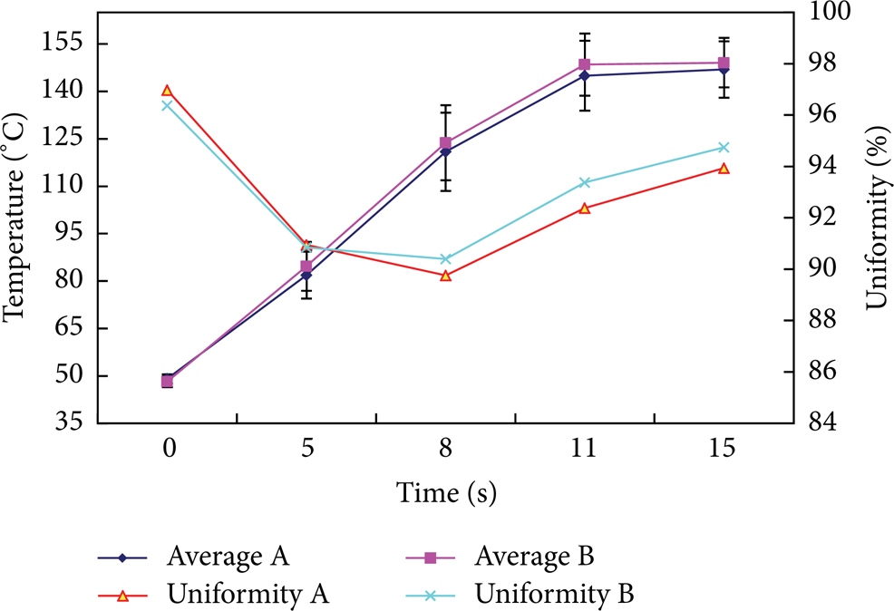
Figure 10 showed the measurement area heated by two-row coil with identical and opposite adjacent current directions. The heating area was 64 mm long and 36 mm wide. There were 2600 temperature data points in the measurement area. After calculation, the average temperature, standard deviation, and temperature uniformity at 0, 5, 8, 11, and 15 seconds were found and were shown in Table 2. Figure 11 showed the comparison between identical current directions and opposite current directions after 15 seconds of heating. In Figure 11 line A was the average temperature heated by the coil with the identical current directions and line B was the average temperature heated by coil with the opposite adjacent current directions. Check the results in Figure 11 and find that the identical adjacent current directions had a higher heating rate, while the opposite current directions had better temperature uniformity.
The experiment results of temperature distribution of the plate heated by the two-row heating coil.

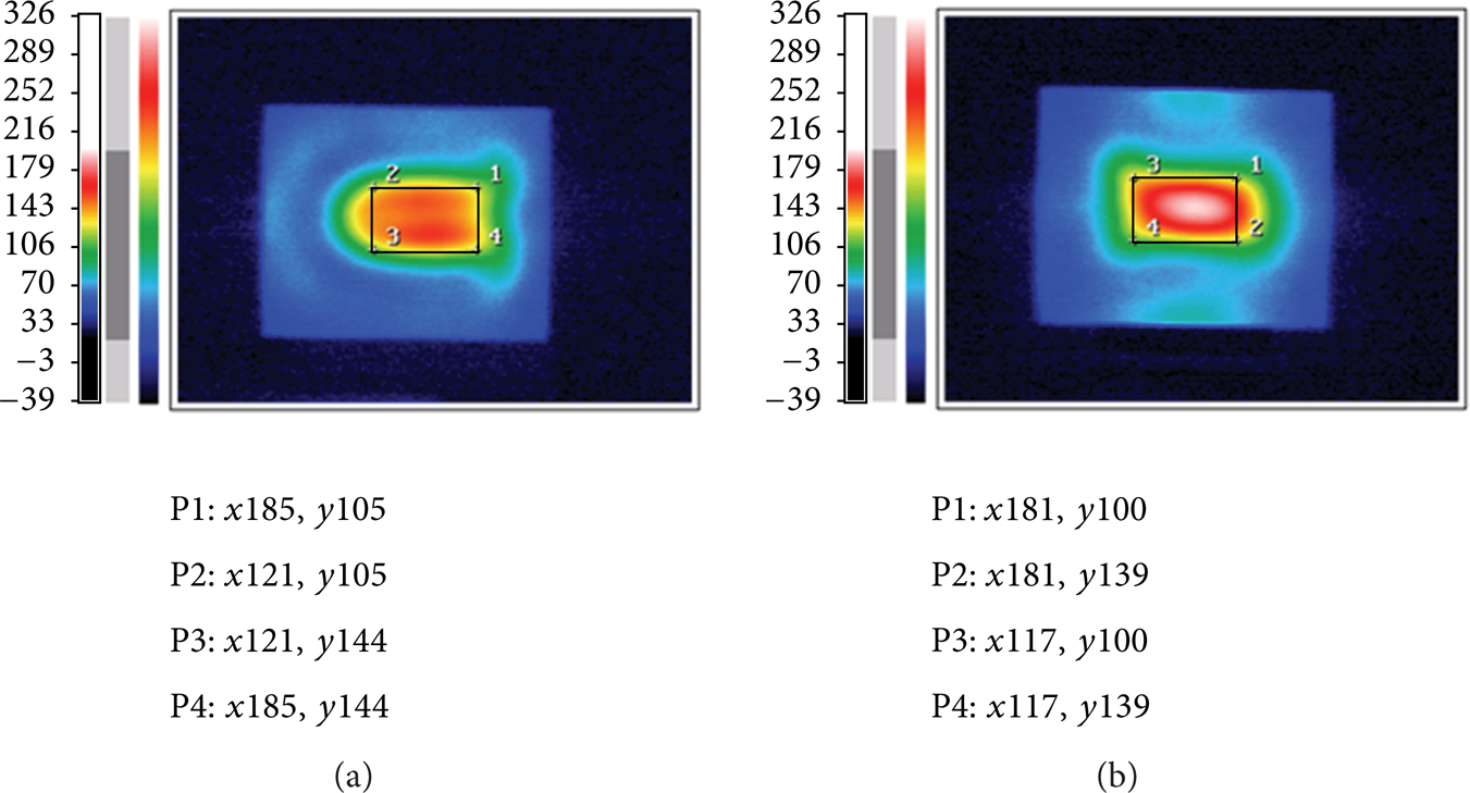
Measurement area of two-row heating. (a) Opposite adjacent current directions. (b) Identical adjacent current directions.

Comparison of heating results for coils with identical and opposite adjacent current directions.
3.3. Temperature Analysis of Four-Row Heating
The heating power was set to be the same as that for the two-row experiments. The measurement area was 63 mm long and 74 mm wide with 4800 temperature data points.
Figure 12 showed the measurement area. Table 3 illustrated the average temperature, standard deviation, and temperature uniformity at 0, 5, 8, 11, and 15 seconds. Figure 13 showed the comparison between two- and four-row heating. Lines A and B were the heating results with the four-row coil and two-row coil with opposite adjacent current directions. The results of Figure 13 showed that the temperature uniformity and average temperature of the four-row heating coil did not show any apparent difference from the two-row heating cases.
Experiment results of two-row heating.


Measurement area of four-row heating.
Comparison between the two- and four-row heating cases. For both cases, the adjacent currents were in opposite direction.
From the results shown above, the direction of current appeared to have significant influence on average temperature and temperature uniformity.
3.4. Temperature Analysis for Different Heating Power Levels
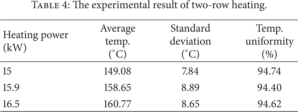
The next heating test was conducted with varied levels of heating power. The average temperature was shown in Tables 4 and 5. Table 4 showed the two-row heating with opposite adjacent current directions, while Table 5 showed the four-row heating with opposite adjacent current directions. Figures 13 and 14, respectively, showed the comparison between different power levels of two- and four-row heating. Figures 14 and 15 demonstrated that the temperature uniformity was not significantly affected by varied heating power and the average temperature was increased due to an increase in heating power.
The experimental result of two-row heating.
The experimental result of four-row heating.

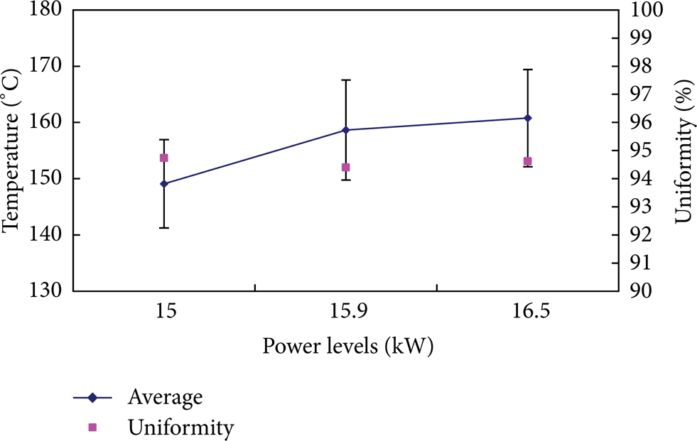
Comparison of different heating power levels in two-row heating.

Comparison of different heating power levels in four-row heating.
4. Conclusions
From the results of the present investigation, one could draw the following conclusions.
Identical direction current in the proximity coil had better heating rates. The case of opposite adjacent current directions had better temperature uniformities.
During induction heating, the variation of the average temperature and uniformity was in good agreement with the two- and four-row coils with opposite adjacent current direction.
Heating power had no significant effects on temperature uniformity. The average temperature was increased due to an increase in heating power.
During the 8-second induction heating period, the temperature uniformity was reduced gradually. During the next 7 seconds of heat transfer, the temperature uniformity was increased gradually.
The main finding of this work was that opposition current with magnetic flux concentrator heating had a better uniform heating result. This finding is of great practical importance for the design of tool cavity heating.
Conflict of Interests
The authors declare that there is no conflict of interests regarding the publication of this paper.