
Abstract
This paper presents the development of a robotic solution for a problem of fast manipulation and handling of onions or artichokes in the food industry. The complete solution consists of a parallel robotic manipulatior, a specially designed end-effector based on a customized vacuum suction cup, and a computer vision software developed for pick and place operations. First, the selection and design process of the proposed robotic solution to fit with the initial requeriments is presented, including the customized vacuum suction cup. Then, the kinematic analysis of the parallel manipulator needed to develop the robot control system is reviewed. Moreover, computer vision application is presented inthe paper. Hardware details of the implementation of the building prototype are also shown. Finally, conclusions and future work show the current status of the project.
1. Introduction
According to a recent report [1], the food and drink industry is the largest manufacturing sector in the EU in terms of turnover, value added, and employment. Moreover, the food and drink industry sector can be splitted into the following subsectors: meat products; various food products; drinks; dairy products; bakery and farinaceous products; animal feed; processed fruit and vegetables; oils and fats; grain mill products and starch products; and fish products. The meat sector is the largest subsector, representing 20% of total turnover and the processed fruit and vegetables represent the 4% of total turnover. The robotic solution presented in this paper could be classified as a technological innovation for the processed fruit and vegetables subsector. In short, the application target is the fast manipulation of onions or artichokes during the feeding of cleaning and cutting machines (Figure 1).

Manual manipulation of onions during the feeding of cleaning and cutting machines.
Robots seem to be a promising solution to manipulate fresh fruit and vegetables due to their accuracy, high repeatability, speed, and so forth. However, for working on the food industry, they have to achieve some special requirements, such as high speed activation, adaptation to a variety of shapes, maximum adherence and minimal pressure, no damage to the product, low maintenance, high reliability, low weight, being approved for contact with foodstuffs, low energy consumption, requiring positional precision for both gripping and releasing of the product, ease of cleaning, and easy and fast ejection of the product. Robotics for food industry and agricultural applications are having a great impact and a great growth is expected in the coming years [2]. There are several examples of robotic solutions developed for different application areas, as picking [3, 4], machine vision [5], or milking process [6]. Nevertheless, less attention has been put on the manipulation of vegetables or fruits, due to the problem of damaging the tissues of the vegetable.
Vacuum suction cups have the capability of gripping and placing and produce low bruising, tearing, breaking, and deformation in the manipulation and handling of horticulture products. Suction cups have traditionally been used for manipulation and handling objects in the food industry. Nowadays, more and more innovations and advanced systems have been developed by industry and academia. For instance, FIPA GmbH develops vacuum cups customized to meet the needs of each foodstuff from eggs to pralines. Another example of advanced suction systems is the suction cups for mandarins manufactured by Serfruit company. Robots manufacturers, such as ABB, Adept, Kuka, and Fanuc, have their own commercial solution to manipulate and handle objects in food industry. Different kinds of robot grippers, most of them based on suction cups, have been developed by robotic manufacturer to each application in food industry. However, food manipulation is currently a wide area for developing new devices that are able to help human with some cumbersome tasks.
The goal of this paper is to present a robotic solution which deals with the manipulation of onion or artichokes during the feeding of cleaning and cutting machines. The vegetables are in a hopper and the worker has to take them and place them on a transfer line for the machine. The current bottleneck of the whole system is the capacity of workers to feed the machine, as the present ones are able to manage near 100 units per minute. The goal of this work was to find a robotic solution able to be integrated on the current machines with the following features:
workspace: 620 mm on X axis (to be able to enter the hopper),
pick and place frequency: 80–120 cycles per min,
maximum weight of the onion/artichoke: 1 kg,
4 or 5 degrees of freedom: 3 for positioning and one or two more for orientating the vegetable.
This paper is structured as follows. Section 2 shows the selection and design of the robotics solution proposed. Section 3 centers on the kinematic and workspace analysis of the parallel manipulator. Then, the developed computer vision system is described in Section 4. Section 5 shows the hardware details of the implementation of the building prototype and it shows the first results. Finally, conclusions and future work section shows the current status of the project.
2. Design and Development of the Robotic Solution
This section shows the design stage of the solution. First, the stage of evaluation of different options is resumed, and then design of the robotic solution using CAD tools and the design of vacuum suction cup are presented and commented.
2.1. Evaluation of Different Options
Previously to the viability study, commercial options were evaluated. Both serial and parallel kinematic architectures for robotic arms were considered. Some of the options of this study are summarized in Tables 1 and 2. Table 1 is for serial robots and Table 2 is for parallel ones. These tables show that, for the case of serial robots, SCARA configuration is the nearest solution to the requirements, but there is not any commercial solution that really fits the needed requirements. In general, there is not any serial robot faster than 35 cycles per min. If we decide to use serial robots, four units of a SCARA robot will be needed to get 120 cycles per min.
Commercial serial robotic solutions evaluated for manipulation.

1: Motoman SCARA HM-10-600; 2: Motoman SCARA YS650; 3: Adept SCARA Cobra s600; 4: Mitsubishi SCARA RH-6SH; 5: Mitsubishi RP-5AH.
Commercial parallel robotic solutions evaluated for manipulation.

1: ABB irb340; 2: ABB irb340S; 3: ABB irb360; 4: Adept S650H.
In recent years the number of applications of parallel robots has increased [7–9]. Moreover, one of the most extended applications is in packaging for food industry due to the high velocities and acceleration achieved by these robotic devices. However, commercial units are normally very heavy and they have workspaces wider than needed. This provokes that the dimensions are greater than needed and the integration of the unit in an agricultural machine turns into a difficult task.
2.2. Proposed Robotic Solution
A new designed robot arm was decided to be built for the solution of the problem. The chosen kinematic architecture was a delta architecture [10]. To evaluate the viability of the proposed solution, different simulations have been carried out to test a priori different robotic solutions based on delta architecture (Figure 2). The simulations were made with a payload of 0.5 kg on the end-effector and with the motors localised on the upper platform of the robot. The horizontal workspace of this robot is 800 mm (± 400 mm) and the simulation was obtained with a cycle velocity of 60 cycles per min. This implies that we will get the requirements using two units of the designed solution.

Model and numerical simulations made with ADAMS© for selection of the device actuators.
The bottom part of Figure 2 shows the required torques for the actuators in a typical trajectory. It shows that quite small actuators (less than 2 Nm) can be used to fit the continuous torque requirements. This allows us to use small brushless motors and a low reduction coupling system. Peak torque requirements can be up to 10 Nm when starting from rest position (simulations were done without path planning).
Figure 3 shows an illustration of the proposed solution, once integrated on the agricultural machine. As it can be seen, two units are hanged on the hopper and work together to achieve the 120 cycles. As the figure illustrated, the robot is able to pick the vegetable and place it on a transfer line without collision with the hopper or the second unit of the robot.

Proposed robotic solution: concept.
2.3. Design Using CAD Tools
The design of the robotic solution has been carried out using Autodesk Inventor. Autodesk Inventor is a 3D CAD software that offers an easy-to-use set of tools for 3D mechanical design, documentation, and product simulation. The robot is composed of two platforms (Figure 4), one fixed platform on the upper part and one moving platform on the lower part, and of three closed kinematic chains forming 120°. Each kinematic chain is composed of two links and four passive spherical joints. The combination of the constrained motion of the three arms connecting the fixed platform to the moving platform ensures 3 resulting translational degrees of freedom (DOF). Moreover, an additional central arm has been designed to transmit 1 DOF to the robot end-effector, using these additional orientation capabilities to leave the onion or artichoke over the transfer line (Figure 4). Actuators are located over the upper platform and they move the moving platform through the combination movements of the three legs. The fixed position of the actuators allows a low inertia and high velocities on the end-effector.

Description of the final design robotic solution over a CAD image.
2.4. Design of Vacuum Suction Cup
The selection of the right manipulation strategy is of paramount importance for the definition of the best approach to handle a soft object, such as vegetables and fruit. In our case, the selected manipulation strategy is based on air using a suction cup. The object is manipulated and handled using the suction created by a negative fluid pressure of air [11].
In our application for manipulating and handling onions and artichokes, a customized suction cup has been designed to be capable of adapting itself optimally to the surface of the onions and artichokes and built using a particularly soft material, such as silicon (Figure 5). The main feature of the designed cup is the flexible side concavities that allow the adaptation of the cup to the morphology of the vegetables plugging the holes to achieve enough creation of the vacuum. The initial version lacked reinforcements between the concavities that give rigidity and prevent, at times the side walls of the cup bend upwards, colliding with other vegetables.

Views of the designed vacuum suction cup.
3. Kinematic Analysis and Workspace
3.1. Kinematic Analysis
Next, the kinematic analysis of the delta robot is reviewed, and the needed equations for the control of the system are written [12]. The used geometrical model is the one shown in Figure 6. The global reference system ∑(X, Y, Z) is located at the center of the upper (fixed) platform, with the z-axis perpendicular and pointing downwards and the x-axis perpendicular to the axis of the actuator 1. A second reference system ∑eff(Xeff, Yeff, Zeff) is located at the center of the moving platform (lower) and it represents the current position of the end-effector of the robot related to the system.

Geometrical model of the robot.
Due to the symmetry of the robot, each kinematic chain bar and forearm could be treated separately. Lengths of the arm and forearm are L a and L b , respectively. Each arm has a reference system ∑ i (X if , Y i , Z i ) located at a distance R of the global reference system ∑, and it has been rotated an angle θ i (0°, 120°, and 240°) (i = 1, 2, 3 legs).
Joints at ∑
i
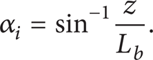
system are active and the joint positions are represented by α
i
. Joints at points
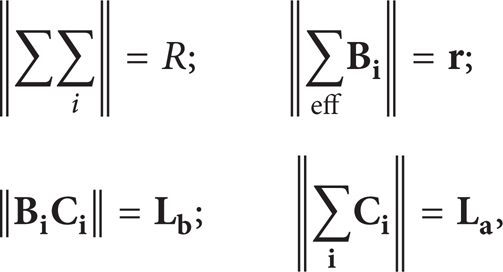
where
Equation (1) can be expressed as

where Δr = R − r and
If forearms are considered rigid bodies, constraint equations for the robot are given by
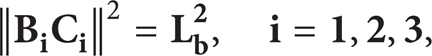
which can be expressed as

with

Expression (4) is the equation of sphere with

The point
3.2. Inverse Kinematic Analysis
In this subsection, the inverse kinematics problem is briefly recalled as theoretical background. As it was commented in the kinematic analysis subsection, the proposed robotic device is symmetric; therefore only one arm and forearm will be considered (Figure 6). The inverse kinematics problem results from the determination of angle values α
i
(i = 1, 2, 3) for a desired end-effector pose
In our case, as it can be observed in (7), two solutions are possible for two possible position solutions for each link. Moreover, only one of the two solutions can be reached by the manipulator (see Figure 7). This result allows us to conclude that eight possible solutions can be computed for a desired final effector pose using the inverse kinematic model [13]. To avoid singularities and assure a practical configuration, the selection of each joint pose should be made taking into account the following geometrical constraints: if x − R ≥ 0 then α
i
can be computed using (7) and if x − R < 0 then

Graphical representation of inverse kinematic solutions.
3.3. Direct Kinematic Analysis
Direct kinematics of a parallel manipulator determines end-effector pose

Graphical representation of direct kinematic solutions (3 spheres): two spheres intersect in a circle and a third sphere intersects the circle at two points.
3.4. Workspace
In the following lines, the theoretical workspace of the proposed parallel robot is presented and commented in detail. In any robot design stage, it is very important to study and analyse its reachable workspace to know if the designed robot fulfills the workspace requirements of the target application [14]. The computation of the boundary of robot workspace has been computed through solving the inverse kinematics as it can be called theoretical workspace. Figure 9 shows the wide robotic workspace and the maximum vertical and horizontal displacement achieved with the current dimensions of the robot that is 410 mm and 380 mm, respectively. However, the robot workspace is usually constrained by singularities, position, and type of drives, link, and platform collisions. Taking into account these constraints, real reachable workspace of the robot, which fulfills the initial requirement of 620 mm on X axis at least, is shown in Figure 10. The information extracted from the reachable workspace has been used to modify the dimensional design if it is needed and to locate the designed robotic device in the work environment (Figure 10).

Workspace of the designed parallel manipulator: orthogonal and top view.

Reachable workspace of the designed parallel manipulator: 2 units (red and green volumes).
4. Computer Vision System
In automatic picking and place tasks, robots require the help of a computer vision system to recognise object shape and orientation and to track the conveyor in order to allow manipulation during object motion on the conveyor track. Moreover, computer vision can provide more information to classify every product.
In our case, the output of the computer vision system is the computation of X, Y position of the onion and estimation of its Z coordinate (depth). The developed computer vision algorithms are based on basic morphology operations: erosion, dilation, and disconnection. After that, a blob detection was implemented and the computation of the area of each blob is done. With this information, the best candidates of onion to be picked are selected and the X, Y coordinates of their centre of mass are computed. Then, their Z coordinate is computed using prior knowledge learned from a training set (Figure 11).

Snapshot of the implemented computer vision system.
We are using at the same time a well-known low-cost depth camera, Kinect, to compare the estimated depth with the depth computed by drivers provided by the manufacturer. In this case, a factory's calibrated settings are used to compute the 3D points from the disparity measurements. A most sophisticated calibration of Kinect can be carried out using the Kinect calibration toolbox from [15]. However, a standard deviation error of 5 mm in the worst case is assumable for us taking into account our target application.
5. Experimental Results
A prototype was built to test the performance of the proposed robotic solution in a realistic scenario. The prototype was composed of the following components (Figure 12).
Low-cost control multiaxis board DMC 2143 from Galil Motion Control. It is the core of the control system and operates stand-alone or interfaces to a PC with Ethernet 10/100Base-T or RS232. The controller includes optically isolated I/O, high-power outputs capable of driving brakes or relays, and analog inputs for interfacing to analog sensors: 8TTL uncommitted inputs and 8 outputs for controlling from 1- to 4-axis.
Three high performance brushless servo motors BLM N23 with a continuous torque of 0.39 Nm. They include an attached 1000 line encoder which provides position feedback to Galil controllers and a gearbox (APEX AB042 from Tecnopower) with 1:10 ratio. Therefore, the actuators provide a continuous torque of 3.9 Nm (>2 Nm required).
Amplifier board AMP 20540 from Galil Motion Control. It is a 4-axis amplifier for driving brush or brushless motors. It contains four transconductance, PWM amplifiers which operate at 18 V to 80 V DC, up to 7 Amps continuous, 10 Amps peak.
Communication software from Galil.
Software tools developed under Matlab for the control and interface with the robot.
Computer vision software.
Ethernet cable between the PC and the multiaxis board.
24 VDC power source for the actuators.
± 12 VDC and 5 VDC power source for the multiaxis board.
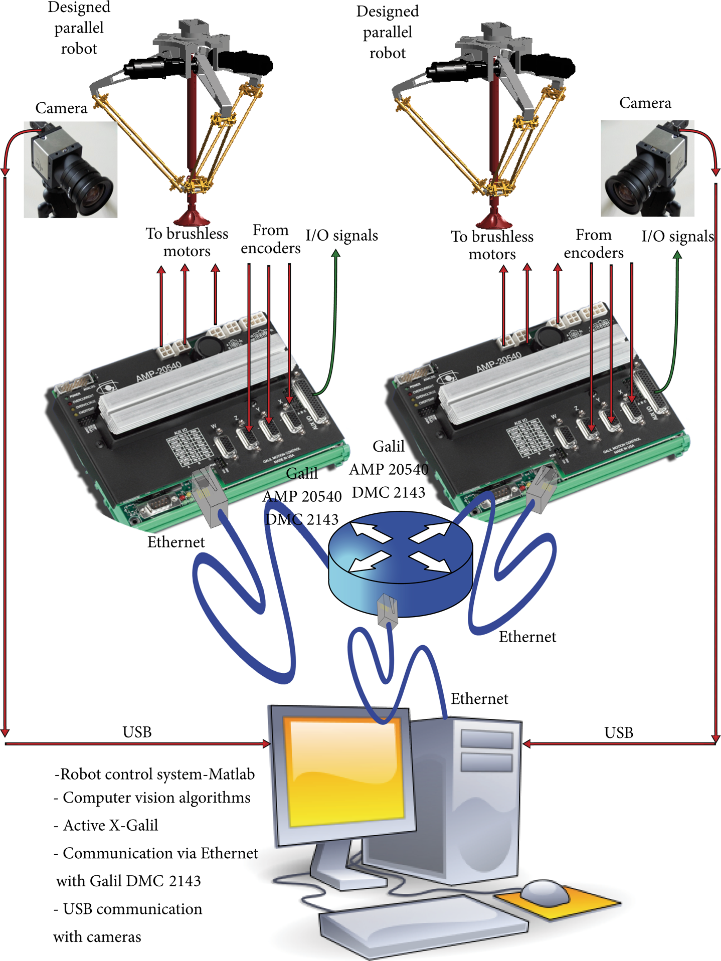
Components of the proposed robotic solution: detail.
For the control of the parallel robot, a Matlab m-function for the inverse kinematic solution was created. The user interface is currently made on Matlab Guide, which translates the desired Cartesian position to the joint variables. The activeX control from Galil is used to send the joint coordinates to the multiaxis board through Ethernet. Finally, the multiaxis board is in charge of the position loop of each motor.
Figure 13 shows a sequence of images of designed robot working in simulated environment at our laboratory. The tests performed so far allow the robot to place a work rate of 40 cycles per minute, close to 60 cycles marked as optimal. Considering that the computer vision algorithms for acquiring and processing images are implemented in Matlab and the position of the onion to be picked up is sent to the robot controller via asynchronous communication, it is expected that the designed delta robot can reach 60 cycles without problems when these delays are overcome using dedicated hardware and software.

Snapshots of the designed robot in a real experiment at our lab.
6. Conclusions
In this paper, the development of a robotic prototype for soft manipulation of vegetables has been described in detail. The whole system is composed of a parallel robotic system designed to fit with the requirements of the application; a new vacuum suction cup to produce low breaking and deformation in the manipulation and handling of this kind of vegetables; a computer vision system to compute the position and orientation of the vegetable; and a control system to command the robots based on the information provided by the computer vision software and the conveyor control system. The current prototype has shown its ability to manage, pick, and place vegetables without damaging them and with a frequency of 60 cycles per min. Our next step is to integrate the robot on the real agricultural machine and to get real data of the operation of the robot.
Conflict of Interests
The authors declare that there is no conflict of interests regarding the publication of this paper.