
Abstract
The coined-bead technique is commonly applied in the V-bending process to eliminate the spring-back feature and to achieve the required bending angle. In the present research, which is based on a stress distribution analysis, the effects of a coined-bead geometry in the V-bending process on the increased compressive stress in the bending allowance zone and on the increased reversed bending zone in the leg of the workpiece were observed and characterized. The research also illustrated the variations in spring-back and spring-go characteristics for different coined-bead widths and heights. As the bead width increased, the spring-go decreased, increased, and decreased again for different simulated bead heights and workpiece materials. The research was able to disprove previously suggested theories for coined-beaded V-bending, which suggested that a smaller bead width should be applied to cancel out the spring-back characteristic. In addition, the spring-back characteristic returned when an oversized bead width was applied. Therefore, to achieve the required bending angle, the size of the bead width was optimized both to provide a balance between a favorable stress distribution in the bending zone and reversed bending zone and to reduce the bending load.
1. Introduction
Bending is one of the basic sheet metal processes by which sheet metal is plastically deformed into curved shapes. This process can be operated using a press brake machine for small production or prototype and also using a press machine that uses press form tooling for mass production. With its economical set-up time and ability to fabricate a wide range of sizes and complex shapes of bent parts, the V-bending die is widely used for both aforementioned cases. The V-bending operation is performed by compressing sheet metal between a matching V-shaped punch and die, where its clearance is set equal to the thickness of the sheet metal. During the bending process, the metal is compressed on the punch side, and the metal is stretched on the die side. The sheet metal is plastically deformed to set a permanent bent shape. However, after unloading at the end of the deformation, elastic deformation occurs around the neutral plane of the bent part that causes the original shape to be partially recovered. In the bending process, this elastic recovery is called spring-back, which results in the obtained bending angle being larger than the required bending angle [1, 2]. In addition, the formation of the reversed bending characteristic on the leg of the workpiece results in overbending. This feature is called spring-go, which results in the obtained bending angle being smaller than the required bending angle [3–7]. Therefore, with these features, it is difficult to achieve the required bending angle. Many studies have been conducted by experiments and the finite element method (FEM) to clearly understand the bending mechanism and determine if the obtained bending angle meets the required bending angle by canceling out the spring-back/spring-go features [3–16]. Several researchers have studied the effects of the process parameters on spring-back and spring-go features, such as the punch radius [7, 8], bending angle [8, 9], material thickness [8, 9], material properties [8, 9, 11, 12], friction condition [9, 12, 13], and working temperature [13, 14], in various bending processes with different methods. In addition, many studies have also been performed to accurately predict spring-back/spring-go in various bending processes with different methods. Meinders et al. [15] developed an analytical model to predict spring-back, compensation, and optimization based on the through-thickness integration scheme for shell elements. Wang et al. [16] proposed a practical incremental bending methodology to control punch displacement using the workpiece properties estimated from measured loaded and unloaded bend angles. Ozturk et al. [14] proposed a spring-back prediction method in the wipe-bending process using a neural network. To achieve the required bending angle, the coined-bead technique, which has been known for a long time, is typically applied [1, 2]. This technique causes a bead mark on the inner surface of the bent part, and, thus, it is not suitable for bent parts where the inner surface is important. In contrast, this technique could be applied for the bent parts where the outer surface is important. However, in the past, the effects of the coined-bead geometry have hardly been investigated or clearly characterized. The coined-bead technique is generally explained that the coined-bead geometry affected the plastic deformation in the bending allowance zone by squeezing the part at the end of the bending stroke and increasing in plastic deformation [1, 2]. In the author's past research [7], the coined-bead mechanism was clearly characterized. It was revealed that the coined-bead technique could reduce the spring-back feature by the increases in the compressive stress on the bending allowance zone and the reversed bending zone on the leg of the workpiece. However, these increases in the compressive stress and the reversed bending zone depend on the coined-bead geometry and they lack research. With the lack of coined-bead database, therefore, it is sometimes difficult to achieve the required bending angle due to the difficulty in selecting the suitable coined-bead geometry related to the material property and thickness. In the present study, the effects of the coined-bead geometry on the spring-back/spring-go features were investigated using FEM and laboratory experiments. Based on a stress distribution analysis, the effects of the coined-bead geometry on spring-back and spring-go were clearly observed via the changes in the stress distribution in the bending allowance zone and in the leg of the workpiece. In addition, the effects of the coined-bead geometry on the bending force were also investigated. Experiments were performed to validate the accuracy of the FEM simulation results. Based on the bending angles and bending forces, the FEM simulation showed good agreement with the experiments in terms of both the bending angles and bending forces. Therefore, to achieve the required bending angle by applying the coined-bead technique, a suitable coined-bead geometry was sought, with particular focus on the coined-bead width, that would balance bending and reversed bending in the bent part. Specifically, with the coined-bead technique, although the spring-back feature was completely canceled out and the spring-go feature was generated in the bent part, the application of a smaller coined-bead width could not cancel out the spring-go and meet the required bending angle. In contrast, a larger coined-bead width was able to cancel out the spring-go feature and achieve the required bending angle. Therefore, to achieve a suitable coined-bead, the smallest geometry and bending force is strongly recommended.
2. FEM Simulation and Experimental Procedures
In the present study, the model of V-die bending with the coined bead was investigated, as shown in Figure 1(a), and compared with the model of V-bending without the bead, as shown in Figure 1(b). Only a half simulation model was applied to reduce the calculation time. A 30° bending angle in the V-bending model with a die radius of 6.5 mm and punch radius of 3.5 mm was investigated. The two-dimensional plane strain with a length of 60 mm and thickness of 3 mm was used as the FEM simulation model. As shown by the FEM simulation conditions listed in Table 1, the workpiece material was set as an elastoplastic type with rectangular elements, approximately 3500 elements. The punch and die were set as rigid types. The dimensions of the coined bead are also listed in Table 1. The workpiece material was aluminum A1100-O (JIS), and its properties were taken from the author's past studies [3–7]. Specifically, after doing the experiment of tensile test, an ultimate tensile strength (σ B ) of 102.5 MPa and an elongation (λ) of 43.5% were obtained. In addition, to create the material model for FEM simulation, the elastoplastic power-exponent hardening model was used, and the constitutive equation was determined from the SS (stress strain) curve, obtained by the experiment of tensile test. The strength coefficient and the strain hardening exponent values were 153.5 MPa and 0.20, respectively. In addition, SS 400 (JIS) and SAE 4340 (SAE) were also used as workpiece materials and investigated, and their mechanical properties which were obtained by doing the experiment of tensile test are listed in Table 1. The two-dimensional implicit quasi-static finite element method of a commercial analytical code, DEFORM-2D, was used for the FEM simulation. To validate the FEM simulation results, laboratory experiments were performed. As per the experiments of past studies [4–7], Figure 2 shows the press machine, which includes the 5-ton universal testing machine (Lloyd Instruments Ltd) and the V-bending die set. To control the bending stroke, the punch speed of 0.05 mm/s was set. The profile projector was used for observing and measuring the bending angle. The bending force was recorded and compared with the bending force analyzed by the FEM simulation.
FEM simulation conditions.


V-die bending models.
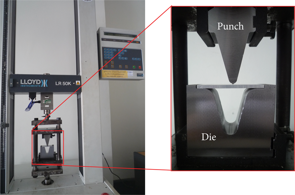
V-bending die set for experiments.
3. Results and Discussion
3.1. Stress Distribution Analysis on the Bent Part with and without a Coined Bead
Figure 3 shows the stress distribution analysis on the bent part and spring-back feature in V-bending without a coined bead. Compressive stress was generated in the sheet metal on the punch side in the bending allowance zone and on the die side in the leg of the workpiece, whereas tensile stress was generated in the sheet metal on the die side in the bending allowance zone and on the punch side in the leg of the workpiece. With this stress distribution, the spring-back feature was formed in the bending allowance zone, and the spring-go feature was formed in the leg of the workpiece. The FEM simulation results showed that the manner of the stress distribution analysis corresponded well with bending theory and literature [1–7]. After comparing these features, the formation of the spring-back feature was found to be larger than the formation of the spring-go feature, which resulted in the bent part being slightly opened out, as shown in Figure 3(b). The amount of spring-back was approximately 0.22°. With the application of the coined bead, as shown in Figure 4, the FEM simulation results showed that the compressive stress increased in the bending allowance zone, which resulted in the increase of the plastic deformation zone and a decrease in the spring-back feature. These results generally agree with the theory behind the basic bending process [1, 2]. In addition, in the leg of the workpiece, the FEM simulation results showed that the reversed bending characteristic increased, which resulted in increasing the extent of the spring-go feature. Using the FEM simulation results, the spring-go feature with a coined bead could be compared with that without the coined bead. The amount of spring-go with a coined bead was approximately −0.27°. The results confirmed that using coined bead changes the stress distribution in the bending allowance zone and the leg of the workpiece and subsequently changes the spring-back and spring-go features. These results generally agree with the theory behind the basic bending process [1, 2]. Therefore, with the application of a coined bead, the spring-back on a bent part could be canceled out by decreasing the spring-back feature in the bending allowance zone and increasing the spring-go feature in the leg of the workpiece.

Stress distribution analysis and spring-back feature without a coined bead (Al 1100-O, R p = 3.5 mm, R d = 6.5 mm, and θ = 30°). The lengths of reversed bending and bending allowance zones were measured on neutral line.

Stress distribution analysis and spring-go feature with a coined bead (Al 1100-O, R p = 3.5 mm, R d = 6.5 mm, θ = 30°, h = 0.50 mm, and w = 1.00 mm). The lengths of reversed bending and bending allowance zones were measured on neutral line.
3.2. Effects of the Coined-Bead Geometry on the Spring-Back/Spring-Go Feature
Figure 5 shows the stress distribution during the bending and coining phases with different coin-bead widths. With a bending stroke of 43.0 mm, the punch radius portion made some contact with the workpiece when the coined-bead width was smaller than 2.00 mm, as shown in Figures 5(a1), (b1), and (c1). In contrast, with a coined-bead width of 2.50 mm, the coined bead completely made contact with the workpiece without contacting the punch radius portion, as shown in Figure 5(d1). These results can be explained by the fact that, with a larger coined-bead width, bending is more difficult. Therefore, the workpiece could not be bent and contact the punch radius portion with a coined-bead width of 2.50 mm, which resulted in the bending allowance zone being smaller than that with a coined-bead width smaller than 2.00 mm.

Stress distribution analysis during bending and coining phases with different coined-bead widths (Al 1100-O, R p = 3.5 mm, R d = 6.5 mm, θ = 30°, and h = 0.50 mm). The lengths of reversed bending and bending allowance zones were measured on neutral line.
With a coined-bead width smaller than 2.00 mm, it was observed that when the larger coined-bead width was applied, the earlier the coined bead made contact with the workpiece, as shown in Figures 5(a2), (b2), and (c2). With this characteristic, the gap underneath the coined bead increased as the coined-bead width decreased because the large coined-bead width acted as a large punch tip radius. This result generally corresponds with those reported in literature [3–7]. Therefore, reversed bending was more easily generated, as shown in Figures 5(a2) and (b2), but it had not generated in the case of coined-bead width of 2.00 mm yet as shown in Figure 5(c2). In addition, it was also observed that, as the coined-bead width increased, the amount of coined material increased and the gap around the coined bead at the initial coining phase increased (zone A), as shown in Figures 5(a3), (b3), and (c3). With these features, during the coining phase, the overbending feature increased and the reversed bending characteristic in the leg of the workpiece increased because of the large coined-bead width acted as a large punch tip radius. This result also generally corresponds with those reported in the literature [3–7]. However, due to the decrease in the contact area of the punch and workpiece as the coined-bead width increased, the coined material was forced to move into the leg of the workpiece, as shown in Figure 6. It is notable that this coined material flow was opposite to that in the leg of the workpiece, which resulted in the reversed bending characteristic in the leg of the workpiece being slightly canceled out. Therefore, after compensating for the effects of over-bending and material flow features, the reversed bending characteristic in the leg of the workpiece increased and again slightly decreased as the coined-bead width increased, as shown in Figures 5(a4), (b4), and (c4). It is also notable that the bending characteristic in the bending allowance decreased due to the increase in the compressive stress as the coined-bead width increased. This result generally agrees with the theory behind the basic bending process [1, 2]. However, the application of a coined-bead width that is too small resulted in reversed bending underneath the coined-bead and could not be completely canceled out, as shown in Figure 5(a4).

Material flow analysis at the end of the coining phase with different coined-bead widths (Al 1100-O, R p = 3.5 mm, R d = 6.5 mm, θ = 30°, h = 0.50 mm, and bending stroke = 45.3 mm).
With a coined-bead width of 2.5 mm and a punch stroke of 44.8 mm, the reversed bending characteristic was generated, as shown in Figure 5(d2), and it was slightly increased as the punch stroke increase, as shown in Figure 5(d3). As mentioned earlier, the punch radius portion did not make contact with the workpiece and resulted in the coined material being easily forced to flow into the leg of the workpiece, as shown in Figure 6(d), which resulted in reversed bending in the leg of the workpiece being partially canceled out. In addition, bending occurred in the leg of the workpiece, as shown in Figure 5(d4).
As the coined-bead width increased, reversed bending in the leg of the workpiece increased and again decreased. However, the application of an undersized and oversized coined-bead width resulted in the remaining reversed bending underneath the coined bead and the formation of bending in the leg of the workpiece, respectively.
As the coined-bead height increased, the amount of coined material increased and the coining phase increased, which resulted in an increase in overbending and reversed bending in the leg of the workpiece, as the stress distribution at the end of the coining phases shows in Figure 7. In addition, the increase in the coined-bead height resulted in the increase canceling out of the reversed bending underneath the coined bead with an undersized coined-bead width, as shown in Figure 7(a). As the coined-bead height increased, reversed bending in the leg of the workpiece increased, and bending in the bending allowance zone decreased, as shown in Figures 7(b) and 7(c), which resulted in increasing the spring-go feature. It was also observed that, with an oversized coined-bead width, bending in the leg of the workpiece also increased, as shown in Figure 7(d).
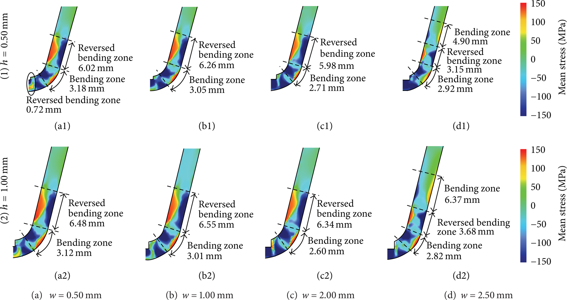
Stress distribution analysis at the end of the coining phase with different coined-bead widths and heights. (Al 1100-O, R p = 3.5 mm, R d = 6.5 mm, and θ = 30°).
The FEM simulation results revealed that the coined-bead geometry affected the stress distribution in the bending allowance zone and in the leg of the workpiece. To achieve the required bending angle, using a coined-bead geometry that balances bending and reversed bending is investigated.
3.3. The Amount of Spring-Back/Spring-Go with Different Coined-Bead Geometries
Comparing the various coined-bead geometries, the amounts of spring-back/spring-go were investigated. Figure 8 shows the amount of spring-back/spring-go with different coined-bead geometries. The results showed that the amount of spring-go decreased, increased, and again decreased as the coined-bead width increased. It is notable that the result showed the same manner for both workpiece materials (Al 1100-O and SAE 4340) with the small and large coined-bead heights. In the case of Al 1100-O with a 30° bending angle, as shown in Figure 8(a), the amount of spring-go increased for coined-bead widths in the range of 0.5–2.0 mm and again decreased with a coined-bead width greater than 2.0 mm. It was also observed that the spring-back was again generated with an oversized coined-bead width. These results confirmed that when the bead width becomes too large, the feature is unable to provide spring-go characteristics and instead causes spring-back in the final parts. These results could be clearly identified by the stress distribution mentioned earlier. With the application of an undersized coined-bead width, reversed bending remained in the bending allowance zone and resulted in the increase in the spring-go feature. As the coined-bead width increased, this remaining reversed bending was canceled out, and bending in the bending allowance zone also decreased, which resulted in a decrease in spring-back. In addition, reversed bending in the leg of the workpiece increased and again decreased, which resulted in an increase and again decrease in the spring-go feature. Spring-back on the bent part was canceled out, and spring-go was generated by applying the coined bead. Therefore, it was difficult to obtain a suitable coined-bead geometry to achieve the required bending angle. In the past, it was understood that the coined-bead geometry should be adjusted to be smaller to reduce spring-go and meet the required bending angle [1, 2]. However, in this study, it was revealed that although spring-go was generated on the bent part by applying the coined bead, the application of a smaller coined-bead geometry could not cancel out the spring-go feature to meet the required bending angle because reversed bending was generated underneath the coined bead and could not be completely canceled out by the small coined-bead width. Therefore, to achieve the required bending angle, a larger coined-bead width should be used to maintain a balance between bending and reversed bending in the bent part. However, using an oversized coined-bead width resulted in an increase in spring-back on the bent part due to the material flow and bending in the leg of the workpiece, as mentioned earlier. In the present study, spring-back was again generated when the coined-bead widths were greater than approximately 2.40 mm and 2.20 mm for coined-bead heights of 0.5 mm and 1.0 mm, respectively. Therefore, in the present study, the required bending angle of 30° could be achieved using coined-bead widths and heights of approximately 2.40 mm and 0.5 mm and 2.20 mm and 1.0 mm, respectively. Using SAE 4340 with a 45° bending angle, the same tendency between spring-back/spring-go and the coined-bead geometry was observed as that with the Al 1100-O, as shown in Figure 8(b). Specifically, as the bead width increased, spring-go decreased, increased, and again decreased for the simulated bead heights. However, it was observed that spring-back was generated in the bead width range between approximately 0.65 and 1.40 mm. In the past, with the application of a coined bead, it was understood that the coined-bead geometry should be larger to reduce spring-back and meet the required bending angle [1, 2]. However, in this research, it was revealed that the coined-bead geometry should be adjusted to be smaller to reduce spring-back and meet the required bending angle with a smaller bending load and bead mark. In this case, the required bending angle of 45° could be achieved using coined-bead widths and heights of approximately 0.60 mm and 0.50 mm, 0.55 mm and 0.75 mm, and 0.50 mm and 1.0 mm, respectively. Therefore, the size of the bead width is optimized to provide the required bending angle and reduce the bending load and bead mark. Figure 9 illustrates the optimized size of the bead widths and heights with various bending angles and workpiece materials. The results illustrated that, to achieve the required bending angle, there were many sets of coined-bead widths and heights. Therefore, the selection of suitable coined-bead geometry related to the material property, thickness, and its application was strictly considered. However, it was commonly suggested that the suitable coined-bead with the smallest geometry and bending force is strongly recommended to achieve the required bending angle.
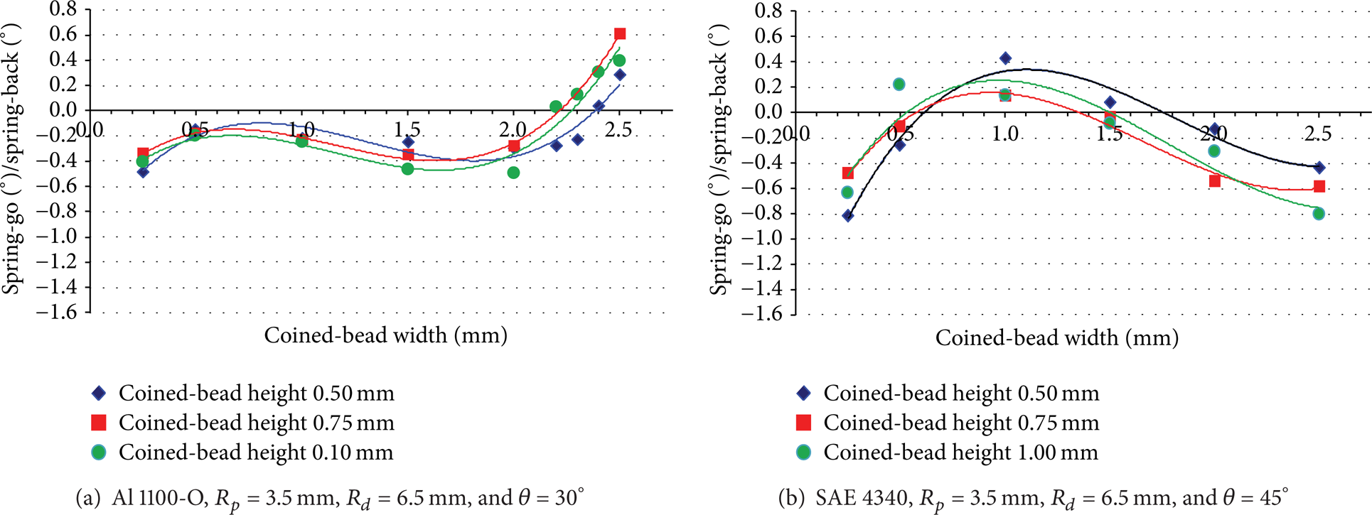
Spring-back and spring-go analyzed by FEM with different coined-bead widths and heights.

Optimized size of the bead widths and heights with various bending angles and workpiece materials (R p = 3.5 mm, R d = 6.5 mm).
3.4. Validation of FEM Simulation Results
To validate the FEM simulation results, laboratory experiments were performed. In the present study, the experiments were performed following the author's past studies [4–7]. The bending force was also considered. Using the coined bead instead of the standard punch, the bending force increased [1, 2]. The coined-bead geometry changed the bending forces, particularly in the coining phase. Figure 10 shows the bending forces with different coined-bead widths. The results showed that the bending force increased as the coined-bead width increased. It was also observed that the bending force was greatly increased in the coining phase. These results generally agree with the theory behind the basic bending process [1, 2]. In addition, the bending force analyzed by the FEM and the bending force obtained by the experiments is compared in Figure 10. The FEM simulation results showed good agreement with the experiments with an error of approximately 1%. Figures 11 and 12 compare the bending angle and bent parts obtained by the experiments and the FEM simulation, respectively, where good agreement is shown. The FEM simulation results agreed well with the experimental results in both cases of with and without a coined-bead, in which the error in the V-bending angle compared with that from the experimental results was approximately 2%. In addition, the FEM simulation also showed spring-back and spring-go formation, which agreed well with the experimental results.

Comparison of the bending force between the FEM and the experimental results (Al 1100-O, R p = 3.5 mm, R d = 6.5 mm, and θ = 30°).

Comparison of the amount of spring-back/spring-go between the FEM and experimental results (Al 1100-O, R p = 3.5 mm, R d = 6.5 mm, and θ = 30°).
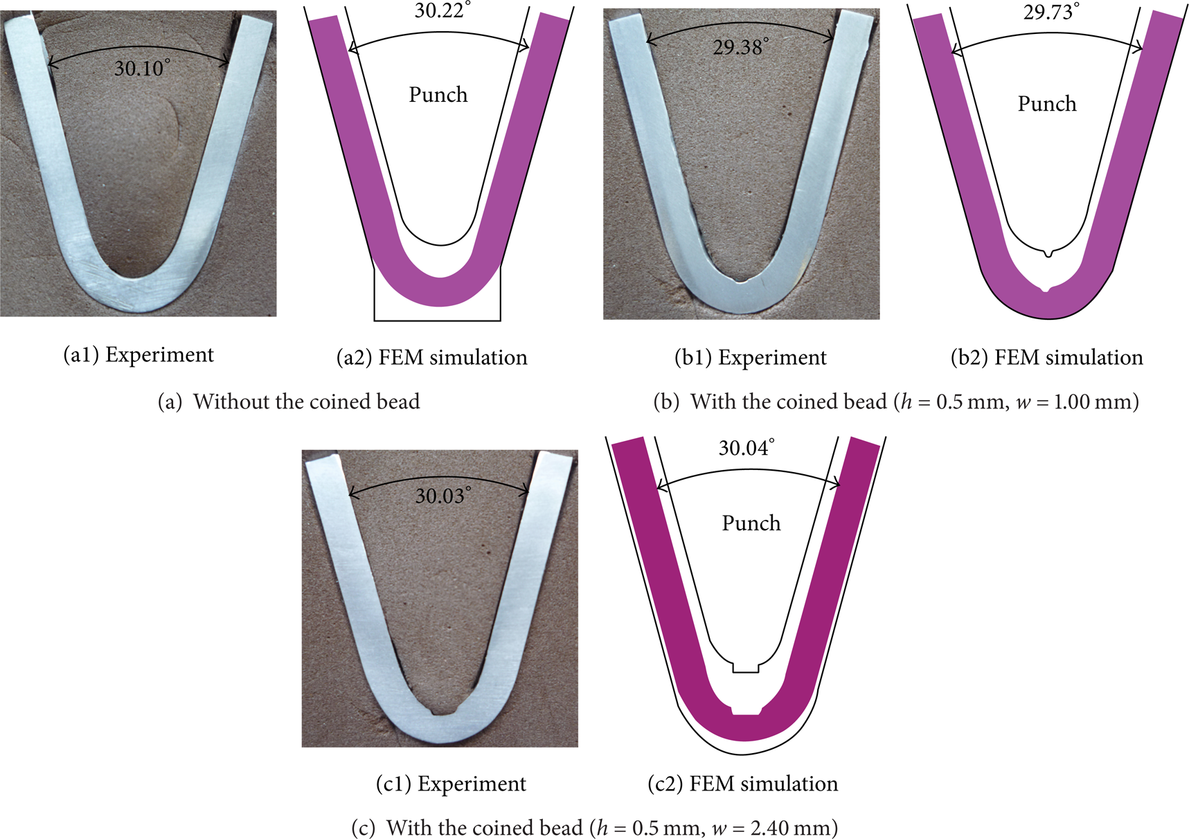
Comparison of the bent parts obtained by the experiments and the FEM simulations (Al 1100-O, R p = 3.5 mm, R d = 6.5 mm, and θ = 30°).
4. Conclusions
In the present research, the effects of coined-bead geometry on spring-back/spring-go were clearly characterized based on a stress distribution analysis. The research illustrated the variation in spring-back and spring-go characteristics for different coined-bead widths and heights. As the bead width increased, the spring-go decreased, increased, and decreased again for both the simulated bead heights and workpiece materials. In addition, the research also showed that the increases and decreases in the spring-back and spring-go characteristics depended on the bending process parameters, which included the bending angle, bead width, bead height, and workpiece material. These results disprove previously suggested theories for coined-bead V-bending, which suggested that, to cancel spring-back characteristics, a smaller bead width should be applied. In contrast, to cancel spring-go characteristics, a smaller or larger bead width can be used depending on the bending process parameters. According to the results, to achieve the required bending angle with the smallest bead size and bending load, the size of the bead should be optimized to provide a balance between the favorable stress distributions in the bending zone and reversed bending zone.
Conflict of Interests
The authors declare that there is no conflict of interests regarding the publication of this paper.
Footnotes
Acknowledgments
This work was supported by the Higher Education Research Promotion and National Research University Project of Thailand, Office of the Higher Education Commission, under Grant no. 56000519 and Grant no. 57000618.